Asko WM25 User manual

Type: WM25
Service manual
Contents
Introduction .....................................................................................................................................................................................................3
Type overview .................................................................................................................................................................................................4
Programme.......................................................................................................................................................................................................5
Indication of programme sequence........................................................................................................................................................7
Options and settings.....................................................................................................................................................................................7
Variant settings ...............................................................................................................................................................................................9
Test programme............................................................................................................................................................................................10
Fault indications............................................................................................................................................................................................12
Components and measurement values...............................................................................................................................................13
Technical data................................................................................................................................................................................................15
Circuit diagram..............................................................................................................................................................................................16
Timer diagram ..............................................................................................................................................................................................18
This service manual describes washing machine type WM25 and is a supplement to the general service
manual for the 600 series.

Service manual WM25
2
Revision history
Revision Date Description Initials
02 2008-04-28 WM25.2 can be specified with display, hence change type from
WM25.2 to WM25.3
MW
Delayed Start 1-24h implemented W723 MW
CIM motor (brushless)

Service manual WM25
3
Introduction
You are holding the service manual for the WM25 generation of washing machines.
There are three types of washing machine in the WM25 series: WM25.1, WM25.2, WM25.3. The following
page presents the different versions, to help you identify the machine types. The variants are named differ-
ently from market to market. The type designation is the most important factor for identifying the machine
type. The type designation can be found on the machine plate, which is located inside the machine’s door.
It should be easy to service a washing machine. It is important that you, as a service technician, are given
the conditions to be able to carry out work in an efficient and satisfactory way. Our hope is that this service
manual is a useful tool for your daily work.
Type designation Product number
Serial number
Week

Service manual WM25
4
WM25.3 (D/DI)
Programme: 10 (For further information, see timer diagram at the foot of the document.)
Options: 2 (designations differ depending on the market, see directions for use.)
Settings: 2 (designations differ depending on the market, see directions for use.)
Delayed start 5h delayed stary, from week 723 1-24 delayed start
CIM-motor Spin speed 400-1600 rpm
h: min
Power
W 6 3 4 2 Q U A T T R O 1 4 0 0 R P M
White
Coloured
Quick Synthetics
Wool/Hand
Rinse
Spin
DrainHeavy
Cold
30
400400 800800
40 50
60
95
Super rinse
5-hour
delayed start
High
water level
Normal
10001000
14001400
WM25.3 (C/CI)
Programme: 10 (For further information, see timer diagram at the foot of the document.)
Options: 1 (designations differ depending on the market, see directions for use.)
Settings: 2 (designations differ depending on the market, see directions for use.)
Delayed start 5h delayed stary, from week 723 1-24 delayed start
CIM-motor Spin speed 400-1600 rpm
h: min
Power
Super
rinse
W 6 2 3 2 Q U A T T R O 1 3 0 0 R P M
Cold
30
800800
13001300
40 50
60
95 White
Coloured
Quick Synthetics
Wool/Hand
Rinse
Spin
DrainHeavy
Normal
WM25.2 (B)
Programme: 10 (For further information, see timer diagram at the foot of the document.)
Options: 1 (designations differ depending on the market, see directions for use.)
Settings: None.
Display can
be specified
With display and Delayed start 1-24h
Power
W 6 1 2 2 Q U A T T R O 1 2 0 0 R P M
Super rinse
White
Coloured
Quick Synthetics
Wool/Hand
Rinse
Spin
DrainHeavy
Normal
Type overview
WM25.1 (USA)
Colors
Stain
Extra rinses
Perma press
Hand/WoolWhites
Power
W 6 0 2 2 Q U A T T R O 1 2 0 0 R P M
Programme: 4 (For further information, see timer diagram at the foot of the document.)
Options: 2 (For further information, see directions for use)
Settings: None.

Service manual WM25
5
Programme
WM25.1 (USA)
Program-
me
Pre-
wash
Main
wash
Tempe-
rature
° F
End
spin
cycle
Max rpm Max
load
Short spin
(number)
Rinses
(number)
Water con-
sumption
(approx.
litres)
Energy
consumption
(approx.
kWh)
Programme
time (ap-
prox.min)
White No Long 140 Long 1200 1/1 2 5 69 1,14 140
Colour No Short 105 Long 1200 1/1 2 5 69 0,5 75
Synthetic No Short 105 Short 800 1/2 0 3 30 0,3 65
Hand
wash/Wool
No Short 85 Short 800 1/3 0 3 54 0,3 40
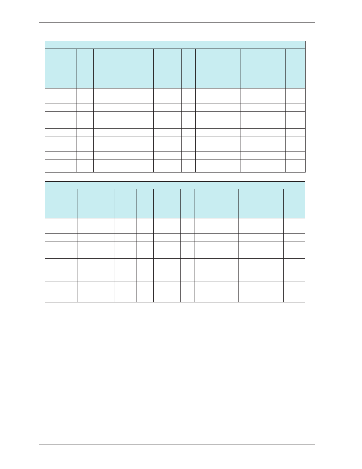
WM25.2 and WM25.3
Machine pre-programmed for 3 rinses
Programme Pre-
wash
Main
wash Temp°C Final
spin
Max
speed(rpm)
Max.
load
Short
spin
(number)
Rinses
(num-
ber)
Water
con-
sumption
(approx.
litres)
Energy
(approx.
kWh)
Pro-
gram-
me
time
(ap-
prox.
min)
Programme 1 Yes Long 95 Long 1400 1/1 3 5 80 2,1 170
Programme 2 No Long 60 Long 1400 1/1 3 3 54 1,02 130
Programme 3 No Short 60 Long 1400 1/1 3 3 50 1,1 107
Programme 4 No Short 40 Long 1400 1/1 3 3 45 0,5 70
Programme 5 No Short 40 Long 1400 1/2 0 2 25 0,4 40
Programme 6 No Short 40 Short 800 1/2 0 3 40 0,4 80
Programme 7 No Short 30 Short 800 1/3 0 3 80 0,5 45
Programme 8 No – – Long 1400 1/1 0 1 15 0,1 20
Programme 9 No – – Long 1400 1/1 0 0 0 0,1 15
Programme
10
No – – – – – 0 0 0 – 1
Machine pre-programmed for 5 rinses
Programme Pre-
wash
Main
wash Tem°C Final
spin
Max
speed(rpm)
Max.
load
Short
spin
(number)
Rinses
(num-
ber)
Water
con-
sumption
(approx.
litres)
Energy
(approx.
kWh)
Pro-
gramme
time
(approx.
min)
Programme 1 Yes Long 95 Long 1400 1/1 2 5 72 2,1 170
Programme 2 No Long 60 Long 1400 1/1 2 5 69 1,02 140
Programme 3 No Short 60 Long 1400 1/1 2 5 69 1,1 110
Programme 4 No Short 40 Long 1400 1/1 2 5 69 0,5 80
Programme 5 No Short 40 Long 1400 1/2 0 2 22 0,4 40
Programme 6 No Short 40 Short 800 1/2 0 3 30 0,4 80
Programme 7 No Short 30 Short 800 1/3 0 3 54 0,5 45
Programme 8 No – – Long 1400 1/1 0 1 9 0,1 20
Programme 9 No – – Long 1400 1/1 0 0 0 0,1 15
Programme
10
No – – – – – 0 0 0 – 1
The programme is tested in accordance with EN 60456/A11/A12/.

Service manual WM25
6
WM25.3 CIM-motor
Machine pre-programmed for 3 rinses
Programme Pre-
wash
Main
wash Temp°C Final
spin
Max
speed(rpm)
Max.
load
Short
spin
(number)
Rinses
(num-
ber)
Water
con-
sumption
(approx.
litres)
Energy
(approx.
kWh)
Pro-
gram-
me
time
(ap-
prox.
min)
Programme 1 Yes Long 95 Long 1600 1/1 3 5 80 2,1 170
Programme 2 No Long 60 Long 1600 1/1 3 3 54 1,02 135
Programme 3 No Short 60 Long 1600 1/1 3 3 55 1,1 135
Programme 4 No Short 40 Long 1600 1/1 3 3 35 0,8 75
Programme 5 No Short 40 Long 1600 1/2 0 2 35 0,4 50
Programme 6 No Short 40 Short 800 1/2 0 3 40 0,4 80
Programme 7 No Short 30 Short 800 1/3 0 3 80 0,5 45
Programme 8 No – – Long 1600 1/1 0 1 15 0,1 20
Programme 9 No – – Long 1600 1/1 0 0 0 0,1 15
Programme
10
No – – – – – 0 0 0 – 1
Machine pre-programmed for 5 rinses
Programme Pre-
wash
Main
wash Tem°C Final
spin
Max
speed(rpm)
Max.
load
Short
spin
(number)
Rinses
(num-
ber)
Water
con-
sumption
(approx.
litres)
Energy
(approx.
kWh)
Pro-
gramme
time
(approx.
min)
Programme 1 Yes Long 95 Long 1600 1/1 2 5 80 2,1 170
Programme 2 No Long 60 Long 1600 1/1 2 5 69 1,02 145
Programme 3 No Short 60 Long 1600 1/1 2 5 69 1,1 145
Programme 4 No Short 40 Long 1600 1/1 2 5 55 0,9 80
Programme 5 No Short 40 Long 1600 1/2 0 2 35 0,4 50
Programme 6 No Short 40 Short 800 1/2 0 3 40 0,4 80
Programme 7 No Short 30 Short 800 1/3 0 3 80 0,5 45
Programme 8 No – – Long 1600 1/1 0 1 15 0,1 20
Programme 9 No – – Long 1600 1/1 0 0 0 0,1 15
Programme
10
No – – – – – 0 0 0 – 1

Service manual WM25
7
Options and settings
Options
Increases the temperature and extends the time of the main wash
This option is only available on the American market.
White:
140°F / 170°F + approx 40 min
Colours: 105°F / 120°F + approximately 40 min
Permanent
press:
105°F / 120°F + approximately 15 min
Gives 2 – 4 extra rinses
This option cannot be selected with Wool/Hand wash, Rinse programme, Spin or Drain.
Machines without display
Delays the start of the machine by 5 hours
Activated by pressing the “Delayed start” button and then the start/stop button.
The number 5 in the display indicates that Time-delayed start has been activated. The num-
ber of hours to start is displayed with a countdown from 5 to 1.
Machines with display
Start machine with 5 hour delay
Activated by pressing the “Delayed Start” button and then the Start/Stop button
The number 5 is shown on the display to indicate that Delayed Start is activated.
The number of hours to start is shown in a countdown from 5 to 1.
1 - 24h delayed start successively from week 723
Start machine with 1-24 hour delay. Activated by pressing the Delayed Start option
button as many times as the desired number of hours’ delay before start (1-24 h)
and then pressing the Start/Stop button. The number of hours to delayed start is
shown on the display. The number of hours to start is shown in a countdown that
decreases 1 hour at a time.
Indication of programme sequence
During the programme, the current programme sequence is indicated by a fixed light in the LEDs around the start/stop/
door open button (see the image).
StartEnd
Final rinse Heating up
Rinsing and spinning Temperature reached

Service manual WM25
8
Produces extra water in the main wash and rinses
Cannot be selected for wool/ hand wash, spinning and draining
Settings
400400 800800
10001000
14001400
It is possible to select spin speed between 400 and 1400 rpm, CIM-motor between 400 och
1600 rpm, ”No spin”and ”No draining”(option depending on machine type).
Spin at 400 – 800 rpm means a short spin.
For certain programmes, it is not possible to select a speed in excess of 800 rpm.
“No spin”means that the programme does not include a spin cycle and ends by draining.
“No draining”means that the programme does not include a spin cycle and ends with the
water from the final rinse still in the machine.
Cold
30
40 50
60
95
Possible to select temperatures between ”Cold”and 95°C.
With ”Cold”selected, the water in the machine is not heated.
Programme number 7 does not allow a temperature above 40°C to be selected.

Service manual WM25
9
Variant settings
The variable settings below can only be made on a replacement card
Total reset
1. Hold the start/stop button (S1) in when you switch on the main power switch until an LED on the panel
lights.
Number of rinses
1. Hold both the start/stop button (S1) and door open button (S2) pressed in when you switch on the
main power switch until L7 – L16 flash.
2. Change the number of rinses by pressing the door open button (S2) repeatedly.
L1 – L3 light for three rinses. L1 – L5 light for 5 rinses.
3. Confirm your selection by pressing the start/stop button (S1).
Automatic door opening
1. Hold the door open button (S2) pressed in when you switch on the main power switch until L7 – L16
flash.
2. Change the setting by pressing the door open button (S2). L3 and L4 light when automatic door open-
ing is selected.
3. Confirm your selection by pressing the start/stop button (S1).
Super rinse or Delayed Start
1. Hold S5 or S6 pressed in when you switch on the main power switch until L7 – L16 flash.
2. Change the setting by pressing S5 or S6. All LEDs L19 – L30 light for delayed start.
3. Confirm your selection by pressing the start/stop button (S1).
Temperature/Spin speed or Stain/Super rinse
1. Hold S4 pressed in when you switch on the main power switch until L7 – L16 flash.
2. Change the setting by pressing S4. All LEDs L19 – L30 light for Stain/Super rinse.
3. Confirm your selection by pressing the start/stop button (S1).
The control unit automatically senses and adapts to the panel layout and machine model when you press
the S4 or S5 button.
L34
L1
L2
L3
L6
L4
L5
S8
S11 S6 J1
S10
S1
S2
S7
L13
L12L11
L14
L15
L16
L10
L8
L7
L9
L23
L22L21
L31
L32 L33
L24
L30
L29
L20
L25
L26
L27 L28
L19
S9 S4
S5
Main power switch
S = Push button
L = LED

Service manual WM25
10
Total reset of programmes and starting test programme
To access the test programme, total reset of the programme must be carried out as follows:
1. Make sure that the main power switch if off.
2. Hold the start/stop button (S1) in and start the machine by pressing the main power switch.
3. Check that any of the LEDs around the programme knob (L7 – L16) light. This indicates that total reset
has been carried out.
Testing LEDs
4. Press button S4/S5 and keep it depressed for approximately 20 seconds.
Note! This must be done within 3 seconds after carrying out total reset.
• All LEDs on the panel light up.
Testing inlet valves and water level (wash level)
5. Check that the door is closed.
6. Press the start/stop button (S1).
• The entire display goes out except L6 (by the start/stop
button), which starts to flash and continues to do so for
the remainder of the test programme.
•Valve 1 opens for 2 seconds.
• Valve 2 opens for 2 seconds.
• Valve 4 opens for 2 seconds.
• Valve 2 opens until level P2 (wash level) is reached.
• Valve 2 closes.
Indication of faults:
Fault indication/symp-
tom
Cause
LED L1 flashes, the
test programme stops
and ”End”is shown in
the display (applies
to machines with a
display).
Level system/valve fault
Test programme
The entire test programme is run in a sequence as follows. You can cancel the test programme at any time
during the programme by pressing the main power switch.
L34
L1
L2
L3
L6
L4
L5
S8
S11 S6 J1
S10
S1
S2
S7
L13
L12L11
L14
L15
L16
L10
L8
L7
L9
L23
L22L21
L31
L32 L33
L24
L30
L29
L20
L25
L26
L27 L28
L19
S9 S4
S5
Main power switch
S = Push button
L = LED

Service manual WM25
11
Testing element, motor, thermistor, high level, for leakage, drain pump, spinning
and door opening
7. Press the start/stop button (S1).
• The element switches on.
• The washing sequence starts.
• The water is heated to 20°C.
• The element switches off.
• The washing cycle ends.
• Valve 1 opens until level P6 (rinse level) is reached.
• Valve 2 opens for 10 seconds.
• Valve 4 opens for 10 seconds.
• The washing sequence starts.
• Leak test carried out for 20 minutes.
• The drain pump runs until level P1 (empty machine) is
reached.
•The washing cycle ends.
• Spinning at max rpm occurs for 1 minute.
• The door opens.
Indication of faults:
Fault indication/symp-
tom
Cause
LED L1 and L2 flash. Warming up fault: The
temperature rises to
20°C within one minute.
LED L2 flashes. Warming up fault
: The temperature has
not increased by 20°C
within 10 minutes.
LED L3 flashes, the
test programme stops
and ”End”is shown in
the display (applies
to machines with a
display).
Fault at water intake
(valve 1)
LED L4 and L5 flash,
the test programme
stops and ”End”is
shown in the display
(applies to machines
with a display).
Fault during leak test
(pressure drop)
LED L4 flashes, the
test programme stops
and ”End”is shown in
the display (applies
to machines with a
display).
Fault during draining
LED L5 flash. Fault during spin cycle
The test programme then stops automatically and ”End”is shown in the display (applies to machines with a
display).

Service manual WM25
12
Fault indications
The following faults are indicated by a flashing red light in the start/stop/door opening button LEDs and as
a trouble code on the display (not on all machine versions).
Fault indication Cause Action
Display L E D s ( f l a s -
hing)
Over filling. Too much
water in the machine
Service action:
1. Check the machine’s level system and inlet
valve.
Open the door Customer information:
1. Close the door and start a programme.
Service action:
1. Check the door lock.
Drainage fault Customer information:
1. Check that no objects are stuck in the drai-
nage hose outlet.
2. Check that the drain pump is not blocked by
foreign objects.
3. Check that there are no kinks in the drainage
hose.
Service action:
1. If the pump only runs for a short while (ap-
proximately 20 seconds), this indicates a
fault in the level system. Check the level
sensor and hoses.
2. Check wiring and voltage to the pump. If
necessary, replace the pump and/or control
3. After implementing corrective action, run the
Drain programme or press the Key button
(door open) to empty the machine.
Fault with water supply Customer information:
1. Check that the tap on the water pipe is open.
Service action:
1. Check that the filter in the machine’s water
intake is not blocked.
2. Check the inlet valve. If necessary, replace
the valve.
3. Check voltage to the inlet valve. If there is
no voltage, this could be due to a fault in the
level system, wiring or control unit.
Door opening fault Service action:
1. Check for faults on the door lock or wiring to
the door lock.
2. Check the function of the level sensor.
3. Check the control unit.
After carrying out corrective actions as above, reset the fault indications by switching off the machine using
the main power switch.

Service manual WM25
13
Components and measurement values
Item number Component Measurement value Comments
80 655 63
80 658 33
Motor 50 Hz
CIM-motor
Resistances:
Pins 2-3 stator 1.41 Ω
Pins 1-3 stator 0.57 Ω
Pins 4-5 rotor 1.54 Ω
(measured diagonally
across the collector)
Pins 6-7 tacho 135 Ω
Resistances:
Pins 1-3 stator 3,7 Ω
Pins 1-2 stator 3,6 Ω
Pins 2-3 rotor 3,6 Ω
Pins 4-5 tacho 178 Ω
All resistance values have tolerances
of ±8 %.
80 637 33 Motor 60 Hz Resistances:
Pins 2-3 stator 1.05 Ω
Pins 1-3 stator 0.58 Ω
Pin 4-5 rotor 1.75
Ω (Pins diagonally
across the collector)
Pins 6-7 tacho 135 Ω
All resistance values have tolerances
of ±8 %.
80 617 06 Heating Element
2000 W
28.4 Ω
80 761 02 Thermistor 6.1-3.8 k
Ω(at room tempera-
ture 20 – 30°C)
The thermistor for temperature reading
is located between the motor cradle
and the container. The thermistor mea-
sures and controls the water tempera-
ture that can vary from 0 to 90°C. The
element is disconnected if the thermis-
tor is short-circuited or disconnected
from the programme control card.
88 012 63. Drain pump 50 Hz 144 Ω. The drain pump is combined with an
integrated fine filter trap, which can be
cleaned by the user. If the drain pump
has run for 180 seconds during drain-
ing, the programme stops, resets and a
trouble code is indicated in the display
(on machines without a display, the
LEDs flash).
88 012 64. Drain pump 60 Hz 76 Ω See above.
80 782 21 Level Switch Electro mechanical level switch with
two levels, see wiring diagram. Indica-
tes levels for door opening, heat and
overfilling.

Service manual WM25
14
Item number Component Measurement value Comments
80 616 64 Pressure sensor 0.5 V out from the
sensor (at 0 bar pres-
sure and 230 V mains
voltage, measurement
carried out with the
drain pump running
to ensure 0 level is
reached)
ASKO level sensor type 1166. Controls
intake and level
80 762 02 EMC filter with induc-
tor 50/60 Hz
The filter eliminates interference to and
from the machine.
80 762 01 Inlet valve 3,7 kΩ ± 0.5 kΩ 3 way inlet valve 10 litres / minute
80 616 79 Door lock 122 Ω The door lock is electro mechanical
and equipped with a magnet.
80 771 27 Control Unit WM25.1
80 771 28 Control Unit WM25.2
80 771 29 Control Unit WM25.3
80 803 88 Control Unit WM25.3
CIM
80 822 58 Frequency motor
control

Service manual WM25
15
Technical data
Height: 850 mm
Width: 595 mm
Depth: 585 mm
Weight: 73 kg / 78 kg (with outer door)
Cylinder volume: 50 l
Max. washing capacity: 6.0 kg
Spin speed max: 800/1400 rpm
Spin speed max: CIM motor max 800/1600 rpm
Connection: 1 phase 10 A
Element power: See type plate.
Water pressure: 0,1 1 MPa., 1 10 kp/cm², 10 100 N/cm²
Wash drum and liquid compartment material: Stainless steel
Outer casing material: Powder-coated and hot-galvanized sheet steel or
stainless steel
Set-up: Stationary on four adjustable, rubber-clad feet
Water connection: 1.5 m PEX tubing, 3/4”– 3/4”or 3/4” – 1/2”
Drain: 1.7 m polypropylene tubing
Protection class: IP X4

Service manual WM25
16
Circuit diagram CIM motor

Service manual WM25
17
Circuit diagram

Service manual WM25
18
Servicemanual WM25
Drain Drain Drain Drain
Pre wash Rinse Rinse Rinse Rinse
Com
p
onents
N
F
N
N
F
SG
N
N
N
N
N
N
SG SG N/G
N
SP
N
SP
N
N
N
N
N
N
N
SP
N
N
T
F
T
F
F
D
F
T
F
T
F
F
T
T
F
H
T
WT
F
T
H
T
F
T
HHD
S
S
S
S
F
F
TD D
F
F
TD D
F
F
TD D
S
S
S
F
F
TD
Step times
Pro
g
ram
Option
Continued…
Timer diagram (description of program flow) WM25
5 rinses
3 rinses
Program 10
Super rinse
Stain (WM25A)
High water level
Program 6
Program 7
Program 8
Program 9
Program 2
Program 3
Program 4
Program 5
P5 (TO5')
12''
P5/P9 4,5'
Program 1
P3 + 30'' (TO2') ¹)
P3 30''
P3 12'' 400 rpm
P3 30''
P3 + 30'' (TO2') ¹)
P5 (TO5')
12''
P5/P9 4,5'
P3 + 30'' (TO2') ¹)
P5 (TO5')
12''
P5/P9 4,5'
P3 ca. 2' 800rpm
P5 (TO5')
12''
P5/P9 7'
P3 + 30'' (TO2') ¹)
P3 30''
P3 12'' 400 rpm
P3 30''
60''
60''
T (TO30')
4,5'
CoolDown 60''
CoolDown 60''
T (TO80')
21'
P6/P4 (TO5')
T (TO80')
2'
0'-40'
24'' (P9)
Refill 0-7 times 14'
12''
4''
Refill 0-7 times 14'
12'`
P3 + 30'' (TO2') ¹)
4''
Spin action
Motor action
Action types
28'' (P9)
Inlet valve 4, rinse-aid
Drain pump
Motor action
Heater
Inlet valve 1, pre wash/rinse
Inlet valve 2/3, mainwash
Main wash Spin Spin
Appendix: Timer diagram Page 1
Timer diagram

Service manual WM25
19
Servicemanual WM25
Drain Drain Drain Drain Drain Drain Drain Drain Drain Drain Drain
Rinse Rinse Rinse Rinse Rinse Rinse Rinse Rinse Rinse Rinse
Com
p
onents
N
N
N
N
N
G G G G
N
SP
N
SP
N
N
N
N
G G G G
N
N
G G
N
SP
N
SP SP
N
D
F
F
TD D
F
F
TD D
F
TD D
F
TD D
S
S
S
S
F
TD D
F
TD D
F
TD D
F
TD D
F
F
TD D
F
TD D
S
S
S
S
S
S
Step times
Pro
g
ram
Option
Timer diagram (description of program flow) continued
5 rinses
3 rinses
Program 10
Super rinse
Stain (WM25A)
High water level
Program 6
Program 7
Program 8
Program 9
Program 2
Program 3
Program 4
Program 5
P3 ca. 2' 800rpm
P3 ca. 8' >800rpm
30''
Program 1
P3 + 30'' (TO2') ¹)
P3 30''
P3 12'' 400 rpm
P3 30''
P5/P9 4,5'
P3 + 30'' (TO2') ¹)
P6 (TO5')
P6/P4 4,5'
P6/P4 4,5'
P3 + 30'' (TO2') ¹)
P5 (TO5')
12''
P6 (TO5')
P6/P4 4,5'
P3 + 30'' (TO2') ¹)
P6 (TO5')
P3 + 30'' (TO2') ¹)
P6 (TO5')
P6/P4 4,5'
P3 + 30'' (TO2') ¹)
P3 30''
P3 ca. 2' 800rpm
P6 (TO5')
P6/P4 4,5'
P6/P4 4,5'
P3 + 30'' (TO2') ¹)
P3 30''
P3 12'' 400 rpm
P6 (TO5')
P6/P4 7'
P3 + 30'' (TO2') ¹)
P6 (TO5')
P5 (TO5')
12''
P5/P9 4,5'
P3 + 30'' (TO2') ¹)
P5 (TO5')
12''
P5/P9 3,5'
P3 + 30'' (TO2') ¹)
P3 + 30'' (TO2') ¹)
Spin action
Motor action
Action types
Inlet valve 4, rinse-aid
Drain pump
Motor action
Heater
Spin
Inlet valve 1, pre wash/rinse
Inlet valve 2/3, mainwash
Spin
Appendix: Timer diagram Page 2
Timer diagram

Service manual WM25
20
Servicemanual WM25
Action type
Motor action
Inlet valves
Level table U-level/Volt
1,04
1,12
1,58
1,84
2,32
2,75
3,32
1,36
,,,,,,,,,,,,,,,,
–
Timer diagram, table explanation
P11-P18
P6
P7
P8
P9
P1
P3
P4
P5
2
3
4
Fill-action
SSG
G*
Valve
1
NF
N
G
SG
WT
TD
S
TO
D
T
H
HD
F
TF
¹) If P3 not has been reached within 2`, these steps will follow:
• 3`` no action
• 1` trying to reach P3
Definition
Safety: heater door opening
Drain level
Refill pre-soak and wool
Rinse level
Fill level pre-soak and wool
Reset level over-flow
Over-flow level
Identical to T-action except for the definition of the step-time. Specified step-time reduced with previos F-action or H-action
Normal wash level
Main wash (cold water)
Super gentle action: Clockwise 3 seconds on 57 seconds off, counterclockwise 3 seconds on 57 seconds off. 49rpm
Super super gentle action: Same as SG except motion, 40rpm
Pre-soak action: 1 minut off G-action, 10 minutes no motion
Refill pre-wash & main wash
Spin-action
Normal fill action: Clockwise 9 seconds on 6 seconds off, counterclockwise 9 seconds on 6 seconds off. 40rpm
Normal action: Clockwise 12 seconds on 3 seconds off, counterclockwise 12 seconds on 3 seconds off. 49rpm
Gentle action: Clockwise 3 seconds on 27 seconds off, counterclockwise 3 second on 27 seconds off. 49rpm
Main wash (hot water)
Final rinse (for rinse agent)
Time out
Definition
Pre-soak, pre-wash and rinses
Thermostop-step that heats up to selected temperature. The step will end when selected temperature is reached
Time controlled heat-step. Heats to selected temperature or to specified time elapses
The time in this step is depending of numbers of refills in the filling step
Option
Factory settings
Fill action fills up to the specified level
Fills for selected time, if selected level is not reached within the time, continue to fill to selected level is reached
Drain action, which pumps until specified level is reached + 30 seconds. If specfied level is reached within time, skip the light blue steps
Time action that executes level-control and motion as specified. Motor motion when water level exceeds. During refilling no motor motion
Appendix: Timer diagram Page 3
Timer diagram
80 800 50 Rev 02 SeRvice manual en
Other manuals for WM25
2
Table of contents
Other Asko Washer manuals

Asko
Asko PROFESSIONAL WMC743VS User manual

Asko
Asko W4086 Series User manual

Asko
Asko WM25 User manual

Asko
Asko W6124XW User manual

Asko
Asko WL6511XXLW User manual

Asko
Asko PROFESSIONAL WMC622PG User manual

Asko
Asko 20605 - User manual

Asko
Asko W6124X.W.U User manual

Asko
Asko 10505 - User manual

Asko
Asko W4086C/1 User manual
Popular Washer manuals by other brands

Frigidaire
Frigidaire FLBY06GGAWFD instruction manual

Electrolux
Electrolux WA SL3 T 201 user manual

Eskimo
Eskimo ES WM6T1200 owner's manual

Hotpoint Ariston
Hotpoint Ariston ARTXF 129 Instructions for use

AEG
AEG Lavamat 800 HC operating instructions

Bosch
Bosch WAN24252IL User manual and installation instructions