DANS01 – Installation Guide
Issue: 02 complete, approved
Page 9 of 12
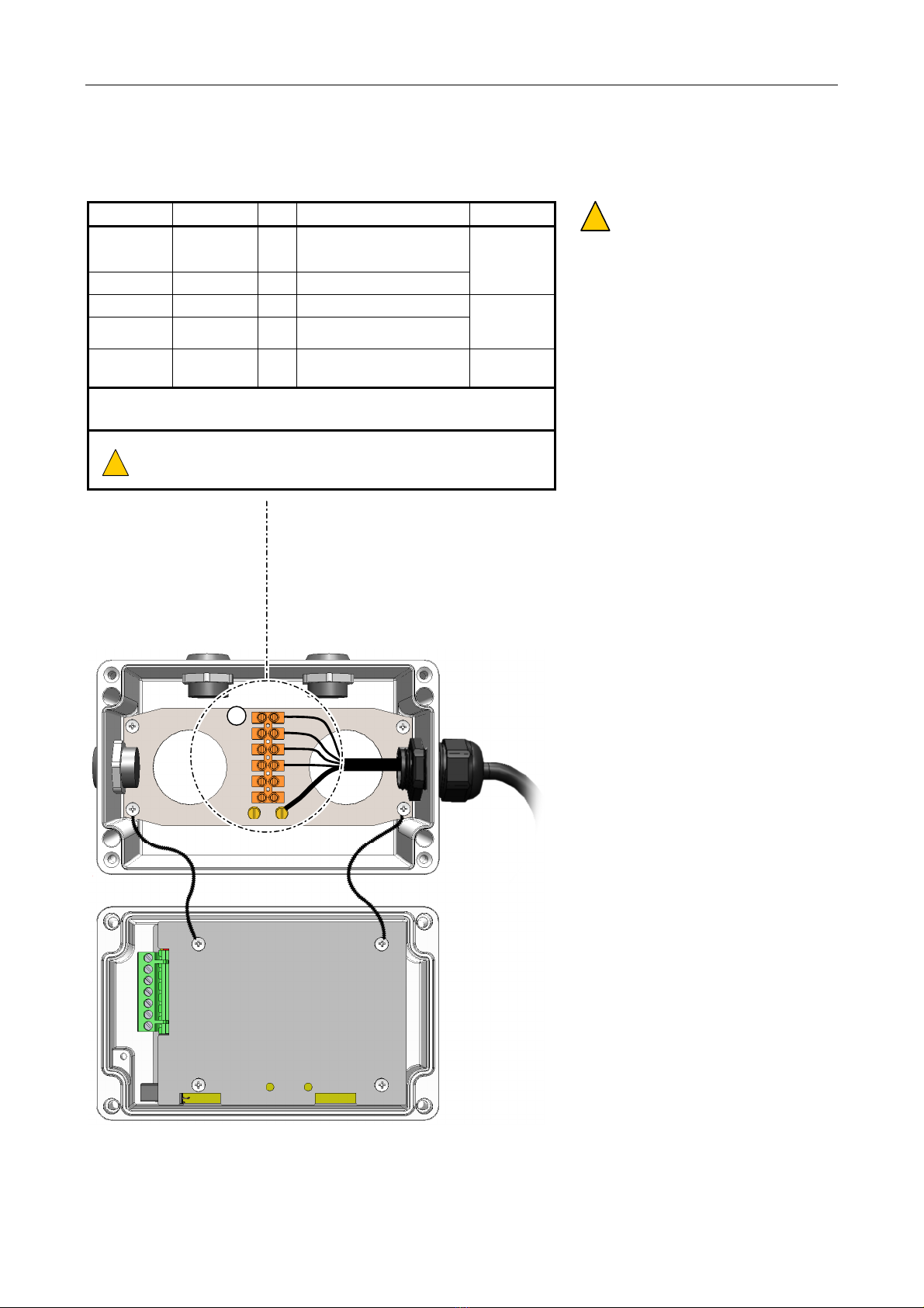
2 Connections
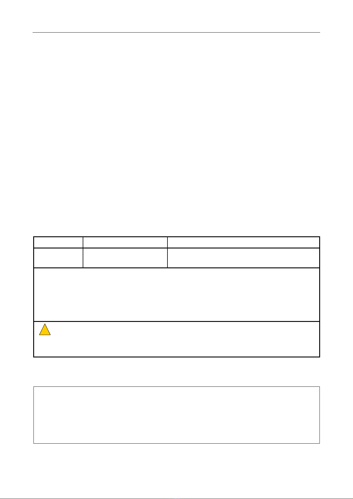
Terminal Signal I/O Description Connect
1 AUDIO+ O/P
Balanced audio output (+VE)
0 dBu (nominal) / 66 Ω
2 AUDIO- O/P As above, but -VE
To Router
3 0V Power I/P 0 V supply from system
4 +24V Power I/P +V supply (18 V – 40 V)
To power
supply from
rack
BRASS
TERMINALS - - Earth terminal Cable
screen
For cabling requirements, see Section “External Cabling
Requirements”.
!
!
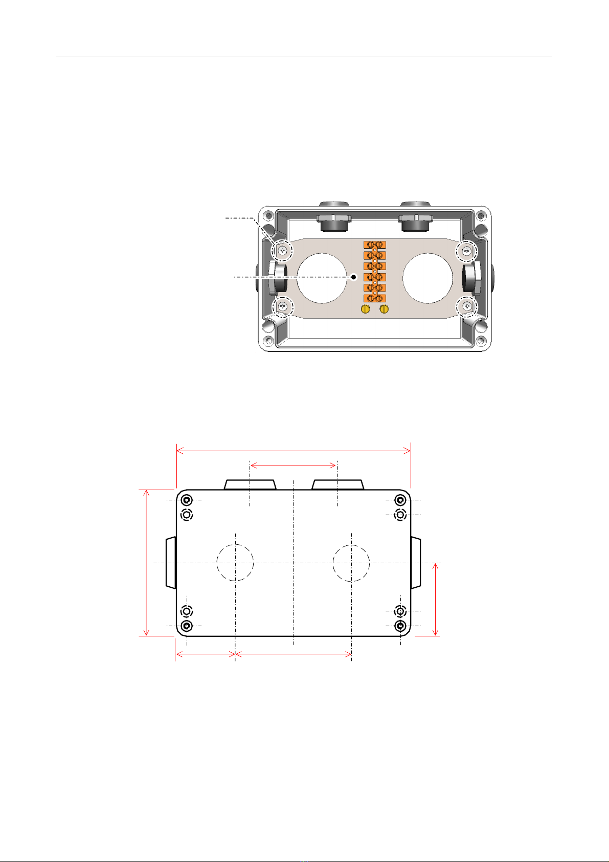
1) The cable screen should be terminated to the earth terminal
provided on the back box.
2) All screen tails must be <3 cm.
Internal wiring not shown for clarity.
Gland and cable entry point shown as example only.
FIELD WIRING
TO ROUTER
AND RACK
1
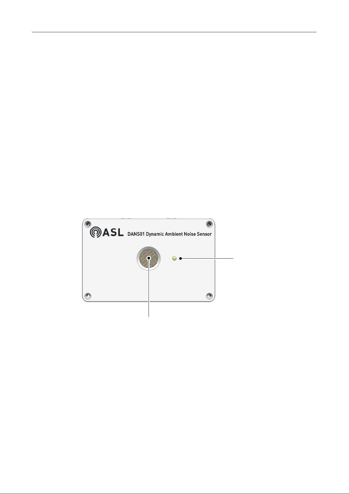
BACK BOX
FRONT PANEL
!
!
In order to deploy DANS sensors the
system should meet the followin
design requirements:
1) The DANS sensors require
VAR12 or VAR20 Routers with
MKII hardware.
Refer to ASL for details of VAR
software versions supportin
the DANS System.
2) Each DANS sensor requires one
microphone input on an Expand
Unit:
• Inputs 5 to 12 on VAR12
• Inputs 5 to 20 on VAR20
3) The DANS sensor must be
connected to a microphone
input located on the same
Expand Unit as the output(s)
that it controls.
4) Each DANS sensor also
requires an output on that
Expand Unit to be unused.
5) Up to three DANS sensors can
be connected to each Expand
Unit.
6) The Expand Units with DANS
sensor(s) do not support DVAs.
7) DANS sensors cannot be
combined with normal ANS
sensors on any zone or
roup of
zones.
8) Up to two DANS sensors can be
used to control the same
output(s).
9) DANS sensors can control more
than one output (e.
. if a zone is
separated into separate sub-
zones for other reasons).
10) Ideally if there are two DANS
sensors then they should be
connected to:
• Inputs 10 and 11 on VAR12
or VAR20, or
• Inputs 18 and 19 on VAR20