manuals.online logo
Brands
  1. Home
  2. •
  3. Brands
  4. •
  5. ASL INTERCOM
  6. •
  7. Intercom System
  8. •
  9. ASL INTERCOM BS 216 User manual

ASL INTERCOM BS 216 User manual

BS 216
DUAL CHANNEL MASTER STATION
QUICK GUIDE
October 2013
This product is designed and manufactured by:
ASL Intercom B.V.
Zonnebaan 42
3542 EG Utrecht
The Netherlands
Tel: +31 (0)30 2411901
Fax: +31 (0)30 2667373
Email: info@asl-inter.com
Web: www.asl-inter.com
PAGE 2
Quick Guide BS 216 / October 2013 © ASL Intercom BV
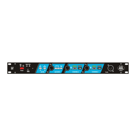
1.0 GENERAL DESCRIPTION
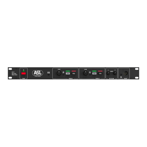
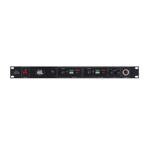
The BS 216 (19”/1RU) is designed to be a dual
channel master station in an ASL intercom
system. The unit is connected to it remote
stations by standard microphone cable
(2 conductors and 1 shield)
The built-in dual channel power supply is fully
protected against short circuit or excessive
thermal condition and can safely drive up to 15
Basic Series beltpacks operating at full power.
Each channel has a Volume (listen level) control,
a TALK and a CALL button with LED indicators.
With a headset connected to the XLR-4 headset
connector one can talk and listen to each channel
separately or to both channels simultaneously.
With side tone trimmers one may adjust the listen
level of one’s voice in one’s headset.
The unique ASL Call system provides both a
flashing red LED and a very distinctive sound
signal. A slight touch of the CALL button makes
the call LED flash, whilst holding the button for 2
seconds the call sound signal is activated.
An Aux input at the rear panel allows injecting
external audio signals of line or mic level into the
intercom lines. If ‘mic level’ is selected, +30V DC
phantom power is available at the Aux input
connector.
Special attention has been paid to the intelligibility
of speech. By applying low noise/high speed
circuitry, a speech presence filter and a specially
designed headphone amplifier, communication is
very comfortable even in environments with high
background noise levels.
2.0 UNPACKING
The shipping carton contains the parts listed below
* The BS 216
* Mains power cable
* Spare fuses
If any are missing, contact your dealer.
ASL has taken great care to ensure that this
product reaches you in flawless condition.
After unpacking the unit please inspect for any
physical damage to the unit, and retain the
shipping carton and relevant packing materials for
use should the unit need returning. If any damage
has occurred, please notify your dealer
immediately so that a written claim can be
initiated. Please also refer to the warranty section
of this quick guide.
3.0 MAINS POWER & SAFETY EARTH
Connecting to mains power :
The BS 216 may be connected to a mains power
outlet which provides 100 – 240 V AC, 50-60 Hz
and at least 60 watts. The outlet should have a
clean earth. Avoid using mains power outlets which
also power dimmer controlled lighting equipment.
The wires in the mains lead are color coded:
green/yellow: Earth / Safety Ground
blue: Neutral / brown: Live
In case the wires in the mains lead do not
correspond with the colored markings identifying the
terminals in your mains plug, proceed as follows:
•The wire which is colored green/yellow must
be connected to the terminal in the plug
which is marked with the letter “E”, or by the
ground symbol, or is colored green.
•The wire which is colored blue must be
connected to the terminal which is marked
with the letter “N” or is colored black.
•The wire which is colored brown must be
connected to the terminal which is marked
with the letter “L” or is colored red.
Safety Earth :
For personal safety and proper functioning of
the BS 216 and its connected stations, the
green/yellow wire of the mains lead must
always be connected to the electrical
installation safety earth or ground.
The green/yellow wire is in the BS 216 connected
to all exposed metal surfaces.
Any rack framework into which this unit might be
mounted is assumed to be connected to the
same grounding circuit.
PAGE 3
Quick Guide 216 / Issue October 2013 © ASL Intercom BV
4.0 WARRANTY
This unit is warranted by ASL the original end-user
purchaser against defects in workmanship and
materials in its manufacture for a period of one year
from date of shipment to the end-user. Faults
arising from misuse, unauthorized modifications or
accidents are not covered by this warranty.
If the unit is faulty it should be sent in its original
packing, to the supplier or your local ASL dealer,
with shipping prepaid. A note must be included
stating the faults found and a copy of the original
suppliers invoice.
5.0 MECHANICAL INSTALLATION
For the BS 216 a vertical rack space of 1U (1.75”,
44mm) is required. It is not necessary to provide
rear support by extra bracing or shelving.
Adequate ventilation must be provided by
allowing sufficient space around the sides and
rear of the unit to ensure free circulation of air.
Forced cooling is not required.
The power supply regulator is mounted on the
rear of the unit; after a period of time it will feel
hot to the touch. This is quite normal, and should
be no cause for alarm.
6.0 FRONT PANEL CONTROLS & CONNECTOR
1 POWER ON/OFF switch
To switch mains power on or off.
2 MAINS POWER LED
This LED illuminates if line power is supplied by
the internal power supply.
3 BUZZER VOLUME trimmer
To adjust the volume of the buzzer.
The internal buzzer indicates an incoming or
outgoing call. It is activated by pushing a CALL
button on this station or a CALL button on any
other station for longer than two seconds.
4 VOLUME A & B control knobs
To adjust the listen level of the headset
5 SIDE TONE trimmers
To adjust the level of one’s voice as heard in
one’s headset. Adjustment procedure (for each
channel separately):
•set the trimmer in start position: fully
clockwise
•switch off the microphones of all
connected stations
•push the TALK button of the channel
•turn up the volume of the channel
•speak into the headset microphone
•adjust the listen level by turning the side
tone trimmer of the channel.
The trimmer operating area is between fully
clockwise and minimum level. Adjusting the side
tone does not affect the level of your voice as
heard by other stations.
6 TALK A & B buttons + LED’s
To allow the user to talk to each channel
separately or to both channels simultaneously.
The large green LED’s indicate if the talk button
is switched On.
7 CALL A & B buttons + LED’s
To activate the Call system.
By a momentary push a Call signal is sent to all
stations connected to the referring intercom
channel. The Call LED on this station and on all
to the channel connected stations starts flashing.
Pushing and holding a Call button for 2 seconds
activates the call buzzer in all stations. After the
CALL button is released the Call LED’s continue
to flash for a further 2 seconds.
8 AUX VOLUME controls A & B
To adjust the level of the Aux input signal to each
of the two intercom lines.
9 HEADSET connector (XLR-4)
To connect a headset to the BS 216. The headset
can impedance must be minimum 200 ohms.
The headset microphone may be of the dynamic
or electret type.
For pin assignment, see the BS 216 user manual.
PAGE 4
Quick Guide 216 / Issue October 2013 © ASL Intercom BV
7.0 REAR PANEL CONTROLS & CONNECTORS
10 MAINS Inlet
IEC Mains connector
11 FUSE Holder
The fuse protects the BS 216 against severe
internal damage, in case of malfunction in the
power section.
12 AUX INPUT connector
This aux signal input is electronically balanced
and accepts mic or line level audio signals.
Pin assignment :
Pin 1. 0V / ground
Pin 2: signal +
Pin 3: signal –
13 INPUT LEVEL Switch
To select mic or line level audio. If mic level is
selected, +30 V DC phantom power is supplied to
pin 2 and 3 of the aux input connector
14 MIC GAIN Trimmer
To adjust the input gain when mic level is
selected (see #13)
15 A & B LINE connectors (XLR-3)
To connect remote stations to the BS 216, using
standard microphone cable. Pin assignment:
Pin 1: 0V / ground shield
Pin 2: +30V DC power wire
Pin 3: audio wire
8.0 INTERNAL CONTROLS
MIC GAIN. The headset mic gain is adjusted by a trimmer located on the PCB near the headset connectors
.
9.0 TECHNICAL SPECIFICATIONS
Intercom system
Dynamic range: 80 dB (1kHz, THD <1%)
Frequency response: 200 Hz - 15 kHz (-3 dB)
Call signal (send): +2.8 mA
Call signal threshold (receive): +2.4 V DC
Operating voltage: 24 - 32 V DC
Line impedance: 350 Ω (1 kHz), 2.2 kΩ (DC)
Audio level: nom. -18 dBu, max. 0 dBu
Switch Mode Power Supply
Mains voltage: 100 - 240 V AC, 50/60 Hz
Output voltage: +30 V DC (+/- 5%)
Max output power: 45 W
Mic Pre-amp
Gain: 40 - 60 dB (adjustable internally)
Presence filter: +6dB @ 5 kHz
Power to electret mic: +9 V DC
Headphone Driver Amp
Max. output level: 11.6 Vrms (at 200 Ω)
Max. output power: 0.7 Wrms (at 200 Ω)
Side Tone Rejection: 0 - 30 dB adjustable
Buzzer Max. SPL: 85 dBA
Aux Input
Input Impedance:
30 kΩ(line level)
4.6 kΩ(mic level)
Nominal Input Level:
0 dBu (line level)
-30 dBu (mic level)
Max. Input Level:
+22 dBu (line level)
0 dBu (mic level)
Phantom Power: +30 V DC (mic level selected)
0 dBu is defined as 775 mV rms into open circuit.
ASL reserves the right to alter specifications without prior notice
For safety instructions, block diagram, system configuration and party line concept & cabling, see
the BS 216 User Manual. Go to www.asl-inter.com, section ‘Support’

Other manuals for BS 216

2

Other ASL INTERCOM Intercom System manuals

ASL INTERCOM PS 278 User manual

ASL INTERCOM

ASL INTERCOM PS 278 User manual

ASL INTERCOM PS 279 User manual

ASL INTERCOM

ASL INTERCOM PS 279 User manual

ASL INTERCOM BS 17 User manual

ASL INTERCOM

ASL INTERCOM BS 17 User manual

ASL INTERCOM PS 19 AM User manual

ASL INTERCOM

ASL INTERCOM PS 19 AM User manual

ASL INTERCOM BS 15 User manual

ASL INTERCOM

ASL INTERCOM BS 15 User manual

ASL INTERCOM PS 130 User manual

ASL INTERCOM

ASL INTERCOM PS 130 User manual

ASL INTERCOM BS 216 User manual

ASL INTERCOM

ASL INTERCOM BS 216 User manual

ASL INTERCOM BS 217 User manual

ASL INTERCOM

ASL INTERCOM BS 217 User manual

ASL INTERCOM PRO Series User manual

ASL INTERCOM

ASL INTERCOM PRO Series User manual

ASL INTERCOM PS 4379 User manual

ASL INTERCOM

ASL INTERCOM PS 4379 User manual

ASL INTERCOM PS 19 A User manual

ASL INTERCOM

ASL INTERCOM PS 19 A User manual

ASL INTERCOM SMC02G User manual

ASL INTERCOM

ASL INTERCOM SMC02G User manual

ASL INTERCOM BS 217 User manual

ASL INTERCOM

ASL INTERCOM BS 217 User manual

ASL INTERCOM IS 141 User manual

ASL INTERCOM

ASL INTERCOM IS 141 User manual

ASL INTERCOM PS 6379 User manual

ASL INTERCOM

ASL INTERCOM PS 6379 User manual

ASL INTERCOM PS 6379 Mk2 User manual

ASL INTERCOM

ASL INTERCOM PS 6379 Mk2 User manual

ASL INTERCOM WS-400 User manual

ASL INTERCOM

ASL INTERCOM WS-400 User manual

ASL INTERCOM BS 216 User manual

ASL INTERCOM

ASL INTERCOM BS 216 User manual

ASL INTERCOM TS 99 User manual

ASL INTERCOM

ASL INTERCOM TS 99 User manual

ASL INTERCOM PS 6379 Mk2 User manual

ASL INTERCOM

ASL INTERCOM PS 6379 Mk2 User manual

ASL INTERCOM BS 17 User manual

ASL INTERCOM

ASL INTERCOM BS 17 User manual

ASL INTERCOM PS 630 User manual

ASL INTERCOM

ASL INTERCOM PS 630 User manual

ASL INTERCOM PS 155 User manual

ASL INTERCOM

ASL INTERCOM PS 155 User manual

Popular Intercom System manuals by other brands

Orno OR-DOM-CL-909 user manual

Orno

Orno OR-DOM-CL-909 user manual

CAME BPT MTMA/IP Programming manual

CAME BPT

CAME BPT MTMA/IP Programming manual

Mircom EP-1000 installation manual

Mircom

Mircom EP-1000 installation manual

Somogyi home DB 118 instruction manual

Somogyi

Somogyi home DB 118 instruction manual

ViziT BVD-406 Series manual

ViziT

ViziT BVD-406 Series manual

BERNSTEIN VDM-10-MT user manual

BERNSTEIN

BERNSTEIN VDM-10-MT user manual

SCS XOE8 SUB Installation and user manual

SCS

SCS XOE8 SUB Installation and user manual

Bticino 322011 manual

Bticino

Bticino 322011 manual

Farfisa Mycom 1MCFCPL manual

Farfisa

Farfisa Mycom 1MCFCPL manual

Aiphone MK Series Installation & operation manual

Aiphone

Aiphone MK Series Installation & operation manual

ESP Aperta APDSPXMW user manual

ESP

ESP Aperta APDSPXMW user manual

urmet domus 1062/100 manual

urmet domus

urmet domus 1062/100 manual

Vingtor Stentofon TCIS-1 Mounting manual

Vingtor Stentofon

Vingtor Stentofon TCIS-1 Mounting manual

Vokkero SQUADRA 8 user guide

Vokkero

Vokkero SQUADRA 8 user guide

ALERTUS SIP Annunciator installation guide

ALERTUS

ALERTUS SIP Annunciator installation guide

quhwa VP-700A instruction manual

quhwa

quhwa VP-700A instruction manual

urmet domus 6025/401 quick start guide

urmet domus

urmet domus 6025/401 quick start guide

FARFISA INTERCOMS Kit 2PEXD installation instructions

FARFISA INTERCOMS

FARFISA INTERCOMS Kit 2PEXD installation instructions

manuals.online logo
manuals.online logoBrands
  • About & Mission
  • Contact us
  • Privacy Policy
  • Terms and Conditions

Copyright 2025 Manuals.Online. All Rights Reserved.