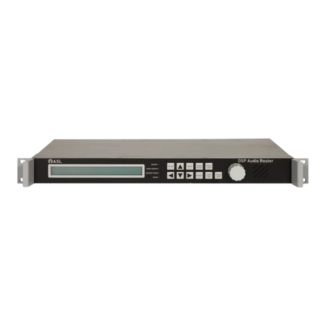
ASL INTERCOM VAR4 User manual

VAR4 / VAR12 / VAR20
DSP Audio Router
ASL Document Ref.: U-0450-1405.doc
Issue: 04 - complete, approved - Date: 19/08/10
Operation Manual

VAR4 / VAR12 / VAR20 - Operation Manual
sue: 03 complete, approved
Copyright © 2007 Application Solutions Limited
Application Solutions Limited
Safety, Security and Control Division
Unit 17 Cliffe Industrial Estate
Lewes - East Sussex
BN8 6JL - UK
Tel: +44(0)1273 405411 Fax: +44(0)1273 405415
www.asl-electronics.co.uk
All rights reserved.
Information contained in this document is believed to be accurate, however no representation or warranty is given and
Application Solutions Limited assumes no liability with respect to the accuracy of such information.
Is
Page 2 of 308
This equipment is designed and manufactured to conform to the following EC standards:
EMC EN55103-1/E1, EN55103-2/E5, EN50121-4, ENV50204
Safety EN60065
Failure to use the equipment in the manner described in the product literature will
invalidate the warranty.
A ‘Declaration of Conformity’ statement to the above standards, and a list of auxiliary
equipment used for compliance verification, is available on request.
This product must be disposed of in accordance with the WEEE directive.

VAR4 / VAR12 / VAR20 - Operation Manual
Is
Page 3 of 308
sue: 03 complete, approved
Contents
1Introduction .............................................................................................................................................. 9
1.1 About this Document .................................................................................................................. 9
1.2 VAR Router SW Version ............................................................................................................ 9
2VAR Router Operation........................................................................................................................... 10
2.1 VAR Router Front Panel........................................................................................................... 10
2.1.1 Indicators .......................................................................................................................... 10
2.1.2 Controls............................................................................................................................. 11
2.1.2.1 Access Code ............................................................................................................. 12
2.1.2.2 LCD Display Timeouts .............................................................................................. 12
2.1.2.3 Restoration of Default Settings ................................................................................. 12
2.2 Responding to Fault Indications ............................................................................................... 13
2.2.1 Records............................................................................................................................. 13
2.2.2 Action Following a Fault.................................................................................................... 13
2.3 Navigating the Menus............................................................................................................... 14
2.3.1 Display Structure...............................................................................................................14
2.3.2 Menu Selection Markers ................................................................................................... 14
2.3.3 Selecting Menu Item and Saving Changes ...................................................................... 14
2.3.4 Changing an Option.......................................................................................................... 15
2.3.5 Rotary Encoder ................................................................................................................. 15
2.4 Conventions Used in this Manual............................................................................................. 15
2.5 Menu Map of Functions ............................................................................................................ 16
3Typical Configuration Process............................................................................................................. 18
4Accessing the VAR Router ................................................................................................................... 20
4.1 Initialisation............................................................................................................................... 20
4.2 Logging On ............................................................................................................................... 21
4.3 Logging Off ............................................................................................................................... 21
4.4 Changing the System Access Code......................................................................................... 22
5VAR Router Configuration .................................................................................................................... 23
5.1 VAR Router Operation Mode.................................................................................................... 23
5.1.1 Network Topology............................................................................................................. 23
5.1.1.1 System Parameters................................................................................................... 23
5.1.1.2 Main Network Features ............................................................................................. 23
5.1.2 Setting the VAR Router to Stand-alone Operation ........................................................... 25
5.1.2.1 Network Channel Configuration ................................................................................ 25
5.1.2.2 Mic/Line Inputs 1, 3 and 4 Type Configuration ......................................................... 26
5.1.3 Setting the VAR Router to Network Operation ................................................................. 27
5.1.3.1 Network Channel Configuration ................................................................................ 27
5.1.3.2 Mic/Line Input Configuration as Network Channel.................................................... 28
5.1.3.3 Network Channel Surveillance Tone Detection ........................................................ 29
5.1.3.4 Network Channel Equalisation Configuration ........................................................... 30
5.1.3.5 Network Channel Fade Up and Down Time Configuration....................................... 31
5.1.3.6 Network Channel Pre-announcement Chime Configuration..................................... 32
5.1.3.7 Network Channel Input Gain and the Line Sensitivity Configuration ........................ 33
5.1.3.8 Network Channel Relative Gain Configuration ......................................................... 34
5.1.3.9 Network Channel Name Configuration ..................................................................... 35
5.1.3.10 Network Input Ambient Noise Sensor (ANS) Configuration...................................... 37
5.1.3.11 Network Input Fallback.............................................................................................. 39
5.1.3.12 Network Priority Configuration .................................................................................. 40
5.1.3.13 Audio Control Unit Configuration .............................................................................. 40
5.2 VAR ID...................................................................................................................................... 41
5.3 VAR Router Name.................................................................................................................... 41
5.4 System Date / Time .................................................................................................................. 42
5.5 Temperature ............................................................................................................................. 43
5.6 RS-232 Asynchronous Port ...................................................................................................... 43
5.7 Emergency Sounder Operation................................................................................................ 44

VAR4 / VAR12 / VAR20 - Operation Manual
Is
Page 4 of 308
sue: 03 complete, approved
5.8 Remote Fault Output Configuration.......................................................................................... 44
5.9 Host Protocol Configuration...................................................................................................... 46
5.9.1 Routing Timeout Configuration ......................................................................................... 46
5.9.2 Fault Timeout Configuration ............................................................................................. 47
5.9.3 Make Route Message Format Configuration.................................................................... 47
5.9.4 Password Control Configuration ....................................................................................... 48
5.10 Configuration Data.................................................................................................................... 50
5.10.1 Configuration Data View ................................................................................................... 50
5.10.2 Clearing Configuration Data and Restoring to Default Settings ....................................... 50
5.11 VAR Router Software Versions ................................................................................................ 51
6ASL Amplifier Mainframe Commissioning .......................................................................................... 52
6.1 Detecting Frames Using ‘Learn’ Mode ..................................................................................... 52
6.2 Viewing Configured Mainframes .............................................................................................. 54
6.2.1 Verbose View....................................................................................................................54
6.2.2 Terse View ........................................................................................................................ 55
6.3 Mainframe Commissioning ....................................................................................................... 56
6.3.1 Viewing a Mainframe Configuration.................................................................................. 56
6.3.2 Editing/Viewing a Mainframe Description ......................................................................... 57
6.3.3 Configuring a Mainframe Temperature Alarm .................................................................. 58
6.3.4 Commissioning an Amplifier Slot ...................................................................................... 59
6.3.4.1 Editing/Viewing an Amplifier Slot Description ........................................................... 59
6.3.4.2 Configuring an Amplifier’s Internal Audio Path AC Surveillance............................... 60
6.3.4.2.1 Configuring an Amplifier’s AC Surveillance Tone Frequency Range................ 60
6.3.4.2.2 Configuring an Amplifier’s AC Surveillance Thresholds.................................... 62
6.3.4.2.3 Configuring an Amplifier’s AC Surveillance Interval.......................................... 64
6.3.4.3 Configuring an Loudspeaker Line DC Surveillance .................................................. 65
6.3.4.4 Configuring an Loudspeaker Line Earth Leakage Monitoring................................... 67
6.3.5 Mainframe Learn Check ................................................................................................... 68
7Mic/Line Input Configuration ................................................................................................................ 70
7.1 Mic/Line Input Type Configuration............................................................................................ 73
7.2 Parameters Common to All Mic/Line Input Types .................................................................... 75
7.2.1 Input Surveillance Tone Detection Configuration ............................................................. 75
7.2.2 Input Equalisation Configuration....................................................................................... 77
7.2.3 Input Fade Up and Down Time Configuration .................................................................. 79
7.2.4 Input Pre-announcement Chime Configuration ................................................................ 82
7.2.5 Input Gain and the Line Sensitivity Configuration............................................................. 84
7.2.6 Input Relative Gain Configuration..................................................................................... 86
7.2.7 Input Priority Configuration ............................................................................................... 88
7.2.8 Input Phantom Power Configuration................................................................................. 90
7.2.9 Input Emergency Class..................................................................................................... 91
7.2.10 Input Name Configuration................................................................................................. 93
7.2.11 Input Ambient Noise Sensor (ANS) Configuration............................................................ 94
7.2.12 Local Fallback Configuration ............................................................................................ 96
7.3 Paging Microphone and Zoned Fire Microphone Specifics...................................................... 98
7.3.1 PTT Button Configuration ................................................................................................. 98
7.3.2 PTT Button Cough Timeout Configuration ..................................................................... 100
7.3.3 Listen-in Configuration.................................................................................................... 102
7.3.4 Microphone Button Configuration ................................................................................... 105
7.3.4.1 Configuring a Button as Unused ............................................................................. 106
7.3.4.2 Configuring a Button for Microphone Routing (Zone Selection) ............................. 109
7.3.4.3 Configuring a Button for DVA Routing/Other Input Routing.................................... 112
7.3.4.3.1 Configuring the Route for a DVA Routing Button............................................ 115
7.3.4.3.2 Configuring a DVA Routing Button for Non-latching Mode ............................. 118
7.3.4.3.3 Configuring a DVA Routing Button for Latching Mode.................................... 120
7.3.4.3.4 Configuring a DVA Routing Button for Play Once Mode................................. 123
7.3.4.3.5 DVA Routing Button Busy Indication Configuration ........................................ 125
7.3.4.3.6 DVA Routing Button DVA Play Mode Configuration ....................................... 127
7.3.4.3.7 Clearing the Route Associated with a DVA Routing Button............................ 129
7.3.4.4 Configuring a Button as an All-Call Button.............................................................. 130

VAR4 / VAR12 / VAR20 - Operation Manual
Is
Page 5 of 308
sue: 03 complete, approved
7.3.4.5 Security Key-switch Configuration .......................................................................... 133
7.4 Single Button Microphone Specific Configuration .................................................................. 135
7.4.1 PTT Button Zone Selection Configuration ...................................................................... 135
7.4.2 PTT Button Cough Timeout Configuration ..................................................................... 137
8DVA Input Configuration ..................................................................................................................... 139
8.1 DVA Input Gain Configuration ................................................................................................ 139
8.2 DVA Input Relative Gain Configuration .................................................................................. 140
8.3 DVA Input Priority Configuration............................................................................................. 141
8.4 DVA Input Emergency Class .................................................................................................. 143
8.5 DVA Input Name Configuration .............................................................................................. 145
8.6 DVA Input Ambient Noise Sensor (ANS) Configuration......................................................... 146
9Background Music Configuration ...................................................................................................... 148
9.1 Music Input Configuration....................................................................................................... 149
9.1.1 Music Input Equalisation Configuration .......................................................................... 149
9.1.2 Music Input Fade Up and Down Time Configuration...................................................... 150
9.1.3 Music Input Gain Configuration ...................................................................................... 152
9.1.4 Music Input Relative Gain Configuration ........................................................................ 153
9.1.5 Music Input Priority Configuration................................................................................... 154
9.1.6 Music Input Emergency Class ........................................................................................ 155
9.1.7 Music Input Name Configuration .................................................................................... 155
9.1.8 Music Input Ambient Noise Sensor (ANS) Configuration ............................................... 156
9.2 Contact Music Selector Configuration .................................................................................... 158
10 Mute Input Configuration .................................................................................................................... 160
10.1 Mute Input Emergency Class ................................................................................................. 160
10.2 Mute Input Priority Set-up....................................................................................................... 161
11 Test Tone Input Configuration............................................................................................................ 163
11.1 Test Tone Type Configuration................................................................................................ 164
11.2 Test Tone Input Gain Configuration ....................................................................................... 164
11.3 Test Tone Input Priority Set-up............................................................................................... 165
12 Output Configuration........................................................................................................................... 167
12.1 Gain Configuration.................................................................................................................. 167
12.2 Equalisation Configuration...................................................................................................... 168
12.3 Ambient Noise Sensor (ANS) Configuration .......................................................................... 170
12.3.1 Enabling/Disabling the ANS and Setting the Attack Time .............................................. 172
12.3.2 Configuring the ANS Range ........................................................................................... 173
12.4 Surveillance Tone Generation Configuration ......................................................................... 175
12.5 Override Gain Configuration................................................................................................... 177
12.6 Name Configuration................................................................................................................ 178
13 Induction Loop Configuration ............................................................................................................ 180
13.1 Setting the VAR Router to Support Induction Loop................................................................ 182
13.2 Induction Loop Output Gain Configuration ............................................................................. 183
13.3 Induction Loop Output Surveillance Tone Generation Configuration..................................... 184
13.4 Induction Loop Output Override Gain Configuration .............................................................. 186
13.5 Induction Loop Output Name Configuration ........................................................................... 187
13.6 Induction Loop Parameter Configuration................................................................................ 188
13.6.1 Configuring the Induction Loop Type.............................................................................. 188
13.6.2 Equalisation Configuration.............................................................................................. 189
13.6.3 Audio Compression Configuration .................................................................................. 190
14 Contact Configuration ......................................................................................................................... 193
14.1 Configuring a Contact as Unused .......................................................................................... 194
14.2 Configuring a Contact for Routing .......................................................................................... 196
14.2.1 Configuring the Zone Selection for a Routing Contact ................................................... 199
14.2.2 Configuring a Routing Contact for Non-latching Mode ................................................... 201
14.2.3 Configuring a Routing Contact for Latching Mode.......................................................... 203
14.2.4 Configuring a Routing Contact for Play Once Mode....................................................... 205
14.2.5 Routing Contact Busy Indication Configuration .............................................................. 207
14.2.6 Routing Contact DVA Play Mode Configuration ............................................................. 209

VAR4 / VAR12 / VAR20 - Operation Manual
Is
Page 6 of 308
sue: 03 complete, approved
14.2.7 Clearing the Zone Selection Associated with a Routing Contact ................................... 211
14.3 Configuring a Contact as an External Alarm Input ................................................................. 212
14.4 Configuring a Contact as Remote Fault Accept ..................................................................... 215
15 Permanent Route Configuration......................................................................................................... 217
16 ASL BMB01 Remote I/O Expander Configuration ............................................................................ 219
16.1 Remote I/O Unit RS485 Bus Configuration ............................................................................ 219
16.2 Remote I/O Unit Analogue Input Configuration ...................................................................... 221
16.2.1 Configuring an Analogue Input as Unused..................................................................... 221
16.2.2 Configuring an Analogue Input as Programme Selector ................................................ 223
16.2.3 Configuring an Analogue Input as Volume Control ........................................................ 227
16.2.4 Configuring an Analogue Input as Fault Input ................................................................ 231
16.2.5 Configuring an Analogue Input as Ambient Noise Sensor (ANS) .................................. 233
16.3 Remote I/O Unit Digital Input (Contact) Configuration ........................................................... 236
16.3.1 Configuring a Digital Input (Contact) as Unused ............................................................ 236
16.3.2 Configuring a Digital Input (Contact) for Routing............................................................ 238
16.3.2.1 Configuring the Zone Selection for a Routing Digital Input (Contact)..................... 241
16.3.2.2 Configuring a Routing Digital Input (Contact) for Non-latching Mode..................... 243
16.3.2.3 Configuring a Routing Digital Input (Contact) for Latching Mode ........................... 245
16.3.2.4 Configuring a Routing Digital Input (Contact) for Play Once Mode ........................ 247
16.3.2.5 Routing Digital Input (Contact) Busy Indication Configuration................................ 249
16.3.2.6 Routing Digital Input (Contact) DVA Play Mode Configuration............................... 251
16.3.2.7 Clearing the Zone Selection Associated with a Routing Digital Input (Contact) ..... 253
16.3.3 Configuring a Digital Input (Contact) as an External Alarm Input................................... 254
16.4 Remote I/O Unit Digital Output Configuration ........................................................................ 256
17 Night Time Volume Control................................................................................................................. 259
17.1 Enabling/Disabling the Night Time Volume Control ............................................................... 259
17.2 Setting the Night Time Volume Control Active Time .............................................................. 259
17.3 Configuring the Maximum Output Level ................................................................................. 260
17.4 Configuring the Affected Inputs .............................................................................................. 260
18 Testing .................................................................................................................................................. 262
18.1 Lamp and Sounder Testing .................................................................................................... 262
18.2 Monitoring ............................................................................................................................... 263
18.2.1 Amplifier and Input Level Monitoring .............................................................................. 263
18.2.2 ANS Monitoring............................................................................................................... 264
18.2.3 Routing Monitoring.......................................................................................................... 265
18.2.4 Viewing the Contact Status............................................................................................. 266
18.2.5 Viewing the VAR Router Base Unit Contact Status........................................................ 266
18.2.6 Viewing the VAR Router Expand Unit Contact Status.................................................... 266
18.2.7 Viewing a Remote I/O Unit Contact Status..................................................................... 267
18.3 Amplifier Changeover Testing ................................................................................................ 268
18.4 Mainframe Status ................................................................................................................... 269
18.4.1 Mainframe Dip Switch Settings....................................................................................... 269
18.4.2 Mainframe Battery Voltage ............................................................................................. 270
18.4.3 Battery Voltage Feeding Slots 1 and 2 ........................................................................... 270
18.4.4 Battery Voltage Feeding Slots 3 and 4 ........................................................................... 271
18.4.5 Mains Derived DC Supply Feeding Slots 1 and 2 .......................................................... 271
18.4.6 Mains Derived DC Supply Feeding Slots 3 and 4 .......................................................... 272
18.4.7 Auxiliary DC Supply Voltage........................................................................................... 272
18.4.8 Mainframe Ambient Temperature ................................................................................... 273
18.5 Amplifier Status ...................................................................................................................... 274
18.5.1 Amplifier Type and Revision Level ................................................................................. 274
18.5.2 Amplifier Detailed Status ................................................................................................ 275
18.5.3 Amplifier Input Surveillance Tone Level ......................................................................... 276
18.5.4 Amplifier Output Surveillance Tone Level ...................................................................... 277
18.5.5 Amplifier DC Line Reading ............................................................................................. 278
18.5.6 Earth Leakage Reading .................................................................................................. 279
19 PC Configuration Tool......................................................................................................................... 280
19.1 Connection.............................................................................................................................. 280

VAR4 / VAR12 / VAR20 - Operation Manual
Is
Page 7 of 308
sue: 03 complete, approved
19.2 Starting a New Configuration.................................................................................................. 280
19.3 Loading the Configuration from the Unit................................................................................. 280
19.4 Loading the Configuration from a File .................................................................................... 281
19.5 Saving the Configuration as Text File .................................................................................... 281
19.6 Applying Changes to the Unit ................................................................................................. 281
20 Fault Monitoring................................................................................................................................... 282
20.1 Current Fault Status ............................................................................................................... 283
20.2 Fault Acceptance.................................................................................................................... 283
20.3 Fault Clearance ...................................................................................................................... 283
20.4 Fault Log................................................................................................................................. 284
20.4.1 System Fault Log ............................................................................................................ 284
20.4.2 Mainframe Fault Log....................................................................................................... 284
20.4.3 Clearing the VAR Router Fault Log ................................................................................ 285
20.5 Fault Codes and Suggested Actions ...................................................................................... 286
21 Maintenance ......................................................................................................................................... 293
21.1 Training................................................................................................................................... 293
21.2 Records .................................................................................................................................. 293
21.3 Maintenance Instructions........................................................................................................ 294
21.3.1 Routine Maintenance...................................................................................................... 294
21.3.1.1 Daily Attention ......................................................................................................... 294
21.3.1.2 Weekly Attention ..................................................................................................... 294
21.3.1.3 Monthly Attention .................................................................................................... 294
21.3.1.4 Quarterly Inspection and Test................................................................................. 294
21.3.1.5 Annual Inspection and Test..................................................................................... 295
21.3.1.6 Replacement of the Real Time Clock Battery ......................................................... 295
21.3.2 Corrective Maintenance.................................................................................................. 296
21.3.2.1 Action by the User after any Fire (whether Detected Automatically or Not) ........... 296
21.3.2.2 Action Following a Fault .......................................................................................... 296
22 VAR Router Software Update ............................................................................................................. 297
23 Manual Settings ................................................................................................................................... 298
23.1 Manual Restoration of Default Settings.................................................................................. 298
23.1.1 Restoring Access Code .................................................................................................. 298
23.1.2 Restoring All Defaults ..................................................................................................... 298
23.1.3 Default Settings............................................................................................................... 299
23.2 Fault Clear Access Level........................................................................................................ 301
24 Safety and Precautions ....................................................................................................................... 302
24.1 Environmental......................................................................................................................... 302
24.2 ESD ........................................................................................................................................ 302
24.3 EMC........................................................................................................................................ 302
24.4 Lithium Battery........................................................................................................................ 302
24.5 Electrical Safety...................................................................................................................... 302
24.6 Unpacking and Handling ........................................................................................................ 302
24.6.1 Packing for Return for Repair ......................................................................................... 303
25 Reference Documents ......................................................................................................................... 304
26 Index...................................................................................................................................................... 305
Service and Warranty.................................................................................................................................. 307

VAR4 / VAR12 / VAR20 - Operation Manual
Is
Page 8 of 308
sue: 03 complete, approved
Document Change History
Issue Amendment Details Date
01 First Draft – Internal Release 20/06/07
02 First Release - V4.0.460 19/10/07
03 V4.1.0470: ASL0450-CR1496 S/W - Selectable test tone (control software)
ASL0450-CR1494 S/W - Induction Loop (control software)
ASL0518-CR1099 - ACU Fire Microphone ‘Busy’ LED mode
Corrections and updates
09/01/08

VAR4 / VAR12 / VAR20 - Operation Manual
Is
Page 9 of 308
sue: 03 complete, approved
1 Introduction
1.1 About this Document
This manual provides guidance for the operation of the ASL family of DSP-based Audio Router and Voice
Alarm System controllers: VAR4, VAR12 and VAR20. They are referred to generically as ‘VAR Router’ in this
manual.
The manual is intended for the use of technical readers who have an understanding of Voice Alarm Systems
and who are trained in general electronics.
The product manuals and installation guides of the controlled devices (microphones, amplifier, Remote I/O
unit, etc.) complement this document.
L• The Configuration Tool is included for reference aiming better understanding of the
configuration procedure. This guide is not intended to describe the operation of the
Configuration Tool. Section “19 PC Configuration Tool” provides basic operational
guidelines for the Configuration Tool.
• To obtain a licensed copy of the Configuration Tool, please refer to Application Solutions
Limited.
1.2 VAR Router SW Version
The VAR Router software version used for writing this Operation Manual is, as described in the following
table.
Table 1 VAR Router SW Versions
Board SW Version
Microcontroller (CP) 4.1.470
This is referred as the VAR Router SW
version through this document unless
other code is specified, e.g., DSP SW.
DSP 3.1.632
Board 0
(Master)
EPLD 43
Microcontroller (CP) 4.1.183
DSP 3.1.152
Board 1
(Slave)
EPLD 84
Microcontroller (CP) 4.1.183
DSP 3.1.152
Board 2
(Slave)
EPLD 84
If the VAR Router in your system has a later (or earlier) version of software, then it may mean that some
aspects of the menu operation are subtly different from the operation described in this Operation Manual, or
that enhanced features have been added.
If any difficulties are encountered, contact ASL or an appointed ASL distributor, quoting the software version
of your VAR Router. The software version of the VAR Router is displayed via:
ConfigurationÆSystemÆMiscÆSoftware menu; see Section “5.11 VAR Router Software Versions”.

VAR4 / VAR12 / VAR20 - Operation Manual
sue: 03 complete, approveded
Is
Page 10 of 308Page 10 of 308
2 VAR Router Operation2 VAR Router Operation
The VAR Router is entirely automatic in operation. No manual operating procedures apply to normal
operation.
The VAR Router is entirely automatic in operation. No manual operating procedures apply to normal
operation.
2.1 VAR Router Front Panel2.1 VAR Router Front Panel
The VAR Router provides a menu-driven interface, and contains keys used to navigate the display menus.
The controls and indicators forming this user interface are described in the following sections.
The VAR Router provides a menu-driven interface, and contains keys used to navigate the display menus.
The controls and indicators forming this user interface are described in the following sections.
2.1.1 Indicators2.1.1 Indicators
Figure 1 VAR Router LCD Display and LEDsFigure 1 VAR Router LCD Display and LEDs
1 32
45
Table 2 VAR Router Front Panel IndicatorsTable 2 VAR Router Front Panel Indicators
IndicatorsIndicators DescriptionDescription
1 LCD Display 2 x 40 backlit alphanumeric display. Used to display the control menu, faults,
and configuration data.
2 power (green LED) Lit only if the VAR Router is receiving DC power from both sources.
3 processor (green LED) Flashes to show that the processor is healthy.
4 comms (green LED) Lit to indicate communication activity between the main processor and the
amplifier units.
Flashes on receipt of a message from an amplifier unit.
5 fault (amber LED) Lit to indicate that the VAR Router has detected a system fault.
Flashes if a fault has not yet been accepted.

VAR4 / VAR12 / VAR20 - Operation Manual
sue: 03 complete, approved
Is
Page 11 of 308
2.1.2 Controls
The front panel has membrane keys and a rotary encoder for entering commands and making selections,
and a monitor loudspeaker.
Figure 2 VAR Router Controls
12347 6
8 9 10 11 12 13
5
Table 3 VAR Router Front Panel Controls
Indicators Description
1 AUDIO MON key Selects Audio Monitor sub-menu on the LCD display.
2 LAMP TEST key
Tests the interface to all connected amplifier units. The fault and select LEDs for
each amplifier are turned on, and the audible alarm sounds for 3 seconds. The VAR
Router LEDs and sounder are also tested. The display shows ‘LAMP + SOUNDER
TEST’ during this time.
This function is also available from the ‘Tests’ menu.
3 DEFAULT key Press to clear previously configured text strings quickly during system configuration,
or to return fields to their default values.
4
7
Xkey
Wkey
The left and right arrow keys move the item selection in the direction selected, to the
next item in the menu. The selected item is indicated by [brackets]around the
selection.
5
6
Skey
Tkey
The up and down arrow keys toggle a selection, or increment a number, or a letter of
the alphabet when editing.
The rotary encoder acts in the same manner as these keys, and enables faster
editing.
8 SELECT key Press after selecting an item to confirm the selection.
9 BACK key Press after selecting an item to cancel the selection.
If pressed repeatedly, this returns the display to the top-level menu.
10 FAULT ACCEPT key Accepts all current faults, steadies the flashing fault LED indication, and turns off the
audible alarm until a new fault condition occurs.
11 FAULT CLEAR key
Clears all faults and sets all connected equipment to the ‘no faults’ state, which also
cancels any Amplifier Changeovers in effect. If there are any faults present in the
system then they are detected anew, and reported again.
12 Rotary Encoder
Multi-function:
For fast increment and decrement of menu items (faster than using
Sand Tarrow keys).
During Audio Monitoring it also acts as a Volume Control.
13 Loudspeaker Dual function: Alarm Sounder and Audio Monitor

VAR4 / VAR12 / VAR20 - Operation Manual
Is
Page 12 of 308
sue: 03 complete, approved
2.1.2.1 Access Code
The VAR Router is password protected in order to prevent unauthorised alteration of the system
configuration. Thus the system configuration cannot be changed unless the operator is ‘Logged on’ by
entering the correct Access Code.
When the operator is ‘Logged off’ it is not possible to change any configurable items, or to clear any fault
logs. It is, however, possible to view all the system information apart from the access code.
2.1.2.2 LCD Display Timeouts
All menus timeout to revert to the previous (higher) level after two minutes with no user activity. If logged on,
then after five minutes with no activity the user is logged off. Thus with no user activity the LCD display
always returns to the top-level display and logged off state.
The LCD backlight is under control of the processor. It is switched on whenever any button is pressed, and
stays on for five minutes after the last key press has occurred. Should a fault occur, the backlight is
automatically illuminated.
2.1.2.3 Restoration of Default Settings
It is possible to restore all default settings, including the access code, by setting DIP-switches to a special
power-up condition. Details of this procedure are given in “23 Manual Settings”.

VAR4 / VAR12 / VAR20 - Operation Manual
Is
Page 13 of 308
sue: 03 complete, approved
2.2 Responding to Fault Indications
Table 4 indicates the manual section to refer to in order to respond to fault indications.
Table 4 Fault Indication Actions
Action Section
Logging on 4.2 Logging On
Viewing Active Faults 20.1 Current Fault Status
Viewing Fault Log 20.4 Fault Log
Accepting Faults 20.2 Fault Acceptance
Clearing Faults 20.3 Fault Clearance
Logging off 4.3 Logging Off
2.2.1 Records
The maintenance activities are performed by personnel defined as follows:
• ‘End user’ is the owner of the system;
• ‘Person in charge’ is the person operating the system;
• ‘Responsible person’ is the person who has been given responsibility for the system.
BS EN60849 requires the end user to keep a log book, in which all usage of the system and all fault
occurrences should be recorded, together with all available automatically produced records. It must include:
• dates and times of usage of the system;
• details of tests and routine checks carried out;
• time and date of each fault occurrence, as reported in the fault log;
• details of the fault found and the circumstances of it being found, for example during routine
maintenance;
• action taken to rectify or remedy any faults;
• date, time and name of person in charge of the system;
• countersignature of the responsible person, if any faults occurred or have been rectified.
2.2.2 Action Following a Fault
If a fault has been shown to exist, either by the VAR Router ‘s own monitoring or by any other method, then
the responsible person should ensure that the following actions are taken:
• determine the area affected by the fault and decide whether special action, such as fire patrols, are
needed in that area;
• if possible, determine the reason for the fault, or note the activities immediately prior to the fault in the
area affected;
• record the fault in the log book, inform the organisation responsible for servicing, and arrange for repair.

VAR4 / VAR12 / VAR20 - Operation Manual
Is
Page 14 of 308
sue: 03 complete, approved
2.3 Navigating the Menus
The VAR Router menu system is very intuitive and, although the amount of information in this section is
daunting, the user will find the menus largely self-explanatory.
However, it is very important that the user reads the information contained in the following sections in its
entirety as it contains notes on the safe configuration and operation of the system. Section
“3 Typical Configuration Process” provides a check-list to help ensure that all the system is commissioned
correctly.
2.3.1 Display Structure
Figure 3 Example of Display (Top-level Menu)
VAR V2.9-2.5 12 Oct 2006 10:03:04
!Configuration"Tests Faults
LCD Display Line 1
Displays the menu description and whether the user is logged on or logged off. When the user is logged on it
identifies which user is logged on: User 1 or User 2.
On the top-level display the VAR Router software version, and the current date and time are shown. If a fault
occurs, then text describing the fault is displayed. This fault text is alternated with a display of the current
date and time. In the event of multiple faults each fault is displayed in sequence, while alternating with the
date and time display.
LCD Display Line 2
Displays menu options.
2.3.2 Menu Selection Markers
Different markers are used to aid menu navigation as follows:
• [square brackets]indicate this option is an editable field or can be scrolled using the up and down
arrows.
• {curly braces}indicate this option is read-only, for instance if the user is logged off.
• !arrows both sides"indicate this option leads to a sub-menu.
• !arrow on left, bracket on right]indicates this option can be scrolled using the up and down arrows and
when selected will lead to a sub-menu for the selection.
2.3.3 Selecting Menu Item and Saving Changes
Use the Wand Xkeys to move to the next item in the menu.
To select a [highlighted] item press the SELECT key. To save changes, press the SELECT key.
To exit from the current menu and to return to the parent menu without saving changes, press the BACK
key.

VAR4 / VAR12 / VAR20 - Operation Manual
Is
Page 15 of 308
sue: 03 complete, approved
2.3.4 Changing an Option
Use the Sand Tkeys and the rotary encoder to edit or scroll options.
2.3.5 Rotary Encoder
The rotary encoder has multiple functions dependent on the current menu selection as follows:
• Fast increment and decrement of menu items (faster than using Sand Tarrow keys)
• Acts as a Volume Control during Audio Monitoring.
2.4 Conventions Used in this Manual
All procedures describing a function start from the top-level menu and the menu map in Section “2.5 Menu
Map of Functions” helps the user to locate their position within the menu hierarchy. The user may however
either start from the top-level menu to start from the beginning of the procedure, or may start from their
previous position in the menu tree without going back to the top-level menu first.
In general only display line 2 is shown in these descriptions. However the full LCD display is shown where it
is necessary in order to understand the procedure.

VAR4 / VAR12 / VAR20 - Operation Manual
sue: 03 complete, approved
Is
Page 16 of 308
2.5 Menu Map of Functions
[Configuration] [Tests] [Faults]
[Access] [System] [Date/Time][Frames]
[LogOff] [Change-Code] [Config Log]
[Clear config] [View config]
[Frame#nn - ...]
[Commission] [Description] [Temp] [Slot#nn]
[Description] [AC Level]
[Spurs=00]
[Earth]
[Frequency] [Thresholds] [Interval]
[Lamps] [Monitor] [Changeover] [Status]
[Audio] [ANS]
[DIP = 000000] [Measured] [Slot#n]
[BAT] [B1] [B2] [DC1] [DC2] [AUX] [Temp]
[Status] [Logs] [Accept] [Clear]
[System] [Frame#nn]
[Type] [I/O] [Measured]
[Surv In] [Surv Out] [DC Line] [Earth Leak]
[Frame#nn - ...]
[Router] [Site] [Misc] [View] [Learn]
[VAR-ID] [Name] [Software] [Temp] [Clear-Log] [Async-Port] [Terse] [Verbose]
[Outputs][Inputs] [Control] [Misc] [Noise]
[O/P #nn - OUTPUT nn]
[Contacts] [Permanent] [Music] [Remote]
[Contact#nn] [Not-Conf] [Not Surv] [Remote I/O unit=n]
[Analogue] [Digital In] [Digital Out]
[UNUSED] [Selector] [Volume] [Fault] [Ans]
[Sounder] [Faults] [Host Protocol]
[Timeout] [Make Route] [Password Control]
[Routing Timeout] [Fault Timeout]
[Off] [Times] [Outputs] [Inputs]
[Not Configured]
[Analogue channel=nn] [Contact #nn] [Not Surv]
See next page
1
4
16 17 18 25 26
[Not Surv]
[DC Line]
[Read]
[External Fault]
[Rem Fault Accept]
[Reset Contact]
[Music Select]
[Description]
[Not-Conf]
5
23
6789 1110 12 14 1513
19 20 22 23 24
29 30 31 32 33 34 35 36 37 38 39 40
41 42 43 44 45 46 47 48 49 50 51 52 53 54
55 56 57 58 59 60 61 63 64
65 66 67 70
71 72 73 74 75 76 77 78 79 80
200 81 82 83 84
98
87 88 89 90 91 92 93 94 95 96 97
100 101
110
128
127
137
102
148
103 104 105 106 107 108 109
111 112
131 132
113 114 115
129 130
[Net]
[Channels] [Pri]
62
68 69
[Fault Outputs] [Learn Check]
[Routing] [Contacts]
[Master] [Slave-1] [Remote]
21
138 139 140 141 142
[User 1 PIN] [User 2 PIN]
27 28
[Configuration] [Inducton Loop]
85 86
[Num Inducton Loops = 0]
99
[Name][Level] [EQ] [ANS] [Surv] [Override]
116 117 118 119 120 121
[Off]
133 134
[Thresholds] [Attack 20]
135
Induction Loop O/PStandard O/P
[Name][Level] [Ind Loop] [Surv] [Override]
122 123 124 125 126
[Ind Loop Type = Panel]
136
[Equalisation] [Compression]
146
153
[Threshold(dB) -20] [Ratio (n:1) 04]
154
145
151
[5KHz] [10]
152
[Zoning] [Control] [Clear-all]
[Latching] [Busy=On] [DVA-Full]
[Routing]
147
155 156 157
163
161 162
[Reset Contact]
143
[External Fault]
[Description]
144
150
[Zoning] [Control] [Clear-all]
[Latching] [Busy=On] [DVA-Full]
[Routing]
149
158 159 160
166164 165
85: V4.1.0470 or later
86: V4.1.0470 or later
Induction Loop O/P: V4.1.0470or later
V4.1.0470

VAR4 / VAR12 / VAR20 - Operation Manual
sue: 03 complete, approved
Is
Page 17 of 308
203: 'Music/Mute': up to V4.0.0461
'Misc': V4.1.0470 or later
210 and sub-menus: V4.1.0470 or later
[Mic/Line] [DVA]
Inputs
[Pri] [Class] [Gain] [O/pGains] [Name]
[EVAC 01]
[I/P #nn - MIC/LINE nn]
[Unused]
200
201 202
206 207
221 222 223 224 225214
[Fall] [ANS]
204 205
[Mute]
[Pri] [Class]
221 222
209
[MIC/LINE nn] [Enabled]
211 212
[Not Tol]
213
[Misc]
203
[Music]
[Music A] [Music B]
[Pri] [Class] [Fade] [O/pGains]
[Music A/B]
[Gain] [EQ] [Name]
208
227226
223 230 225 221 222 231 224
228
[Pri] [Name]
221 225
210
[Test Tone]
[Type = Speech Noise]
229
[Surv]
[Name]
[Audio]
[Gain][Chime][EQ] [Fade]
[PreAmp] [O/pGains]
232 225
234 230 231 235 236
238 224
217
[Network Channel]
[Miscellaneous Input]
215
[Name][Ctrl]
[Pri] [Phantom] [Class]
233
221 237 222
[Surv]
[Audio]
[Gain][Chime][EQ] [Fade]
[PreAmp] [O/pGains]
232 225
234 230 231 235 236
238 224
[Cough][PTT Zones]
[PTT]
239
240 241
[Name][Ctrl]
[Pri] [Phantom] [Class]
233
221 237 222
[Surv]
[Audio]
[Gain][Chime][EQ] [Fade]
[PreAmp] [O/pGains]
232 225
234 230 231 235 236
238 224
[Single Button Microphone]
216
[Fire Microphone]
218
[Name][Ctrl]
[Pri] [Phantom] [Class]
233
221 237 222
[Surv]
[Audio]
[Gain][Chime][EQ] [Fade]
[PreAmp] [O/pGains]
232 225
234 230 231 235 236
238 224
[AllCall Disabled]
[Cough][Switches]
[Buttons]
[Zoning][PTT]
[Button #nn] [Not-Conf] [Security]
[AllCall]
[DVA Routing]
[MIC Routing]
242
243 244 245 241
248 249
[DVA-full]
[Zoning] [Control] [Clear-all]
[Latching] [Busy=On]
[Route Reset]
253
251
252
259
250
254 255 256
260 261 262
[Name][Ctrl]
[Pri] [Phantom] [Class]
233
221 237 222
[Surv]
[Audio]
[Gain][Chime][EQ] [Fade]
[PreAmp] [O/pGains]
232 225
234 230 231 235 236
238 224
[Restore Disabled]
247246
[OUTPUT nn] [Not Selected]
257 258
[Zoned Fire Microphone]
219
[Paging Microphone]

VAR4 / VAR12 / VAR20 - Operation Manual
sue: 03 complete, approveded
Is
Page 18 of 308Page 18 of 308
3 Typical Configuration Process3 Typical Configuration Process
This checklist is provided to cover general aspects of system configuration. Note that some points may not
be applicable to the configuration of your system.
This checklist is provided to cover general aspects of system configuration. Note that some points may not
be applicable to the configuration of your system.
Only qualified personnel who are very familiar with the VAR Router equipment, the installation
and its configuration requirements should ‘Log-on’ to alter the system configuration.
Only qualified personnel who are very familiar with the VAR Router equipment, the installation
and its configuration requirements should ‘Log-on’ to alter the system configuration.
Any adjustment of audio parameters or DVA zoning may leave the system in a dangerous state
where it will not correctly respond to alarm inputs or may not produce adequate sound pressure
levels or intelligibility to comply with Voice Alarm Standards.
Any adjustment of audio parameters or DVA zoning may leave the system in a dangerous state
where it will not correctly respond to alarm inputs or may not produce adequate sound pressure
levels or intelligibility to comply with Voice Alarm Standards.
Similarly it is possible for the untrained operator to inadvertently disable system surveillance
functions, which are mandated by Voice Alarm Standards.
Similarly it is possible for the untrained operator to inadvertently disable system surveillance
functions, which are mandated by Voice Alarm Standards.
!
!
The end user (owner of the system) or a maintainer contracted by the end user is required to keep
appropriate records including installation records, and log book (see Section “2.2 Responding to Fault
Indications”) including maintenance records (see Section “21 Maintenance”).
BS EN60849 requires that the installation records comprise as a minimum:
1. Details of the locations of all items of equipment.
2. ‘As installed’ performance measurements of the system including:
• measured loudspeaker loading per circuit in emergency mode;
• settings of any adjustable items within the system, including the output level of power amplifiers;
• sound pressure levels;
• intelligibility measurements.

VAR4 / VAR12 / VAR20 - Operation Manual
Is
Page 19 of 308
sue: 03 complete, approved
Table 5 Configuration Checklist
Check
(3) Configuration Task Refer to
Section Page
Access the VAR Router. 4 20
Configure the required VAR Router parameters. 5 23
Program the VAR Router for stand-alone or network operation. 5.1 23
If the VAR Router is networked, program Fallback DVAs in the
event of Network Failure.
5.1.3.11 39
Establish communication between VAR Router and Amplifier
System.
6.1 52
Commission the Amplifier Mainframe. 6.3 56
Program any input sources used to support microphones or
other audio sources.
7.1 73
Assign (lower) priorities to paging microphones and
miscellaneous audio input.
7.2.1 75
Configure the required microphone parameters. 7.2.9 to 7.2.12 91 to 96
Program the Microphone Listen-in key-switch (if required) 7.3.3 102
Program buttons for Microphones. 7.3.4 105
Program the Microphone Security key-switch (if required) 7.3.4.5 133
Program PTT zones for Single Button Microphones. 7.4.1 135
Assign priority to the DVA messages. 8.3 139
Configure the required DVA input name and audio parameters. 8.5 to 8.6 145 to 146
Assign priority to the background music (lowest). 9.1.5 154
Configure the required background music name and audio
parameters.
9.1.7 to 9.1.8 155 to 156
Program the Music Selector contact (if used). 9.2 158
Configure VAR Router output ANS and audio parameters. 12 167
Program the zone names. 12.6 178
Program DVA triggers via Contacts (if used). 14 193
Configure any permanent routes. 15 217
Configure any Remote I/O on the RS485 bus. 16.1 219
Configure the functionality of Remote I/O analogue inputs:
Programme Selector, Volume Control, or ANS (if used).
16.2 221
Configure the Remote I/O digital inputs (contacts) for Routing or
External Fault (if used).
16.3 236
Configure the Remote I/O digital outputs (if used). 16.4 256
Program the Night Time Volume Control function 17 259

VAR4 / VAR12 / VAR20 - Operation Manual
sue: 03 complete, approveded
Is
Page 20 of 308Page 20 of 308
4 Accessing the VAR Router4 Accessing the VAR Router
The VAR Router is password protected in order to prevent unauthorised alteration of the system
configuration. Thus the system configuration cannot be changed unless the operator is logged on by entering
a valid access code. When the operator is logged off it is possible to view all the information apart from the
access code.
All the sub-menus display the user status (‘User 1’ or ‘User 2’ when the user is logged on, or ‘Logged Off’
when the user is logged off) on the first line right field.
All the sub-menus display the user status (‘User 1’ or ‘User 2’ when the user is logged on, or ‘Logged Off’
when the user is logged off) on the first line right field.
Only qualified personnel who are very familiar with the VAR Router equipment, the installation
and its configuration requirements should ‘Log-on’ to alter the system configuration.
Only qualified personnel who are very familiar with the VAR Router equipment, the installation
and its configuration requirements should ‘Log-on’ to alter the system configuration.
Any adjustment of audio parameters or DVA zoning may leave the system in a dangerous state
where it will not correctly respond to alarm inputs or may not produce adequate sound pressure
levels or intelligibility to comply with Voice Alarm Standards.
Any adjustment of audio parameters or DVA zoning may leave the system in a dangerous state
where it will not correctly respond to alarm inputs or may not produce adequate sound pressure
levels or intelligibility to comply with Voice Alarm Standards.
Similarly it is possible for the untrained operator to inadvertently disable system surveillance
functions, which are mandated by Voice Alarm Standards.
Similarly it is possible for the untrained operator to inadvertently disable system surveillance
functions, which are mandated by Voice Alarm Standards.
!
!
When the user is logged on, accessing the functions and options should be done with great
care. Pressing the SELECT key saves any configuration change and the previous configuration
cannot be recalled.
!
!
When programming the VAR Router via its front panel interface, the configuration changes are
implemented initially in RAM. The configuration is transferred from RAM to the EEPROM every
two minutes or when the user logs off (if any changes have occurred). A pop up message
displays ‘Saving configuration, please wait...’ when this occurs.
Do not turn the VAR Router off unless two minutes has elapsed or the user has logged off,
otherwise recent changes to configuration may be lost!
!
!
4.1 Initialisation
When the VAR Router is powered on or reset it will show a ‘Please Wait…’ message while the hardware is
initialising.
Once initialisation is complete, the VAR Router will show the top-level display. This shows the VAR Router
software version number and the configured date and time on the top line, with the top-level menu on the
bottom line.
VAR V2.9-2.5 12 Oct 2006 10:03:04
!Configuration"Tests Faults
After a period of time with no user activity, all menus timeout to revert to the previous (higher) level. Thus
with no user activity the LCD display always returns to the top-level display and logged off state. See Section
“2.1.2.2 LCD Display Timeouts”.
Other manuals for VAR4
1
This manual suits for next models
2
Table of contents
Other ASL INTERCOM Network Router manuals