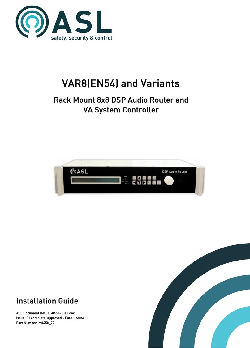
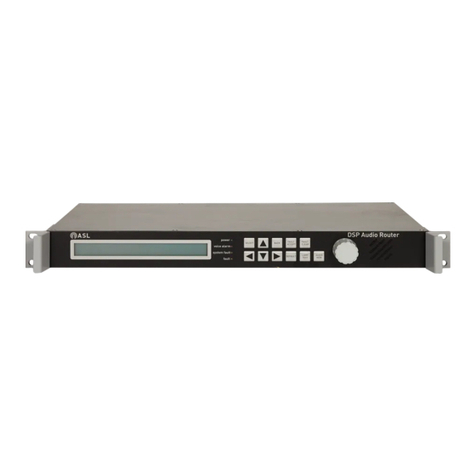
ASL INTERCOM VAR8-ACU Series User manual

VAR8-ACU and Variants
Audio Control Unit
ASL Document Ref.: U-0450-1430.doc
Issue: 3 - complete, approved - Date: 18/08/10
Part Number: M0450_54
Installation Guide

VAR8-ACU and Variants - Installation Guide
This equipment is designed and manufactured to conform to the following EC standards:
EMC EN55103-1/E1, EN55103-2/E5, EN50121-4, EN50130-4, EN61000-6-3,
ENV50204
Safety EN60065
Failure to use the equipment in the manner described in the product literature will
invalidate the warranty.
A 'Declaration of Conformity' statement to the above standards, and a list of auxiliary
equipment used for compliance verification, is available on request.
This product must be disposed of in accordance with the WEEE directive.
Copyright © 2007 Application Solutions Limited
Application Solutions Limited
Safety, Security and Control Division
Unit 17 Cliffe Industrial Estate
Lewes - East Sussex
BN8 6JL - UK
Tel: +44(0)1273 405411 Fax: +44(0)1273 405415
www.asl-electronics.co.uk
All rights reserved.
Information contained in this document is believed to be accurate, however no representation or warranty is given and
Application Solutions Limited assumes no liability with respect to the accuracy of such information.
Issue: 02 complete, approved
Page 2 of 22

VAR8-ACU and Variants - Installation Guide
Contents
1Installation ...................................................................................................................................... 5
1.1 Installation Requirements................................................................................................. 6
1.1.1 Cabling Requirements .............................................................................................. 6
1.2 Recommended Installation Procedure ............................................................................. 9
2Connections ................................................................................................................................. 11
3Product Specification .................................................................................................................. 14
4Mechanical Dimensions .............................................................................................................. 17
5Safety and Precautions ............................................................................................................... 18
5.1 Environmental................................................................................................................. 18
5.2 ESD ................................................................................................................................ 18
5.3 EMC................................................................................................................................ 18
5.4 Electrical Safety.............................................................................................................. 18
5.5 Lithium Battery................................................................................................................ 18
5.6 Unpacking and Handling ................................................................................................ 18
5.6.1 Packing for Repair .................................................................................................. 18
6Reference Documentation .......................................................................................................... 19
Service and Warranty.......................................................................................................................... 21
Issue: 02 complete, approved
Page 3 of 22

VAR8-ACU and Variants - Installation Guide
Document Change History
Issue Amendment Details Date
01 First Draft – Internal release 22/08/07
01.01 Internal release - Training 23/10/07
02 First release 14/012/07
Issue: 02 complete, approved
Page 4 of 22

VAR8-ACU and Variants - Installation Guide
1 Installation
The following drawing shows the standard base model VAR8-ACU connectors as well the Interface
Expansion Board connectors. Note that the Interface Expansion Board (EXP8) is an optional item.
Section “2 Connections” on page 11 describes the signals in each connector.
Figure 1 VAR8-ACU/Variant Connections
DOWNSTREAMUPSTREAM
NETWORK INTERFACE CARD (ANIC8)
V+NB
ACO1
V+NB
IN+
GND
0V
INPUT 4
DXP
V+NB
INPUT 6
V+
0V
DXN
IN+
IN-
DXP
DXN
DXN
DXP
DXN
DXP
V+
0V
IN+
IN-
DXN
V+NB
V+
0V
IN-
IN+
DXP
ACO2
SN2
INPUT 2
PTT2-
0V
V+
IN-
IN+
PTT2+
0V
DXP
DXN
V+
IN-
IN+
V+
PTT1-
PTT1+
SN1
IN-
IN+
C1+
GND
V+
5-8
A-
A+
CANH
CANL
RTS
CTS
CTRL
DXN
GND
COM
NC
NO
1-4
GND
RX
TX
DXP
C5+
C1-
C4+
C4-
C3+
C2+
C3-
C2-
C5-
AUDIO
OUTPUTS
INPUT 3 INPUT 5INPUT 1SERIAL
RS232
CONTROL
CONTACTS 5-1
FAULT
RELAY
SERIAL
RS232
AUDIO
OUTPUTS
AUDIO
MON
CAN
BUS
SERIAL
RS485
1 FAULT
2 FAULT
3 FAULT
1 FAULT
2 FAULT
3 FAULT
DOWN / UP
V+NB
V+
DXP
0V
DXN
IN+
IN-
V+NB
DXP
V+
DXN
0V
IN+
IN-
SCRN
DXP
DXN
BUS1+
BUS1-
BUS2+
BUS3-
BUS3+
BUS2-
GND
DXP
DXN
BUS1+
BUS1-
BUS2+
BUS3-
BUS3+
BUS2-
INPUT 8INPUT 7
MUSIC
1234
POWER
V+
V+
GND
GND
ON
C10+
C7-
C7+
C6-
C6+
C9+
C9-
C8+
C8-
C10-
CONTROL
CONTACTS 10-6
C20+
C17-
C17+
C16-
C16+
C19+
C19-
C18+
C18-
C20-
CONTROL
CONTACTS 20-16
C15+
C12-
C12+
C11-
C11+
C14+
C14-
C13+
C13-
C15-
CONTROL
CONTACTS 15-11
OUT1-A-
OUT3-A+
OUT4-A-
OUT4-A+
OUT2-A-
OUT1-A+
OUT3-A-
OUT2-A+
0V
A OUTPUTS 1-4
OUT5-A-
OUT7-A+
OUT8-A-
OUT8-A+
OUT6-A-
OUT5-A+
OUT7-A-
OUT6-A+
A OUTPUTS 5-8
OUT1-B-
OUT3-B+
OUT4-B-
OUT4-B+
OUT2-B-
OUT1-B+
OUT3-B-
OUT2-B+
0V
B OUTPUTS 1-4
OUT5-B-
OUT7-B+
OUT8-B-
OUT8-B+
OUT6-B-
OUT5-B+
OUT7-B-
OUT6-B+
B OUTPUTS 5-8
INTERFACE EXPANSION BOARD (EXP8)
DIP SW
DIP SW is used for maintenance only.
In operation, all switches should be on the OFF position, as shown in the drawing.
(INPUT 2)
(INPUT 1)
!
Issue: 02 complete, approved
Page 5 of 22

VAR8-ACU and Variants - Installation Guide
1.1 Installation Requirements
• The VAR8-ACU unit.
• A 19-inch standard rack and wiring for power supply, signal monitoring, and RS232 and RS485 cabling
as appropriate.
• A small flat-bladed screwdriver.
• Large pozidrive screwdriver.
• Cable termination tools - cutters/strippers etc. to suit cable type.
1.1.1 Cabling Requirements
The following cabling is recommended within the equipment rack. For pinout refer to Figure 1 (page 5), and
for cabling connector refer to Section “2 Connections” (page 11).
1. DC power supply cabling:
Standard cable rated for 3 A.
Recommended type: BELDEN 8205LSHF.
2. Audio input:
Twisted pairs, individually screened.
Recommended type: BELDEN 8451 LSHF.
The rack and field cabling should be as described in the diagram shown in Figure 3.
3. Audio and data network cabling:
Twisted pairs with overall foil screen.
Recommended type: FS cables 2407 POFYH.
The Upstream side of the network connection is isolated RS485. The rack and field cabling should be as
described in the diagram shown in Figure 2.
4. Other cabling:
Overall screened.
Recommended type: BELDEN LS0H.
The rack and field cabling should be as described in the diagram shown in Figure 3.
The use of screened cables where specified is necessary for EMC compliance. Also for EMC
compliance, rack and field cabling should be according to the specified diagram.
!
!
Issue: 02 complete, approved
Page 6 of 22

VAR8-ACU and Variants - Installation Guide
Figure 2 Network Termination
VAR8
NETWORK
UPSTREAM
BUS3-
BUS3+
BUS2-
BUS2+
BUS1-
BUS1+
DXN
DXP
GND
100 nF 100 V
(Reference: RS 211-5340)
DIN RAIL
FIELD CABLING RACK CABLING
NETWORK
DOWNSTREAM
DXN
DXP
SCREEN
BUS3-
BUS3+
BUS2-
BUS2+
BUS1-
BUS1+
DIN RAIL
FIELD CABLING RACK CABLING
!
SHORT CABLE TAIL
< 3 cm
!
Issue: 02 complete, approved
Page 7 of 22

VAR8-ACU and Variants - Installation Guide
Figure 3 Audio I/O and Other Signal Termination
DIN RAIL
EARTH TERMINAL
WEIDMÜLLER PART NUMBER: WPE4 SIGNAL TERMINAL
WEIDMÜLLER PART NUMBER: WDU2.5
DIN RAIL ELECTRONICALLY BONDED
TO THE RACK
!
SHORT CABLE TAIL
< 4 cm
RACK WIRING
FIELD WIRING
SCREEN
SCREEN
SHORT CABLE TAIL
< 3 cm
RACK EARTH TERMINAL
BONDED TO THE DIN RAIL
!
!
Issue: 02 complete, approved
Page 8 of 22

VAR8-ACU and Variants - Installation Guide
1.2 Recommended Installation Procedure
Please read and observe the “Safety and Precautions” section on page 18 of this manual.
1. Mount the VAR8-ACU into a 19-inch standard equipment rack.
DSP Audio Router
power
processor
comms
fault
SELECT BACK
DEFAULT LAMP
TEST
FAULT
CLEAR
FAULT
ACCEPT
AUDIO
MON
2U
M6 PAN HEAD POZIDRIV SCREW
M6 PLAIN WASHER
M6 CAGE NUT
Ensure that there is at least 1U of ventilated space between the unit and any source of heat
(e.g. V400 amplifier mainframes).
2. Connect the rack and field cabling for control ports, audio inputs, signal monitoring, RS232, and RS485,
as appropriate.
Wiring to each VAR8-ACU connector should be according to the diagram shown in
Figure 3 on page 7for EMC compliance.
!
!
!
!
!
!
The following drawings indicate the position of the connectors on the rear panel. Note that upper
connectors may not be present, depending on the VAR8-ACU variant being installed.
Figure 1 on page 5shows details of each connector. Section “2 Connections” on page 11 describes the
signals.
CONTROL PORTS
ADDITIONAL CONTROL PORTS
(ON EXP8 ONLY)
AUDIO INPUTS
Issue: 02 complete, approved
Page 9 of 22

VAR8-ACU and Variants - Installation Guide
RS232
RS485
FAULT RELAY
CAN BUS
AUDIO MONITORING
3. Connect the rack and field cabling for the network interface.
Wiring should be according to the diagram shown in Figure 2 on page 7 for EMC
compliance.
!
!
Figure 1 on page 5shows details of each connector. Section “2 Connections” on page 11 describes the
signals.
NETWORK UPSTREAM
NETWORK DOWNSTREAM
4. Connect the dual power supply (as appropriate) to the rear panel connector.
Section “2 Connections” on page 11 describes the signals.
POWER SUPPLY
GND +V GND +V
INPUT 1 INPUT 2
5. The installation is now complete and ready for system commissioning.
Refer to the Commissioning Guide [Table 1-3].
Issue: 02 complete, approved
Page 10 of 22

VAR8-ACU and Variants - Installation Guide
2 Connections
Network Interface Upstream
Signal Description
GND GND ISO. Connection for cable screen
DXP Data Bus+ (EIA RS485 38400 baud)
DXN Data Bus−(EIA RS485 38400 baud)
BUS1+ Audio bus Loop 1 (+20 dBu Analogue audio)
BUS1−Audio bus Loop 1
BUS2+ Audio bus Loop 2 (+20 dBu Analogue audio)
BUS2−Audio bus Loop 2
BUS3+ Audio bus Loop 3 (+20 dBu Analogue audio)
BUS3−Audio bus Loop 3
LCabling connector: 9 way female clamp terminal (CAMDEN CTB92HE/9)
Network Interface Downstream
Signal Description
SCRN Connection for cable screen
DXP Data Bus+ (EIA RS485 38400 baud)
DXN Data Bus−(EIA RS485 38400 baud)
BUS1+ Audio bus Loop 1 (+20 dBu Analogue audio)
BUS1−Audio bus Loop 1
BUS2+ Audio bus Loop 2 (+20 dBu Analogue audio)
BUS2−Audio bus Loop 2
BUS3+ Audio bus Loop 3 (+20 dBu Analogue audio)
BUS3−Audio bus Loop 3
LCabling connector: 9 way female clamp terminal (CAMDEN CTB92HE/9)
Audio Inputs 1 and 2
Signal Description
DXP Microphone Data+ (EIA RS485 19200 baud)
DXN Microphone Data−(EIA RS485 19200 baud)
0V 0 V supply
IN+ Balanced audio input +VE
Level: 0 dBu Max. Sensitivity: −20 dBu Input Impedance: 10 kΩ
IN−As above but −VE connection
V+ +V supply (18-36 V)
PTT−Press To Talk switch input (internally pulled up to +5 V by 4k7 Ω)
PTT+ Press To Talk switch input (internally pulled up to +5 V by 4k7 Ω)
ACO All Call Only LED. Open collector drive, 100 mA max
SN Speak Now LED. Open collector drive, 100 mA max
LCabling connector: 10 way terminal block (METWAY 120A11110)
Issue: 02 complete, approved
Page 11 of 22

VAR8-ACU and Variants - Installation Guide
Audio Inputs 3 to 8
Signal Description
DXP Microphone Data+ (EIA RS485 19200 baud)
DXN Microphone Data−(EIA RS485 19200 baud)
0V 0 V supply
IN+ Balanced audio input +VE
Level: 0 dBu Max. Sensitivity: −20 dBu Input Impedance: 10 kΩ
IN−As above but −VE connection
V+ +V supply (18-36 V)
V+NB Unused
LCabling connector: 7 way terminal block (METWAY 120A11107)
Music Input
Signal Description
GND Ground
IN+ Unbalanced audio input. Suitable for 1 V to 2 V RMS sources.
Impedance: 5 kΩ
LCabling connector: 2 way terminal block (METWAY 120A11102)
Standard Audio Outputs
RJ45 connectors ‘OUT’ are not used by VAR8-ACU.
Enhanced A/B Audio Outputs
Terminal blocks ‘A OUTPUTS 1-4’, ‘A OUTPUTS 5-8’, ‘B OUTPUTS 1-4’, and ‘B OUTPUTS 5-8’ on EXP8
Interface Expansion Board are not used by VAR8-ACU.
Control Contacts – Digital Inputs
Signal Description
C'n'+ Opto-isolated input +VE connection
Cn'−As above but –VE connection
Built-in resistor to suit voltages of +12 to +40 V
LContacts 1 to 10 may have EOL resistors internally fitted.
LCabling connector: 10 way terminal block (METWAY 120A11110)
RS485 Serial Port
Signal Description
GND 0 V Reference
DXN Data+ (EIA RS485 9600 baud)
DXP Data– (EIA RS485 9600 baud)
LCabling connector: 3 way terminal block (METWAY 120A11103)
Issue: 02 complete, approved
Page 12 of 22

VAR8-ACU and Variants - Installation Guide
CAN Bus
Terminal block ‘CAN’ is not used by VAR8-ACU.
RS232 Serial Port
Signal Description
GND 0 V Reference
TX EIA RS232 Transmit data (9600 baud)
RX EIA RS232 Receive data (9600 baud)
RTS EIA RS232 Request to Send
CTS EIA RS232 Clear to Send
CTRL EIA RS232 Data Terminal Ready
LCabling connector: 2 x 3 way terminal block (METWAY 120A11103)
Fault Relay Contacts
Signal Description
NO Volt free contact – Normally Open
COM Relay Common
NC Volt free contact – Normally Closed
LCabling connector: 3 way terminal block (METWAY 120A11103)
Auxiliary Supply
Signal Description
V+ Auxiliary supply: 18 V to 36 V fused at 200 mA
A−Unused
A+ Unused
LCabling connector: 3 way terminal block (METWAY 120A11103)
Power Supply
Signal Description
V+ +V supply (18 V to 40 V DC fused at 2.5 A)
GND 0 V supply
LTwo alternate power inputs.
LCabling connector: 4 way terminal block (METWAY 120A11104)
Issue: 02 complete, approved
Page 13 of 22

VAR8-ACU and Variants - Installation Guide
3 Product Specification
General
Supply Voltage Range..............................................................................................................18 to 40 V DC
Current Consumption ...........................................500 mA @ 24 V DC supply, backlight off and sounder off
610 mA @ 24 V DC supply, backlight on and sounder on
Auxiliary DC supply for external equipment ..........................................................18 to 36 V DC @ 200 mA
Fault Log........................................................................................................................................200 events
Real Time Clock (RTC) ........................................................................... Built-in (externally synchronisable)
Format ...............................................................................................................19-inch rack mounting frame
Field Connections..............................................................................................................Screw-in terminals
Colour ..................................................................................................................Black with silver annotation
Audio Input
Number of Balanced Audio Inputs............................................................................................................. 81,2
Sensitivity and Impedance: −20 dBu (77 mV) @ Z ≥20 kΩ
Number of Unbalanced Audio Input ..............................................................................................................1
Sensitivity and Impedance: Suits 1–2 V RMS units Z ≥5 kΩ
Input Overload Margin........................................................................................................................... 40 dB
Input Attenuator Range ................................................................................................................ 0 to –63 dB
Equalisation ......................................................................................................................3 band plus LF Cut
Surveillance Tone......................................................................20 to 30 Hz / Required Level 0 to –40 dBFS
Network Output
Outputs .....................................................................................................................................Outputs 1 to 3
Level ..................................................................................................................................................+20 dBu
Graphic Equalisation .......................................................±12 dB @ 125, 250, 500, 1 k, 2 k, 4 k, 8 k, 16 kHz
Surveillance Tone..............................................................................................................10 dBu to –30 dBu
30 Hz Continuous
Gain Control Range.................................................................................................................0 dB to −63 dB
DVA
Number of Digital Messages (DVA) ......................................................................... 2x50-second messages
2x66-second messages
DVA Bandwidth .....................................................................................................................100 Hz to 8 kHz
1Inputs 1 and 2: Hardwire bypass Fire Microphone inputs.
Support Fire Microphone, Zoned Fire Microphone, Paging Microphone, Single Button Microphone, or
Miscellaneous Input.
Support up to 30 microphone buttons.
2Inputs 3 to 8: Support Paging Microphone, Single Button Microphone, or Miscellaneous Input.
Support up to 20 microphone buttons.
Issue: 02 complete, approved
Page 14 of 22

VAR8-ACU and Variants - Installation Guide
Audio General
THD Input to Output .............................................................................................................. <0.1 % @1 kHz
Crosstalk................................................................................................................................ >70 dB @1 kHz
Residual Noise ............................................................................................................................ <78 dBu (A)
S/N Line......................................................................................................................................... >70 dB (A)
Frequency Response (Input to Output)................................................................... 100 Hz to 20 kHz, –3 dB
Audio Monitoring
SPL from Loudspeaker (Sounder Mode) ...................... ≥50 dBA @ 1 m from the equipment enclosure
Frequency Response (From Input through to Speaker)................................... 200 Hz to 10 kHz −3 dB
Gain Range Control (Front panel rotary encoder)................................................................ 0 to –63 dB
Audio Routing
Number of Concurrent Host Routes ................................................................................................ 20 (max.)
Number of Concurrent ACU-Instigated Routes...........................................................................................50
Override per Output......................................................................................................................... 40 (max.)
Control Ports
Digital Inputs
Number of Digital Inputs.............................................................................................................. 10 on VAR8
20 on VAR8-E
Interface.................................................. Opto-isolated with built-in resistor to suit voltages of +12 to +40 V
Others
Open Collector Drive (SPEAK NOW LED, ALL CALL LED) .............................................................. 100 mA
Changeover Fault Relay................................................................................................................................1
Maximum Global Fault Relay Contact Current Rating: 500 mA
RS485 Port ....................................................................................................................................................1
Up to 6 Remote I/O Units (BMB01)
RS232 Port ....................................................................................................................................................1
For mutually exclusive use by Host PC for configuration, Intellevac Network3
VAR8-ACU Variants
VAR8-ACU .....................................................................Base Unit, standard 8x8 Audio Control Unit Router
EXP8..................................................................................................................... Interface Expansion Board
Factory fit option ordered with VAR8-ACU
Network
Network Audio Channels................................................................................................................... 1, 2 or 3
Standard ...............................................................................................................................................RS485
Data Rate.......................................................................................................................................38.4 kbaud
Distance between Nodes..............................................................................................................1 km (max.)
Network Control Response Time (Fire Alarm trigger to DVA initiation) .........................................<1 second
Fault tolerance................................................Any single open or short circuit can be detected and isolated
3The RS232 port is internally used for system networking. It may be temporarily disconnected from the network, and connected to a
Host PC for configuration purposes.
Issue: 02 complete, approved
Page 15 of 22

VAR8-ACU and Variants - Installation Guide
Dimensions and Weight
Dimensions (H x W x D) .......................... 88 mm (2U) x 436 mm x 233 mm (excl. connectors and handles)
Weight....................................................................................................................................................4.5 kg
Environmental – All Variants
Temperature (Storage and Operating) ............................................................................. −5 °C up to +50 °C
Humidity Range ................................................................................................0 % to 93 % Non-condensing
Safety and EMC
EMC........................... EN55103-1/E1, EN55103-2/E5, EN50121-4, EN50130-4, EN61000-6-3, ENV50204
Safety................................................................................................................................................EN60065
Issue: 02 complete, approved
Page 16 of 22

VAR8-ACU and Variants - Installation Guide
4 Mechanical Dimensions
DSP Audio Router
power
processor
comms
fault
SELECT BACK
DEFAULT LAMP
TEST
FAULT
CLEAR
FAULT
ACCEPT
AUDIO
MON
436 mm
483 mm
88 mm (2U)
263 mm
233 mm
222 mm
263 mm
233 mm
222 mm
88 mm
47.2 mm
88 mm
20 mm
THIRD ANGLE PROJECTION
Issue: 02 complete, approved
Page 17 of 22

VAR8-ACU and Variants - Installation Guide
5 Safety and
Precautions
5.5 Lithium Battery
Danger of explosion if battery is
incorrectly replaced. Replace only
with the same or equivalent type.
Dispose of battery carefully to avoid
environmental damage. Do not
dispose of battery in a fire.
5.1 Environmental
The temperature and humidity ranges shown in
the specifications for this product must not be
exceeded.
This equipment must not be installed in an area
that is subject to a corrosive atmosphere,
excessive moisture or may allow water or other
liquids to come into contact with the unit or its
external connections.
5.6 Unpacking and Handling
The equipment should be unpacked and
inspected immediately on receipt. If damage has
occurred please advise your carrier or supplier.
In the close proximity of some radio frequency
transmitters, the signal to noise ratio of this
product may be reduced. If this occurs, re-location
of the equipment or the signal cables is
recommended.
It is advisable to retain the original equipment
packing in the event that the equipment ever
needs returning for service.
Ensure that the name and address of the
Authorised Distributor from whom you purchased
the unit is recorded on the "Service and Warranty"
page of this manual for future reference.
5.2 ESD
This product contains static-sensitive devices.
Observe ESD precautions when working on the
equipment with the cover removed. 5.6.1 Packing for Repair
All electronics assemblies must be
properly packed in ESD protective
packing for transport, to prevent
physical and ESD damage. Use of
non-ESD protective packing for return
for repair or service will automatically
invalidate the warranty.
5.3 EMC
EMC compliance is dependent on this unit being
wired in accordance with these installation
instructions.
5.4 Electrical Safety
The filler material used for packing for
return for repair must be antistatic or
static dissipative, as this may come
into contact with exposed connectors,
wiring, or PCB assemblies. The use
of non-conductive filler material may
cause damage to the electronic
assemblies reducing their operational
life, or even destroying them, and it
will automatically invalidate the
warranty.
Always replace blown fuses with the
correct type and rating.
Ensure adequately rated cables are
used for power supply.
!
!
!
!
!
!
!
!
!
!
Advice on packing the product for return can be
provided by Application Solutions Limited.
Issue: 02 complete, approved
Page 18 of 22

VAR8-ACU and Variants - Installation Guide
6 Reference Documentation
Additional reference information may be found in the following documentation, available from the “Data
Downloads” page of Application Solutions website: www.asl-electronics.co.uk
Table 1 Reference Documents
Ref. No Title Filename Ref Origin
1 VAR8-ACU / Variants Product Description U-0450-1431 ASL
2 VAR8-ACU / Variants Installation Guide (this document) U-0450-1430 ASL
3 VAR8-ACU / Variants Commissioning and Operation Guide Refer to ASL quoting the
SW version of your unit
for appropriate guide
ASL
4 VAR8 / Variants Product Manual U-0450-1361 ASL
5 VAR8 / Variants Installation Guide U-0450-1360 ASL
6 VAR8 / Variants Commissioning and Operation Guide Refer to ASL quoting
the SW version of
your unit for
appropriate guide
ASL
7 VA Amplifier Products Equipment Handbook 398A_Amp_Handbook ASL
8 V400 Mainframe Installation Guide 398A_V400_Guide.doc ASL
9 DMS5/10 Digital Microphone Stations Technical Installation
Guide
464_dms_guide ASL
10 DMS20 Digital Microphone Stations Technical Installation
Guide
U-0464-0224 ASL
11 FMS1 All-Call Fireman's Microphone Technical Installation
Guide
464_FMS1_Guide ASL
12 FMS5/10/20 Zoneable Fireman's Microphones Technical
Installation Guide
464_FMS5_10_20_Guide ASL
13 BMB01 Router I/O Expander Installation Guide 450_bmb01_guide ASL
Issue: 02 complete, approved
Page 19 of 22

VAR8-ACU and Variants - Installation Guide
Page intentionally left blank.
Issue: 02 complete, approved
Page 20 of 22
Other manuals for VAR8-ACU Series
1
Table of contents
Other ASL INTERCOM Network Router manuals