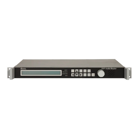
ASL INTERCOM VAR8 Technical specifications

VAR8 and Variants
Audio Router and System Controller
ASL Document Ref.: U-0450-1360.doc
Issue: 02 - complete, approved - Date: 18/08/10
Part Number: M0450_51
Product Description

VAR8 and Variants - Product Description
Copyright © 2007 Application Solutions Limited
Application Solutions Limited
Safety, Security and Control Division
Unit 17 Cliffe Industrial Estate
Lewes - East Sussex
BN8 6JL - UK
Tel: +44(0)1273 405411 Fax: +44(0)1273 405415
www.asl-electronics.co.uk
All rights reserved.
Information contained in this document is believed to be accurate, however no representation or warranty is given and
Application Solutions Limited assumes no liability with respect to the accuracy of such information.
Issue: 02 complete, approved
Page 2 of 54
This equipment is designed and manufactured to conform to the following EC standards:
EMC EN55103-1/E1, EN55103-2/E5, EN50121-4, EN50130-4, EN61000-6-3,
ENV50204
Safety EN60065
Failure to use the equipment in the manner described in the product literature will
invalidate the warranty.
A ‘Declaration of Conformity’ statement to the above standards, and a list of auxiliary
equipment used for compliance verification, is available on request.
This product must be disposed of in accordance with the WEEE directive.

VAR8 and Variants - Product Description
Issue: 02 complete, approved
Page 3 of 54
Contents
1Overview ................................................................................................................................................... 5
2Router Functions ................................................................................................................................... 10
2.1 Audio Inputs.............................................................................................................................. 10
2.1.1 Mic/Line Inputs.................................................................................................................. 10
2.1.1.1 Paging Microphone Mode ......................................................................................... 11
2.1.1.2 Fire Microphone (ALL-CALL) Mode .......................................................................... 11
2.1.1.3 Zoneable Fire Microphone Mode .............................................................................. 11
2.1.1.4 Single Button Microphone Mode............................................................................... 12
2.1.1.5 Miscellaneous Input Mode ........................................................................................ 12
2.1.1.6 Network Channel Mode............................................................................................. 12
2.1.1.7 Unused Mode............................................................................................................ 12
2.1.2 Digital Voice Announcers.................................................................................................. 13
2.1.3 Music Input........................................................................................................................ 13
2.1.4 Mute Input ......................................................................................................................... 13
2.2 Audio Outputs........................................................................................................................... 13
2.3 Audio Input Priority and Override ............................................................................................. 14
2.4 Fades and Chimes ................................................................................................................... 15
2.4.1 Fades ................................................................................................................................ 15
2.4.2 Chimes.............................................................................................................................. 15
2.4.3 Sequence of Events.......................................................................................................... 15
2.5 Surveillance Tone Detection and Generation........................................................................... 17
2.5.1 Detection........................................................................................................................... 17
2.5.2 Generation ........................................................................................................................ 17
2.6 Control ...................................................................................................................................... 17
2.6.1 Contacts............................................................................................................................ 18
2.6.1.1 Opto-Isolated Interface.............................................................................................. 18
2.6.1.2 Contact Functions ..................................................................................................... 19
2.6.1.2.1 Routing: Latching............................................................................................... 19
2.6.1.2.2 Routing: Non-Latching, Latent Routes .............................................................. 20
2.6.1.2.3 External Faults................................................................................................... 20
2.6.2 Permanent Routes............................................................................................................ 21
2.6.3 Remote I/O Units .............................................................................................................. 21
2.6.3.1 RS485 Connections .................................................................................................. 21
2.6.3.2 Remote I/O Unit Functionality Summary................................................................... 22
2.6.3.3 Analogue Inputs ........................................................................................................ 22
2.6.3.3.1 Programme Selector Operation......................................................................... 23
2.6.3.3.2 Volume Control Operation................................................................................. 23
2.6.3.3.3 Ambient Noise Sensors (ANS) .......................................................................... 24
2.6.3.4 Digital Inputs ............................................................................................................. 25
2.6.3.5 Digital Outputs........................................................................................................... 25
2.7 Night Time Volume Control ...................................................................................................... 26
3Network ................................................................................................................................................... 27
3.1 Network Operation.................................................................................................................... 27
3.1.1 Data Network ....................................................................................................................27
3.1.2 Audio Network...................................................................................................................27
3.2 Network Topology..................................................................................................................... 28
3.2.1 4x4 ACU Network Topology ............................................................................................. 28
3.2.1.1 System Parameters................................................................................................... 29
3.2.1.2 Main Network Features ............................................................................................. 29
3.2.2 8x8 ACU Network Topology ............................................................................................. 30
3.2.2.1 System Parameters................................................................................................... 30
3.2.2.2 Main Network Features ............................................................................................. 30
4Control and Indicators........................................................................................................................... 32
4.1 LCD Backlight Control .............................................................................................................. 33
5Fault Monitoring..................................................................................................................................... 34

VAR8 and Variants - Product Description
Issue: 02 complete, approved
Page 4 of 54
5.1 Indication, Acceptance, and Clearance.................................................................................... 34
5.1.1 Fault Indication.................................................................................................................. 34
5.1.2 Fault Acceptance .............................................................................................................. 34
5.1.3 Fault Clearance.................................................................................................................35
5.1.4 Current Faults ................................................................................................................... 35
5.2 Fault Logging............................................................................................................................ 35
5.3 Fault Relay................................................................................................................................ 36
6Test Functions........................................................................................................................................ 37
7Mechanical Dimensions ........................................................................................................................ 38
8Connector Signals and Pinout.............................................................................................................. 39
8.1 Network Interface ..................................................................................................................... 40
8.2 Audio Inputs.............................................................................................................................. 41
8.3 Audio Outputs........................................................................................................................... 43
8.3.1 Standard Audio Outputs ................................................................................................... 43
8.3.2 Enhanced A/B Audio Outputs ........................................................................................... 43
8.4 Digital Inputs (Control Contacts)...............................................................................................44
8.5 RS485 Serial and CAN Bus...................................................................................................... 45
8.6 RS232 Serial............................................................................................................................. 45
8.7 Fault Relay, Audio Monitoring Bus, and Auxiliary Supply ........................................................ 46
8.8 DC Power Input ........................................................................................................................ 46
9Product Specification ............................................................................................................................ 47
10 Reference Documentation .................................................................................................................... 50
11 Abbreviations ......................................................................................................................................... 51
12 Index........................................................................................................................................................ 52
Service and Warranty.................................................................................................................................... 53
Document Change History
Issue Amendment Details Date
01 First Draft 13/09/07
02 First Release 14/12/07

VAR8 and Variants - Product Description
Issue: 02 complete, approved
Page 5 of 54
1 Overview
The VAR8 and its variants are DSP-based Audio Routers, allowing routing of audio inputs to any
combination of their outputs. In addition to audio routing, the VAR8 provides full system control and fault
reporting functions for the Application Solutions rack mount Voice Alarm systems.
The control functions include the monitoring and control of up to 63 V400 Amplifier Mainframes, associated
amplifiers, and surveillance interface cards. Each Mainframe connects to the VAR8 via an Audio-CANTM
serial data network and audio monitor bus.
The VAR8 is the base unit, which can be optionally supplied with an EXP8 Interface Expansion Board, an
EFI01 European Fire Interface Card, and/or an ANIC Network Interface Card.
The VAR8 base unit has the following audio I/O:
• Audio inputs:
− 8 universal Mic/Line inputs, which can support multi-zone ASL Paging Microphones
− Mic/Line inputs 1 & 2 can support All-Call or zoneable Fire Microphones, which act as all-call
hardware bypass microphones in the event of processor failure, as required by BS5839 Pt 8.
− 1 additional input for miscellaneous functions e.g. background music.
• Audio outputs:
8 single audio outputs (not A+B pairs), for feeding amplifiers.
• Digital messages (DVA):
Two 66-second messages (DVA1 & DVA2) and two 50-second messages (DVA3 & DVA4).
• Audio monitoring input:
Additional balanced audio input for audio monitoring of amplifier outputs.
The VAR8 built-in fire alarm interfaces include:
• 10 opto-isolated sounder circuit inputs, suitable for connecting fire alarm panels to the VAR8 for the
purpose of triggering digital messages.
• RS485 serial interface for connection of Fire Loop Interfaces.
• Common fault output relay.
The Intellevac Network Interface Card (ANIC) provides networking capability to the VAR8 with the following
features:
• Interface to a network hosted by an Intellevac ACU Audio Control Unit or a VAR8-ACU Audio Control
Unit.
• Announcements and DVAs initiated from the Audio Control Unit, or any microphone connected to it,
may be broadcast to the VAR8 outputs.
• Inputs 1, 3, and 4 of VAR8 are normally used for the network connections.
• Section “3 Network” describes the network features and operation.
The Interface Expansion Board (EXP8) provides the following additional features to the VAR8-E:
• Separate A and B audio output connections, for driving A+B amplifiers with interleaved speaker
circuits.
• 10 additional opto-isolated inputs.
The European Fire Interface Card (EFI01) replaces the VAR8 base unit’s opto-isolated inputs with:
• 8 non-isolated analogue inputs.
• 8 open-collector digital outputs.
• The EXP8 opto-isolated inputs are not affected by the EFI01.

VAR8 and Variants - Product Description
Issue: 02 complete, approved
Page 6 of 54
Table 1 summarises the VAR8 variants and optional items.
Built-in routing and general control inputs enable interfacing to advanced DVA or site control systems. A
serial control port gives the VAR8 the ability to be remotely monitored and configured.
The VAR8 also has a front panel display and control interface, that provides functions for system
commissioning, fault monitoring, and audio monitoring. Alteration of the system configuration is controlled by
an access code.
For detailed information on the Intellevac ACU Audio Control Unit and VAR8-ACU, please refer to the their
specific documentation, [Table 5].
Table 1 VAR8, Variants, and Optional Items
Variant Description
VAR8 Base Unit, standard 8x8 Router
VAR8-E VAR8+EXP8 Interface Expansion Board
ANIC Intellevac Network Interface Card
Factory fit option ordered with VAR8 or VAR8-E.
EFI01 European Fire Interface Card (Analogue Input and Digital Output)
Factory fit option ordered with VAR8 or VAR8-E.

VAR8 and Variants - Product Description
Issue: 02 complete, approved
Page 7 of 54
Figure 1 VAR8 and Variants – Diagram
DVA
MESSAGE-3
DVA
MESSAGE-2
DVA
MESSAGE-1
INPUT-5
INPUT-4
INPUT-3
INPUT-2
INPUT-1
RS232
CONTROL
USER
INTERFACE
MUSIC
INPUT-8
INPUT-7
INPUT-6
INTELLEVAC
NETWORK
INTERFACE
CARD
(ANIC8)
CONTROL
INTERFACES
VAR8
BASE UNIT
VAR8: BASE UNIT
VAR8-E: BASE UNIT + INTERFACE EXPANSION BOARD
ANIC8: INTELLEVAC NETWORK INTERFACE CARD (FACTORY FIT OPTION)
EFI01: EUROPEAN FIRE INTERFACE CARD (FACTORY FIT OPTION)
*) EFI01 ANALOGUE INPUTS AND DIGITAL OUTPUTS REPLACE VAR8
BASE UNIT DIGITAL INPUTS
INTERFACE
EXPANSION
BOARD
(EXP8)
A
B
A
B
A
B
A
B
A
B
A
B
A
B
A
B
INPUT-5
INPUT-4
INPUT-3
INPUT-2
INPUT-1
MUSIC
INPUT-8
INPUT-7
INPUT-6
SINGLE AUDIO OUTPUTS A+B PAIR AUDIO OUTPUTS
AUDIO INPUTSINTELLEVAC NETWORK
A
A
A
A
A
A
A
A
OUTPUT-1
OUTPUT-2
OUTPUT-3
OUTPUT-4
OUTPUT-5
OUTPUT-6
OUTPUT-7
OUTPUT-8
OUTPUT-1
OUTPUT-2
OUTPUT-3
OUTPUT-4
OUTPUT-5
OUTPUT-6
OUTPUT-7
OUTPUT-8
HARDWARE AUDIO BYPASS
DVA
MESSAGE-4
AUDIO
ROUTING
MATRIX
CONTACTS
DIGITAL INPUTS
DIGITAL INPUTS *)
RS485
EUROPEAN
FIRE
INTERFACE
(EFI01)
CONTACTS
ANALOGUE INPUTS
DIGITAL OUTPUTS
DOWNSTREAM
UPSTREAM

VAR8 and Variants - Product Description
Issue: 02 complete, approved
Page 8 of 54
Figure 2 VAR8/VAR8-E Application Example
OUTPUT 1
AB*
*) B outputs available on EXP8
Interface Expansion Board
AB* AB*
OUTPUT 8
FMS10
FIRE MICROPHONE
DMS10
PAGING MICROPHONE BACKGROUND MUSIC
VAR8
V400
AMPLIFIER MAINFRAME
SPEAKER CIRCUITS
A
B
BMB01
REMOTE I/O UNIT
AMBIENT NOISE SENSOR
PROGRAMME SELECTOR
VOLUME CONTROL
LOCAL
FIRE
ALARM
PANEL
Figure 3 VAR8/VAR8-E Network Application Network with Intellevac ACU
ALERT
EVACUATE
MIC
DATA
V400
AMPLIFIER MAINFRAME
SPEAKER CIRCUITS
A
AB*
*) B outputs available on EXP8
Interface Expansion Board
AB* AB*
OUTPUT 8
FMS10
LOCAL
FIRE MICROPHONE
DMS10
LOCAL
PAGING MICROPHONE
LOCAL
BACKGROUND MUSIC
B
EVACUATE
ALERT
MIC
DATA
AB*
*) B outputs available on EXP8
Interface Expansion Board
AB* AB*
OUTPUT 8
DMS10
LOCAL
PAGING MICROPHONE
LOCAL
BACKGROUND MUSIC
EVACUATE
ALERT
MIC
DATA
DMS20
CENTRAL
PAGING MICROPHONE
CENTRAL
BACKGROUND
MUSIC
AUDIO RING (3x)
DATA RING (1x)
ACU
AUDIO CONTROL UNIT
AND CONTROL
EMERGENCY
MICROPHONE
VAR8
INTELLEVAC EMERGENCY
NETWORK
OUTPUT 1
V400
AMPLIFIER MAINFRAME
SPEAKER CIRCUITS
A
B
OUTPUT 1
VAR8
BMB01
REMOTE I/O UNIT
AMBIENT NOISE SENSOR
PROGRAMME SELECTOR
VOLUME CONTROL
LOCAL
FIRE
ALARM
PANEL
CENTRAL
FIRE
ALARM
PANEL

VAR8 and Variants - Product Description
Issue: 02 complete, approved
Page 9 of 54
Figure 4 VAR8/VAR8-E Network Application Network with VAR8-ACU
V400
AMPLIFIER MAINFRAME
SPEAKER CIRCUITS
A
AB*
*) B outputs available on EXP8
Interface Expansion Board
AB* AB*
OUTPUT 8
FMS10
LOCAL
FIRE MICROPHONE
DMS10
LOCAL
PAGING MICROPHONE
LOCAL
BACKGROUND MUSIC
B
EVACUATE
ALERT
MIC
DATA
AB*
*) B outputs available on EXP8
Interface Expansion Board
AB* AB*
OUTPUT 8
DMS10
LOCAL
PAGING MICROPHONE
LOCAL
BACKGROUND MUSIC
EVACUATE
ALERT
MIC
DATA
AUDIO RING (3x)
DATA RING (1x)
VAR8
VAR8
BMB01
REMOTE I/O UNIT
AMBIENT NOISE SENSOR
PROGRAMME SELECTOR
VOLUME CONTROL
OUTPUT 1
V400
AMPLIFIER MAINFRAME
SPEAKER CIRCUITS
A
B
OUTPUT 1
LOCAL
FIRE
ALARM
PANEL
ALERT
EVACUATE
MIC
DATA
VAR8-ACU
VAR8 AUDIO CONTROL
UNIT
DMS20
CENTRAL
PAGING MICROPHONE
CENTRAL
BACKGROUND
MUSIC
FMS10
CENTRAL
FIRE MICROPHONE
CENTRAL
FIRE
ALARM
PANEL
INTELLEVAC EMERGENCY
NETWORK

VAR8 and Variants - Product Description
Issue: 02 complete, approved
Page 10 of 54
2 Router Functions
2.1 Audio Inputs
The Router has eight electronically balanced line level inputs. Each of these inputs features a serial
communications interface, which allows any ASL microphones to be connected.
The first two of these inputs can also be used for ASL emergency or Fireman’s Microphones in Voice Alarm
systems, this is because they have the facility for an analogue bypass mode in the event of processor
failure/mis-operation, as required by BS5839 Pt 8. In the event of processor failure or communication failure,
the operation reverts to All-Call mode. These two inputs also support DVA routing for triggering DVA
messages.
A ninth, unbalanced, input is also provided, typically for background music applications. Refer to Section
“2.1.3 Music Input”.
The Router provides a special input for muting any other input, even fire microphones. Refer to Section
“2.1.4 Mute Input”.
The Router provides four Digital Voice Announcer (DVA) Messages; these are treated as additional inputs to
the routing matrix. Refer to Section “2.1.2 Digital Voice Announcers”.
All inputs described above feed a DSP Audio Routing Matrix. Audio is soft-switched to prevent clicks, and
fade times can be assigned in order to improve the performance for background music applications.
2.1.1 Mic/Line Inputs
Each of the Mic/Line Inputs may be configured for a particular input type. The following sections describe the
operation and routing of each input type. Table 2 summarises the Mic/Line input capabilities.
Table 2 Mic/Line Input Capabilities
Inputs Available Input Types Microphone Buttons Router Applicability
ASL Fire Microphone N/A
ASL Zoned Fire Microphone
ASL Paging Microphone
Up to 30 microphone buttons,
configurable for zone select, DVA
routing, play DVA, all call, cancel-all-
DVAs, route reset.
ASL Single Button Microphone PTT routing.
Miscellaneous Input N/A
Network Channel N/A
Option available only on Input 1.
Input 1 is normally used for
network operation.
1 and 2
Unused N/A Input is excluded from routing
and audio monitoring.
ASL Paging Microphone
Up to 20 microphone buttons,
configurable for zone select, play
DVA, all call, cancel-all-DVAs, route
reset.
ASL Single Button Microphone PTT routing.
Miscellaneous Input N/A
Network Channel N/A
Option available only on Inputs
3 and 4.
Inputs 3 and 4 are normally
used for network operation.
3 to 8
Unused N/A Input is excluded from routing
and audio monitoring.

VAR8 and Variants - Product Description
Issue: 02 complete, approved
Page 11 of 54
2.1.1.1 Paging Microphone Mode
It is possible to set any of the Mic/Line inputs for Paging Microphone operation. When configured for this
mode of operation, any ASL Paging Microphone can be supported. For example: DMS5, DMS10, DMS20.
These units are desk consoles that provide zone selection buttons and indicators to show which buttons are
selected and which zones are currently ‘busy’ i.e. in use by another user. The zone selection buttons are
programmable by the Router to correspond to the required outputs or groups of outputs.
If a Paging Microphone is connected to inputs 1 or 2 the zone selection buttons are also programmable by
the VAR Router for DVA Routing. The primary function is triggering DVAs although it can connect any
desired combination of inputs to outputs. The operation and configuration are similar to that of Latent
Routes; see Section “2.6.1.2 Contact Functions”.
The button and LED data is communicated between the Microphone and Router by means of a dedicated
RS485 data link provided on each Mic/Line input.
2.1.1.2 Fire Microphone (ALL-CALL) Mode
Fire Microphone operation is configurable for inputs 1 & 2 only. Any ASL All-Call Fire Microphone may then
be connected. For example: FMS1, EAP01.
All-Call Microphones do not need a serial interface. However, the serial interface may be installed if a busy
LED function is required. These microphones have a hardwired PTT switch interfaced to the Router, this
switch is provided with resistors to allow the cabling to be monitored for faults by the Router.
A hardwired SPEAK-NOW LED is also provided. Operation is as described below:
Normal Operation: In normal operation, all-call is initiated by the controller monitoring the state of the
contact and routing audio via the DSP to all outputs.
A SPEAK-NOW LED is provided on the Fire Microphone, and is driven by the processor
once the route is made (and chime has sounded).
Failsafe Operation: If the Router detects processor failure or mis-operation, a hardware bypass mode comes
into operation for the Fire Microphones.
When the PTT is pressed, an all-call analogue bypass path is driven which bypasses all
processor controlled elements.
The SPEAK-NOW LED is illuminated on the Fire Microphone once the route is made.
2.1.1.3 Zoneable Fire Microphone Mode
Zoneable Fire Microphone operation is configurable for inputs 1 & 2 only. Any ASL Zoneable Fire
Microphone may then be connected. For example: FMS5, FMS10, FMS20.
The zone selection buttons are also programmable by the VAR Router for DVA Routing. The primary
function is triggering DVAs although it can connect any desired combination of inputs to outputs. The
operation and configuration are similar to that of Latent Routes; see Section “2.6.1.2 Contact Functions”.
The Zoneable Fire Microphones use the same serial control interface as the Paging Microphones to
communicate button and LED status.
As well as a serial interface, a hardwired PTT switch is interfaced to the Router. This switch is provided with
resistors to allow the cabling to be monitored for faults.
A hardwired SPEAK-NOW LED and ALL-CALL-ONLY LED are also provided. Operation is as described
below:
Normal Operation: In normal operation, all routes are set up via the serial interface, and audio is routed via
the DSP. The hardware ALL-CALL contact is used as the PTT in order to provide
BS5839 functionality.
A hardwired speak-now LED is illuminated on the Fire Microphone once the route is
made (and chime has sounded).

VAR8 and Variants - Product Description
Issue: 02 complete, approved
Page 12 of 54
Failsafe Operation: If the Router detects processor failure or mis-operation, a hardware bypass mode comes
into operation for the Fire Microphones. When this happens the Router provides an ALL-
CALL-ONLY signal back to the Fire Microphone, which illuminates the ALL-CALL-ONLY
LED on the Fire Microphone panel. When the PTT is pressed, an all-call analogue
bypass path is driven which bypasses all processor controlled elements.
The hardwired SPEAK-NOW LED is illuminated on the Fire Microphone once the route is
made.
If the RS485 communications link fails but the Router processor is running correctly the
ALL-CALL-ONLY LED is illuminated and operation reverts to all-call. However in this
case the audio is still routed through the DSP.
2.1.1.4 Single Button Microphone Mode
It is possible to set any of the Mic/Line inputs for Single Button Microphone Operation. For example: SAP01,
and SAP02.
A Single Button Microphone provides indicators and PTT button. The PTT button can be programmed for
zone selection at the Router to correspond to certain outputs or groups of outputs.
The button and LED data is communicated between the Microphone and Router by means of a dedicated
RS485 data link provided on each Mic/Line input.
2.1.1.5 Miscellaneous Input Mode
It is possible to set any of the Mic/Line inputs as Miscellaneous Input Mode. When configured for this mode
of operation, the serial communication interface is disabled and other type of audio input may be connected,
e.g. PC/DVA audio, Long Line PA (LLPA) audio, or an additional background music input. The audio may be
routed by the Permanent Route or Latent Contact Route mechanisms, described in Section “2.6 Control”.
2.1.1.6 Network Channel Mode
By default if a Network Interface Card is fitted in the VAR8 then it will use Router Inputs as follows:
• Network Channel 1 – Router Input 1
• Network Channel 2 – Router Input 3
• Network Channel 3 – Router Input 4
This is the Intellevac Network standard configuration with 3 network audio channels.
It is possible to implement fewer network channels where concurrent broadcast of ALERT, EVACUATE and
Fire Microphone audio is not required. The corresponding VAR8 Inputs would then be available for
connection of local microphones or other audio sources.
Network operation with fewer audio channels is configured by programming the Router, and adjusting the
hardware settings on the Network Interface Card.
2.1.1.7 Unused Mode
It is possible to set any of the Mic/Line inputs to “Unused” Mode. When configured for this mode of operation
they are excluded from routing and audio monitoring.

VAR8 and Variants - Product Description
Issue: 02 complete, approved
Page 13 of 54
2.1.2 Digital Voice Announcers
Each VAR8 provides four DVA Messages of the following capacity:
• DVA#1 and DVA#2: 66-second message length
• DVA#3 and DVA#4: 50-second message length
The DVAs may be configured so that they either stop immediately, terminating even if they are part way
through a message, or they can be configured to play the message to the end and then stop.
A common application of the DVAs is to be controlled by Fire Alarm contact Inputs. Two methods of
operation are supported:
• Latching: the trigger is latched by the Router. This requires a separate reset input from the Fire Panel to
terminate the route.
• Non-Latching: a reset signal is not required. The route is terminated when the trigger ends.
Operation is described in detail in Section “2.6.1.2 Contact Functions”.
The DVAs may be also routed by the Permanent Route mechanism described in Section “2.6.2 Permanent
Routes”.
2.1.3 Music Input
The Router provides one unbalanced input, which is typically used for background music. Note that any of
the balanced audio inputs may be used for background music when more music inputs are required.
2.1.4 Mute Input
The Router provides a special ‘Mute’ Input, which mutes even fire microphones if needed. For this purpose
its priority is set to ‘0’ by default. However, the mute input is configurable, so it is possible to mute just DVAs,
and/or any other inputs.
2.2 Audio Outputs
The Base VAR8 variant or this Router provides eight electronically balanced outputs for connection to
external amplifiers. These are on two RJ45 connectors, and are single (non A+B) outputs.
Each of these outputs is also provided as separate A and B output connections on the EXP8 Interface
Expansion Board. These connections are on screw in terminals.
The output is hard-limited to +2.5 dBu. The outgoing surveillance tone is not limited in this way. Thus if the
audio is overdriven, the surveillance tone is not clipped.
The outputs are normally fed from the DSP and all processing is performed in the digital domain. Each
output, is however equipped with an ‘override gain’ setting. This enables independent adjustment, for each
zone, of the level of the Fire Microphones when the Router is in the hardware bypass mode. These analogue
gain settings are non-volatile and retained even after power failure and/or processor failure.

VAR8 and Variants - Product Description
Issue: 02 complete, approved
Page 14 of 54
2.3 Audio Input Priority and Override
The input priority is used to resolve conflicts when two or more inputs try to broadcast to the same output. In
this case the input with the highest priority will be able to broadcast, and the others will not.
19 priority levels available, and can be assigned to any of the audio input sources.
Priority is assignable to each input per output. This is so that different inputs may have different priorities
according to which zone they are serving. For example a particular microphone may have a high priority only
in its local zone, and a lower priority when broadcasting elsewhere.
Assignment of equal priorities to different inputs means that those inputs operate on a ‘first-come-first-
served’ basis.
An override occurs when a higher priority input taker over control of an output broadcast from a lower priority
input.
Table 4 describes the actions in the event of override. The system supports up to 40 overrides per output.
Table 3 Override
Input Type Action in Event of Override
Fire Microphone If Inputs 1 and 2 are assigned as Fire Microphones, they operate on a priority
basis (by default 1>2).
If 1 overrides 2 then 2 will be restored immediately that 1 has completed the
announcement.
Zoneable Paging Microphone
Single Button Microphone
When broadcasting to a group of zones the user may be overridden during paging
in any zones in which other users have higher priority. In this case, the original
broadcast will be able to continue to page the remaining zones.
If the override source is removed during the original announcements the
overridden zones will not be re-instated. This is to minimise the broadcast of
potentially ambiguous or annoying message fragments.
DVAs If a DVA is overridden it is silenced immediately in the zone(s) in which it is
overridden. When the override is removed it is re-instated immediately, i.e. does
not wait until the beginning of the cycle.
Permanent Route If overridden, the route is restored immediately the override is removed. A soft
fade-up may be desirable if background music is being overridden; this may be
readily programmed for the input being used for the music.
Latent Route If overridden, the route is restored immediately the override is removed. A soft
fade-up may be desirable if background music is being overridden; this may be
readily programmed for any input that is being used for the music.
1. Care should be taken in ensuring that Fire Microphones, and Alarm and Emergency DVAs
have a high priority and non-emergency sources, such as Paging Microphones and music
sources, have low priorities. This is to ensure that these emergency inputs can override
normal inputs.
2. In a networked system it is essential that:
a. The Slave Units are programmed so that they know the Priorities of the Audio Control
Unit’s audio sources in order that priorities can be successfully arbitrated between their
local inputs and the audio inputs into the Audio Control Unit.
b. The Audio Control Units are programmed so that they know the Priorities of the Slave
Unit’s audio sources, in order that priorities can be successfully arbitrated across the
networked system when the Audio Control Unit initiates a remote route.
!
!

VAR8 and Variants - Product Description
Issue: 02 complete, approved
Page 15 of 54
2.4 Fades and Chimes
2.4.1 Fades
It is possible to specify a fade up and fade down time for each Mic/Line or Music input source.
This is typically used on background music where a slow fade-up, in particular, is desirable.
The Fade Down time is:
• The time it takes for the signal to fade down when turned off (un-routed);
• The time it takes for the signal to fade down before an overriding broadcast is made in its place.
The Fade Up time is the time the signal takes to fade up when:
• Turned on (routed);
• Override removed.
Even when the fade parameters are set to zero, a small finite fade is used in order to provide click-free audio
switching.
LIt is important that in order for a DVA or Fire Microphone to be able to override a background
music source quickly, they are set up for a short Fade Down time.
2.4.2 Chimes
It is possible to configure a chime to be broadcast at the start of an announcement from any Mic/Line input
source. Chimes are not assignable to the music inputs or DVAs. However, if desired then chimes can be
recorded as part of DVAs.
The chime is triggered when that source is routed; the actual audio, however, is only routed when the chime
is complete.
It is possible to configure the following chime types:
• Off: No chime.
• Chime-1: Single note.
• Chime-2: Two note descending overlapping pattern.
• Chime-3: Three note descending overlapping pattern.
2.4.3 Sequence of Events
The diagram in Figure 5 illustrates the sequence of events during the enabling and disabling of a single
audio source (e.g. background music).

VAR8 and Variants - Product Description
Issue: 02 complete, approved
Page 16 of 54
Figure 5 Sequence of Events for Single Audio Source
MUSIC
FADE UP=T1
FADE DOWN= T2
T1
MUSIC AUDIO
T2
ON
OFF
The diagram in Figure 6 illustrates the sequence of events during the override of a background music source
by a Paging Microphone with chime.
Note that the background music Fade Down time (T2) not used in this instance. Instead the microphone
Fade Down time (T4) is used.
Figure 6 Sequence of Events for Paging Microphone Chime Overriding a Background Music
MUSIC
FADE UP=T1
FADE DOWN= T2
T4
T1
MICROPHONE
FADE UP=T3
FADE DOWN= T4
T3
T4
MICROPHONE
PTT
ON
ON
OFF
OFF
MUSIC AUDIO MUSIC AUDIO
MIC AUDIO
CHIME AUDIO
MICROPHONE
SPEAK-NOW LED

VAR8 and Variants - Product Description
Issue: 02 complete, approved
Page 17 of 54
2.5 Surveillance Tone Detection and Generation
2.5.1 Detection
The Router is able to detect the presence of a low frequency 20 Hz surveillance tone on the Mic/Line inputs.
ASL Microphones produce this tone as standard and, in a networked system, the network audio busses also
carry this signal.
Surveillance tone detection can be configured ‘on’ or ‘off’ per input. The detection threshold is adjustable per
input. With surveillance configured to ‘on’ then in the absence of a surveillance tone, or with the surveillance
tone below the detection threshold, then an input audio fault will be raised and logged.
2.5.2 Generation
The Router is capable of generating a low frequency 30 Hz surveillance tone, at each audio output.
Surveillance tone generation is configurable either continuous ‘on’, ‘off’, or ‘pulsed’ per output. The outgoing
tone level per Router output is also adjustable.
Pulsed surveillance tone uses less power than continuous ‘on’ surveillance.
If configured as ‘pulsed’, the pulse interval is 20 seconds, and the pulse ‘on’ time is 1 second. The ‘on’ and
‘off’ envelope of the pulsed surveillance is so shaped that no audible artefacts can be heard.
2.6 Control
The following Control Functions are provided by the Control Ports:
• Contacts
Enables any of the control ports to be configured to control Latent Routes i.e. pre-programmed routes,
which are enabled by a contact closure.
Routes may be assigned as Non-Latching or Latching. In the latter case, a separate contact is assigned
as a ‘reset’ contact to terminate the route.
Contacts may also be assigned as fault status inputs from external equipment.
• Permanent
Enables certain routes to be set up as permanent. Typically used for background music.
• Remote
Enables remote I/O units (ASL product: BMB01, EFI01, or third party Fire Loop Interfaces) to be
configured in order to expand the Router’s control capabilities.
The additional functions include further digital contact inputs and outputs, analogue inputs, ambient
noise sensing, remote volume and routing controls, and direct connection to fire system loops.
Each of the above functions is described in following sections.

VAR8 and Variants - Product Description
Issue: 02 complete, approved
Page 18 of 54
2.6.1 Contacts
2.6.1.1 Opto-Isolated Interface
Contacts 1 to 10 (or 1 to 20 when the VAR8 is fitted with the EXP8 Interface Expansion Board) use an opto-
isolated interface. The contact is asserted when the opto-isolator is turned on. These may be used to
interface a simple closure, or as a Sounder Circuit Interface that is suitable for connecting the Fire Alarm to
the Router for triggering DVA messages.
LOpto-isolated contacts 1 to 10 are not available when the VAR8 is fitted with an EFI01
European Fire Interface Card. The EFI01 provides the VAR8 with analogue inputs and digital
outputs, and is a built-in Remote I/O Unit (BMB01) connected to the RS485 bus, see Section
“2.6.3 Remote”.
Contact Closure to Ground Positive Voltage Source (+VE going Input)
A simple contact closure to ground may be
connected as shown. As per Contact Closure to Supply, but to an
alternatively switched voltage source, such as to a
suitable output from another piece of equipment.
ROUTER
CONTACT INPUT
I
OPTO ON
WHEN CONTACT
CLOSED
+
-
12-40 V
CONTACT
CLOSURE
TO GROUND
ROUTER
CONTACT INPUT
I
OPTO ON
WHEN CONTACT
CLOSED
+
-
12-40 V
FROM
REMOTE
EQUIPMENT
Contact Closure to Supply (+VE going Input)
In this method a contact closure is not made to
ground, but to a supply, with a fused connection do
ground. This may be appropriate, depending on
the signal source.
Note that for reliable operation it is recommended
that the 0 V reference is taken back to the 0 V of
the equipment that supplies the +VE signal.
ROUTER
CONTACT INPUT
I
OPTO ON
WHEN CONTACT
CLOSED
+
-
12-40 V
CONTACT
CLOSURE
TO SUPPLY

VAR8 and Variants - Product Description
Issue: 02 complete, approved
Page 19 of 54
FIRE
SYSTEM
Cabling to Fire System
+V
-V
I
ROUTER
CONTACT INPUT
I
OPTO OFF
MONITORING
FIRE
SYSTEM
Cabling to Fire System
I
ROUTER
CONTACT INPUT
OPTO ON
ACTIVE
+V
-V
+
-
+
-
END OF LINE
RESISTOR (*)
IEND OF LINE
RESISTOR (*)
(*) ONLY CONTACT INPUTS ON THE VAR8
BASE UNIT CAN HAVE INTERNALLY
FITTED END OF LINE RESISTOR
Fire Alarm Sounder Interface
The opto-isolated inputs may be used as a reverse
polarity sounder circuit interface to a Fire Alarm
system. In this DVA triggering method the link
between the fire panel and the VA system is
monitored at the Fire Panel by means of End of
Line Resistors in the VAR8. This is the current
recommendation of BS5839. The Fire panel
monitors the current flowing in the End of Line
Resistor. Reversing the polarity activates the input.
VAR8 base unit contacts 1 to 10 can have
internally fitted End of Line Resistors. However the
VAR8 does not have End of Line Resistors fitted
as standard, as the value required varies
according to the Fire Alarm system. The desired
value for a particular job must be specified with the
order. ASL can then factory-fit the appropriate
resistors. Alternatively these resistors may be fitted
local to the VAR8 during installation. Note that in
this method the final connection into the VAR8 is
not monitored. Note that contact inputs on the
EXP8 Interface Expansion Board cannot have
internally fitted End of Line Resistors.
2.6.1.2 Contact Functions
2.6.1.2.1 Routing: Latching
Any contact may be configured to trigger a latched Latent Route. A momentary, or prolonged, activation of a
latching trigger initiates routing. A separate contact is required for latching inputs, to act as a ‘reset’ contact.
This method is normally used to trigger emergency DVAs from fire systems, although any input source may
be routed in this way. For Fire Alarm DVA messages, BS5839 Pt. 8 recommends the use of latched triggers
with separate resets, so that the message will continue to run even if the trigger pair fails.
Each latching trigger can be configured to initiate routing of any DVA to any output. It is possible to initiate
simultaneous routing of multiple DVAs to multiple outputs with a single trigger. This is so that, for example,
ALERT and EVACUATE messages may be able to be broadcast to different zones for a single trigger. The
DVA or DVAs will play until a momentary assertion of the matching ‘reset’ line, unless the corresponding
trigger is still asserted, in which case the DVA will not be reset.
LIt is possible to configure whether or not a particular route causes busy indications to be shown
on microphone consoles.
For example, a busy indication would not be desired if the Latent Route mechanism was to be
used for enabling a background music source.
If used as a DVA trigger, the contact is configurable for two modes:
• DVA Full
In the ‘DVA Full’ mode, when the ‘reset’ is received, the DVA or DVAs will complete its full message
cycle and broadcast till the end of the DVA message before ending.
• DVA Part
In the ‘DVA Part’ mode, when the ‘reset’ is received, the DVA or DVAs will end immediately even if part
way through a DVA message broadcast.

VAR8 and Variants - Product Description
Issue: 02 complete, approved
Page 20 of 54
DVAs can be assigned Priorities as described in Section “2.3 Audio Input Priority and Override”. Once
triggered, DVAs may be overridden by any higher priority DVAs, or other inputs that are routed to the same
output.
LA group of route triggers may share a single reset, or each route trigger can have its own
dedicated reset. If multiple DVA routes have been triggered by consecutive triggers in a single
group, the activation of that group’s ‘reset’ line unlatches all the DVA routes associated with that
reset. However, if any of the triggers are still asserted, these DVAs will continue to play, while
the others will be reset.
2.6.1.2.2 Routing: Non-Latching, Latent Routes
Any contact may be configured to trigger a so-called non-latching Latent Route.
When the contact is made, a pre-programmed route is set up. When the contact is released, the route is
cleared, no separate ‘reset’ input is required.
Application examples are (1) when simple paging is required (not using ASL microphones) or (2) when
background music needs to be routed to selectable areas.
It is possible to use the Latent Route mechanism to allocate any output to any audio input, Mic/Line, DVA, or
Music.
If a Latent Route is used to trigger a DVA, the trigger is configurable for two modes as for a latching route:
• DVA Full
In the ‘DVA Full’ mode, when the trigger is de-asserted, the DVA(s) completes its full message cycle
before ending.
• DVA Part
In the ‘DVA Part’ mode, when the trigger is de-asserted, the DVA(s) ends immediately even if part way
through a DVA message broadcast.
When a Latent Route is made and the routes set up, any further routes added via the Router user-interface
are automatically added to the existing routes. Similarly routes may be removed via the user interface ‘on-
the-fly’. That is to say: it is not necessary to de-assert and then re-assert the Latent Route in order to
recognise changes in the Latent Route set up.
LIt is possible to configure whether or not a particular Latent Route causes busy indications to be
shown on microphone consoles.
For example, a busy indication would not be desired if the Latent Route mechanism was to be
used for enabling a background music source.
2.6.1.2.3 External Faults
Any contact may be configured as an external fault input.
It is possible to assign an 18-character alphanumerical description to a Contact input when it is configured as
an external fault input.
An active input to the port indicates a ‘no fault’ condition. An inactive input or open circuit on the port will
cause a fault to be reported and logged. The specific fault that is raised will be identified by the
alphanumerical description.
Other manuals for VAR8
3
This manual suits for next models
1
Table of contents
Other ASL INTERCOM Network Router manuals
Popular Network Router manuals by other brands

Siemens
Siemens SL2-141-I quick start guide

bintec elmeg
bintec elmeg RXM7000 installation manual

Devolo
Devolo MicroLink dLAN ISDN Router Specifications

Enterasys
Enterasys SecureStack C2K122-24 Hardware installation guide

Dynex
Dynex DX-E402 - EN Broadband Router user manual

Juniper
Juniper J-Series quick start

Digicom
Digicom Modem GSM Dual Band Modem Specifications

Asus
Asus BRT-AC828/M2 user guide

AOA TECHNOLOGY
AOA TECHNOLOGY AFS-3400 user manual

Cisco
Cisco VIC-2FXO - 3600 Voice Interface Card-Fxo... Safety information

TP-Link
TP-Link ARCHER C25 Quick installation guide

Mellanox Technologies
Mellanox Technologies PowerEdge M420 user manual