ASO Safety Solutions DRICO slife 150 FU 12 User manual

drive control
DRICO slife 150 / 270 FU 12


DRICO slife FU 12 Operating Manual
_______________________________________________________________________________________________________________________________________
DIN EN ISO 9001 status: 31.03.2017 / Rev. 01 page 3 of 48
Contents
1General information................................................................................ 5
1.1 Symbol explanation ......................................................................................... 5
1.2 Overview of revisions ...................................................................................... 5
1.3 Terminology, definitions and abbreviations...................................................... 6
1.4 List of figures................................................................................................... 6
2Safety instructions.................................................................................. 7
3Function description and connections .................................................... 8
3.1 Requirements.................................................................................................. 8
3.2 Technical characteristics ................................................................................. 8
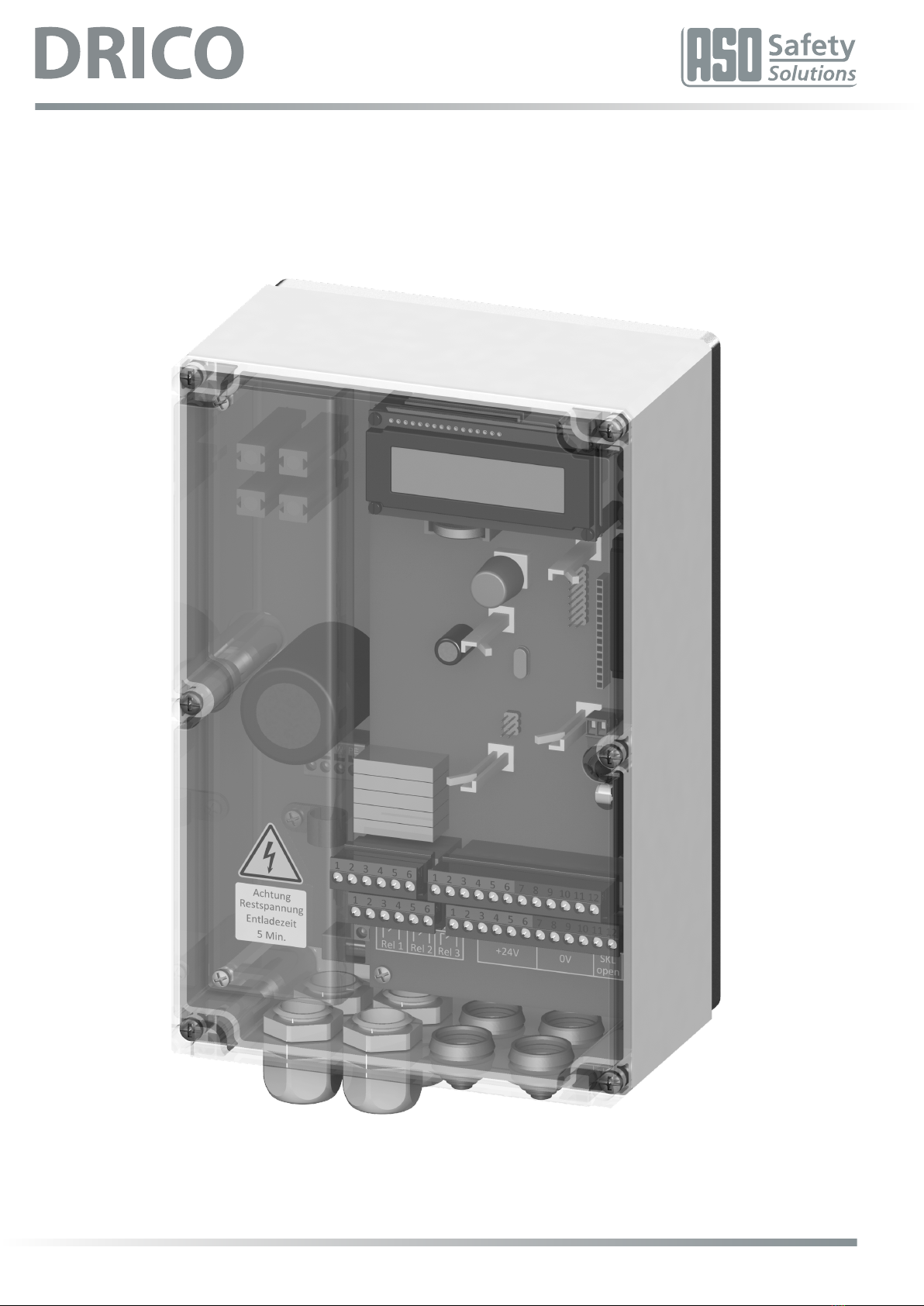
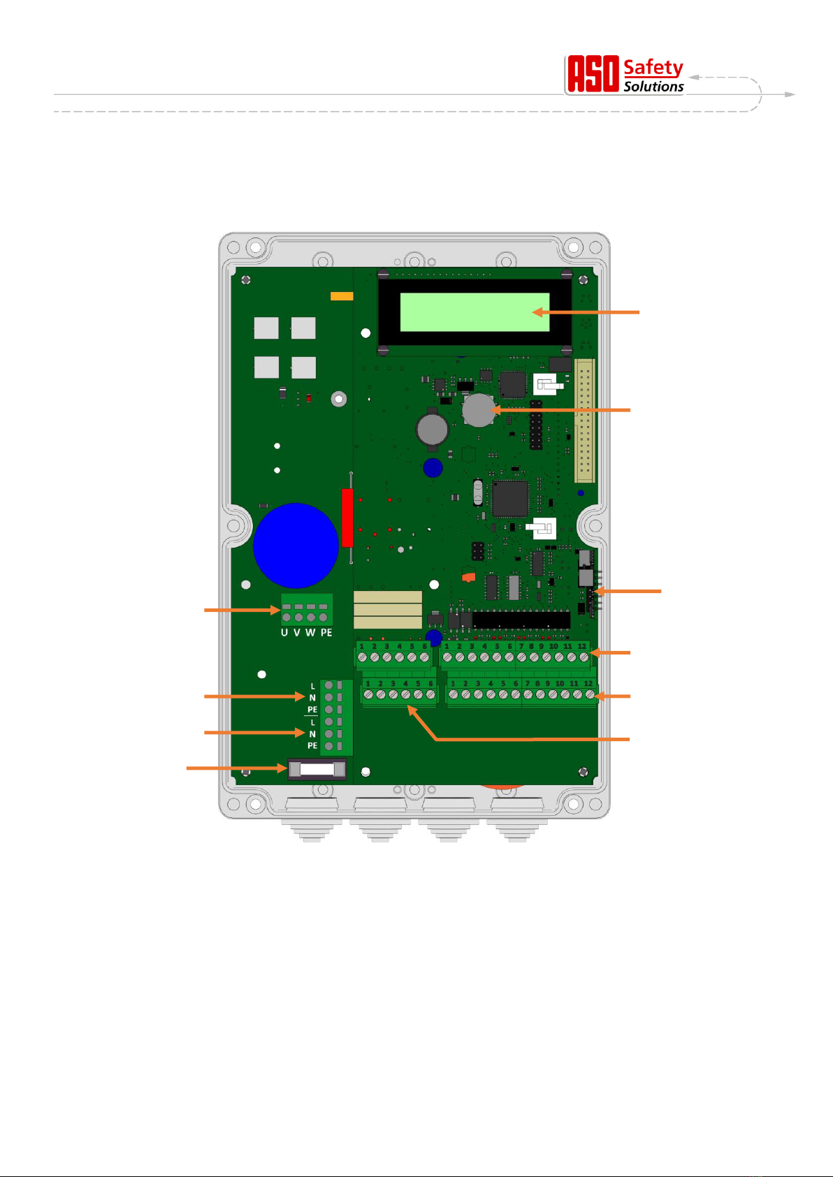
3.3 General view of the control system.................................................................. 9
3.4 Operating modes: Function and operation......................................................10
3.4.1 Deadman operation ...................................................................................................... 10
3.4.2 Automatic operation...................................................................................................... 10
3.4.3 Automatic change of the operating modes ................................................................... 11
3.5 Connectable auxiliary equipment....................................................................11
4Installation............................................................................................ 12
4.1 Control system assembly ...............................................................................12
4.2 Electrical connection.......................................................................................13
4.2.1 Power supply and drive motor connection.................................................................... 13
4.2.2 Instructions for suitable EMC installation...................................................................... 14
4.2.3 Supply for external consumers with 230 V AC ............................................................... 14
4.3 Input and output wiring ...................................................................................15
4.3.1 Power supply for external devices with 24 V DC............................................................ 15
4.3.2 Connection of the control devices and end switches ................................................... 15
4.3.3 Immobile safety contact edges ..................................................................................... 16
4.3.4 System connection INDUS ........................................................................................... 16
4.3.5 Light barrier connection ................................................................................................ 17
4.3.6 Overview of input installation plan ................................................................................ 18
4.4 Relay output wiring.........................................................................................18
4.4.1 Relay outputs with 24 VDC or with 230 VAC ................................................................... 19
5Operating elements and displays ......................................................... 20
5.1 Rotary and selection switch............................................................................20
5.2 LCD display....................................................................................................20
5.2.1 Depiction of operating modes ....................................................................................... 20
5.2.2 LCD sensor depiction ................................................................................................... 21
5.2.3 Error / event presentation ............................................................................................. 21
5.3 Information on menu display...........................................................................22
5.3.1 Menu system selection ................................................................................................. 23
5.4 Menu structure and displayed texts ................................................................23
6Parameter settings ............................................................................... 25
6.1 General instructions on parameterization .......................................................25
6.1.1 Navigating in menu ....................................................................................................... 25
6.2 Setting up the gate .........................................................................................26
6.2.1 Installation of the command keys for deadman operation............................................ 26
6.2.2 Change drive‘s direction of rotation .............................................................................. 27
6.2.3 Parameterize immobile safety contact edges............................................................... 27
6.2.4 Parameterize accompanying safety contact edges ...................................................... 27
6.2.5 Installation of the gate‘s end switches .......................................................................... 27
6.2.6 Programming the gate‘s runtime between the end positions ....................................... 28
6.3 Additional function parameters .......................................................................28

DRICO slife FU 12 Operating Manual
_______________________________________________________________________________________________________________________________________
DIN EN ISO 9001 status: 31.03.2017 / Rev. 01 page 4 of 48
6.3.1 Setting the language..................................................................................................... 28
6.3.2 Changing the operating mode: Deadman / automatic operation.................................. 29
6.3.3 STOP operating element .............................................................................................. 29
6.3.4 OPEN operating element.............................................................................................. 29
6.3.5 Selecting the operating functions on inputs In3 and In4............................................... 29
6.3.6 CLOSE operating element............................................................................................ 30
6.3.7 Set up partial OPEN function (pedestrian passage)..................................................... 30
6.3.8 Operating element switch impulse button (toggle) ....................................................... 31
6.3.9 Setting up light barrier................................................................................................... 31
6.3.10 Connecting a blinking light............................................................................................ 32
6.3.11 Setting up lighting (courtyard light) ............................................................................... 32
6.3.12 Connecting a gate status display.................................................................................. 32
6.3.13 Additional electrical brake............................................................................................. 33
6.3.14 Parameterizing a maintenance cycle counter............................................................... 33
6.3.15 Parameterizing a maintenance interval ........................................................................ 33
6.3.16 Parameterize maintenance requirement for relay output ............................................. 34
6.3.17 Parameterize maintenance requirement for blinking light ............................................ 34
6.3.18 Resetting the maintenance requirement....................................................................... 34
6.3.19 Resetting all parameter settings ................................................................................... 35
6.3.20 Setting the boost value ................................................................................................. 35
6.4 Automatic gate movement timing....................................................................35
6.4.1 Configure automatic closing (hold-open time).............................................................. 35
6.4.2 Time for closing from the PartialOPEN position ........................................................... 36
6.4.3 Time for closing the gate from intermediary positions.................................................. 36
6.5 Support for diagnose ......................................................................................36
6.5.1 Version display ............................................................................................................. 36
6.5.2 Active movement commands in switch on process ...................................................... 37
6.5.3 Gate status.................................................................................................................... 37
6.5.4 Sensor status................................................................................................................ 38
6.5.5 Temperature of power electronics ................................................................................ 38
6.5.6 Integrated logging system............................................................................................. 38
6.6 Parameters for reference and error numbers..................................................39
7Maintenance instructions...................................................................... 42
8Taking out of service and disposal ....................................................... 42
9Technical data ...................................................................................... 43
9.1 DRICO slife 150 FU 12...................................................................................43
9.2 DRICO slife 270 FU 12.1................................................................................44
10 Hersteller- / Konformitätserklärung....................................................... 45
10.1 DRICO slife 150 FU 12...................................................................................45
10.2 DRICO slife 270 FU 12.1................................................................................46

DRICO slife FU 12 Operating Manual
_______________________________________________________________________________________________________________________________________
DIN EN ISO 9001 status: 31.03.2017 / Rev. 01 page 5 of 48
1 General information
All previous versions lose their validity with this version. The information in this document can be
changed without previous notification.
This operating manual is specifically intended for the technical fitter of the gate control
DRICO slife FU 12.
The start-up of the control system may only be done by electricians with recognized training who
are familiar with the safety standards of electrical drive and automation technology.
The safety instructions must be adhered to unconditionally!
1.1 Symbol explanation
Attention!
The following safety instructions must be observed unconditionally to prevent personal
injuries.
Warning!
The following safety instructions must be observed unconditionally to prevent property
damage.
Information
Additional information or a reference to other documentation is provided here.
1.2 Overview of revisions
The schedule describes the revisions conducted on this document, the particular reason for the
revision and the revision date.
Revision
Date
Description
00
18.11.2016
further development of FU10 control wit new Controllern
01
31.03.2017
Content of control version 270 added

DRICO slife FU 12 Operating Manual
_______________________________________________________________________________________________________________________________________
DIN EN ISO 9001 status: 31.03.2017 / Rev. 01 page 6 of 48
1.3 Terminology, definitions and abbreviations
AC Alternating Current
CRC16 16 Bit Cyclic Redundancy Check
DC Direct Current
DIN Deutsches Institut für Normung
EEPROM Electrical Eraseable Programmable Read Only Memory
EMC Electromagnetic compatibility
EN European standard
FI Residual current circuit breaker
FU Frequency converter
GND Ground potential
HW Hardware
IP Protection type against foreign objects and water (intrusion protection)
ISK Inductive cable transfer system from the company ASO that replaces
the towing cable for the transmission of the travelling safety contact edge
ISO Internationale Organisation für Normung (International Organisation for
Standardization)
LCD Liquid CrystalDisplay
RAM Random Access Memory
ROM Read Only Memory
SCE Safety Contact Edge
SW Software
TÜV Technischer Überwachungsverein
VCC Voltage of Common Collector
1.4 List of figures
Figure 1: Overall view of the control unit....................................................................................... 9
Figure 2: Mechanical dimensions................................................................................................ 12
Figure 3: Power supply and motor connection............................................................................ 13
Figure 4: Connection of external devices.................................................................................... 15
Figure 5: Connection for tested through-beam light barrier ........................................................ 17
Figure 6: Connection for reflected-light barrier ........................................................................... 17
Figure 7: Example installation with end switches, light barrier and safety contact edges .......... 18
Figure 8: Connection of relay with 24 VDC................................................................................... 19
Figure 9: Connection relay with 230 V ........................................................................................ 19

DRICO slife FU 12 Operating Manual
_______________________________________________________________________________________________________________________________________
DIN EN ISO 9001 status: 31.03.2017 / Rev. 01 page 7 of 48
2 Safety instructions
•Carefully read the operating instructions before putting then the gate control system
into operation.
•The installation and start-up of the control system may only be conducted by
specialised personnel that are familiar with the operating instructions and the
applicable regulations on job safety and accident prevention. The instructions in these
operating instructions must be followed and adhered to unconditionally.
•The operating instructions must always be available at the control system‘s site of operation.
They must be thoroughly read and applied by every person who is tasked with the operation,
maintenance and repair of the control system.
•The operators of the gate system or their representatives must be trained in the operation of
the system after the system is started.
•Electrical work may only be completed by electricians.
•Safety regulations for electrical engineering and from professional associations must be
followed.
•The manufacturer and user of the system/machine on which the control system is used are
responsible for coordinating and adhering to all applicable safety regulations and rules under
their own responsibility.
•The instructions in these operating instructions must be followed to guarantee function and
safety. Bodily injuries or property damage may arise as a result of disregard of the warning
instructions. The manufacturer is not liable for damages caused as a result of non-observance
of the instructions.
•The control system does not contain any components that the user must service. Any warranty
or liability on the part of the manufacturer is forfeited in the event of unauthorized
modifications or repairs to the control system.
•The drive system must absolutely be removed from the power supply prior to wiring work. It
must be ensured that the power supply remains interrupted during wiring work.
•All impulse transmitters and control devices for the gate must be mounted within view of the
gate and at a safe distance from the gate‘s moveable parts. A minimum mounting height of 1.5
meters must be adhered to.
•It must be ensured that children cannot play with the gate control.
•Before the gate is moved it must be ensured that there are no people or objects in the gate‘s
hazard area.
•All existing emergency command devices must be checked before starting the system.
•Reaching into a running gate or moving parts is never permitted.
•Possible crushing and shearing points on the gate system must be taken into consideration
and if necessary protected.
•The control system guarantees functional safety, but not the safety of the entire system. Thus,
a safety review of the entire system in accordance with DIN EN 13241-1 „doors and gates -
product standard“ is necessary prior to use of the control system.
•The system must be checked for correct function in suitable intervals by qualified persons for
the standard-conform design of the safety system in accordance with the standard DIN EN
12453 „Safety in use of power operated doors and gates“. The check must be documented in
a way that allows it to be traced at any time.
The gate control system is a frequency converter. There may still be dangerous
voltages after shutdown due to loaded capacities. Thus, a waiting time of 5 minutes for
the discharging of the capacities must be adhered to.
There is danger to life with respect to live working on the frequency converter circuit board!
Only type B AC/DC sensitive residual current circuit breakers may be used if the control
system is protected with a residual current circuit breaker.

DRICO slife FU 12 Operating Manual
_______________________________________________________________________________________________________________________________________
DIN EN ISO 9001 status: 31.03.2017 / Rev. 01 page 8 of 48
3 Function description and connections
The present document is a description of the electrical gate control system DRICO slife FU12 of
ASO. It contains the installation, operation, maintenance, repair, shutdown and disposal of the
control system.
DRICO slife is an electronic control unit with safety functionality. It is used as a control system for
the operation of gates in the industrial environment. It contains a frequency converter and can
operate a three-phase motor with up to 0.75 kW electrical power on a one-phase network. The
frequency converter makes gate soft-start and braking possible. The maximum frequency
transmitted by the converter is limited to a maximum of 75 Hz.
3.1 Requirements
The control system is only fully functional in the ready-to-use gate system. Additional external
components may also be required, for example:
- Drive (electric motor and transmission)
- Command input devices (switch/button)
- Signal devices (blinking lights/horns)
- Sensor elements (Safety edges/light barriers)
These are not included in the control system‘s scope of delivery.
3.2 Technical characteristics
The DRICO slife FU12 has the following characteristics:
Auto-configuration and comprehensive default settings for standard gate systems
Comprehensive parameterization system
2 inputs for the deadman (Hold to run) operator buttons OPEN and CLOSE
inputs for the automatic control device STOP, OPEN, PartialOPEN and TOGGLE switching
impulse (OPEN, STOP, CLOSE, STOP, ...)
2 inputs for the gate end switches OPEN and CLOSE
output relays (normal open contacts) for blinking light, gate position OPEN and position
CLOSED, Motor brake, maintenance requirement
INDUS and SENTIR edge inputs can be connected via screw terminals, for the evaluation of
the moving and fixed safety contact edges
Separate input for light barrier
Operation and configuration via rotary and selection switch
7-segment display for status reports
LC display for diagnostic display and parametrization via menu navigation
Optional radio receiver for hand-held radio transmitters for remote control of the gate

DRICO slife FU 12 Operating Manual
_______________________________________________________________________________________________________________________________________
DIN EN ISO 9001 status: 31.03.2017 / Rev. 01 page 9 of 48
3.3 General view of the control system
An overview of the relevant parts is provided in the general view shown of the control system; they
are also referred to in the text of these operating instruction.
Figure 1: Overall view of the control unit
Designations:
1 LC text display
2 Rotary and selection switch to select display and for settings
3 Electrical evaluation device for the accompanying safety contact edges:
INDUS onboard 70-757
4 Connections for the inputs for the control device, light barrier and INDUS core
5 Connection for the power supply of the external 24 VDC devices and operating elements
as well as for the immobile safety contact edges
6 Connections for the Rel1 to Rel3 relay outputs
7 Motor connection
1
2
3
4
5
6
7
8
9
10

DRICO slife FU 12 Operating Manual
_______________________________________________________________________________________________________________________________________
DIN EN ISO 9001 status: 31.03.2017 / Rev. 01 page 10 of 48
8 230 VAC / 50 Hz Power supply connection
9 Connection for additional 230 VAC / 50 Hz loads
10 Fuse for the external 230 V loads (6,3 A) on terminal 6
3.4 Operating modes: Function and operation
The controller software is subdivided into individual function modules and is depicted for the user
in two possible operating modes (deadman operation and automatic operation).
3.4.1 Deadman operation
The gate control system can be used in deadman (Hold To Run) operation with limited comfort. In
deadman operation the gate can only be moved with the OPEN and CLOSE buttons specifically
connected to inputs ,In8‘ and ,In7‘. The gate does not require any safety contact strips for this
operation. The gate is only in operation for as long as the open or close button is pressed.
Deadman operation is only permitted, if the user has full visual contact with the gate system.
Even in deadman operation mode a STOP button is to be provided for in addition to the OPEN
and CLOSE buttons. If this button is not to be connected, the relevant input must be connected by
a wire bridge with +24 volts.
The control system also automatically switches out of automatic operation to this operating mode
if the safety devices on the gate do no longer permit automatic operation (e.g. defective safety
edges / light barrier). In this case the operator must also keep the command button (OPEN [In8] or
CLOSE [In7]) continuously pressed. The gate movement will only be initiated with a delay of 2
seconds. This is a safety feature and serves to signal the operator the transition from automatic
mode to deadman operating mode.
3.4.2 Automatic operation
The control system is normally operated in this automatic mode when safety is completely
established. All of the control system‘s functions are only available to the user in automatic
operation. Here, the gate‘s complete safety is guaranteed by the activated safety devices.
In automatic operation a gate movement can be initiated by:
deadman button OPEN or CLOSE
Control device (OPEN or PartialOPEN)
Impulse button with TOGGLE function (OPEN, STOP, CLOSE, STOP)
Commands via radio remote control
Every command results in the execution of the complete, selected action (open gate, close gate,
etc.). Every action is immediately ended with a stop command or a signal from the safety devices.
Activation of the safety contact edges results in an immediate, complete reversal of the gate. An
interruption of the light barrier during the closing operation also results in the gate opening.
A movement command for the opposite direction of the current movement gently brakes the gate
and then makes it move in the opposite direction.

DRICO slife FU 12 Operating Manual
_______________________________________________________________________________________________________________________________________
DIN EN ISO 9001 status: 31.03.2017 / Rev. 01 page 11 of 48
Automatic operation with incomplete setup:
If the gate has not yet been completely set up or if the control system‘s reference run has not
yet been concluded, the control system run in a special safety mode (example: The gate‘s end
positions have not yet been detected in the reference run).
The gate then only moves at a slower speed. The automatic speed is not used until after the test
run with slow speed.
Even if the drive unit was electrically voltage-free, the gate only moves at slow speed at first until
an end position has been reached.
3.4.3 Automatic change of the operating modes
In the event of the failure of electronic safety devices on the gate (e.g. defective safety edge or
light barrier), the control system can automatically switch from automatic operation to deadman
operation. This automatic change is only made for an initiated motor movement and only in the
event of activation of the button intended for deadman operation. Subsequently, the control
system reassumes automatic operation; however, it can switch back to deadman operation in the
event of a renewed or persistent defect during the next run.
A change between the operating modes is possible in the following directions:
Automatic operation deadman operation
Deadman operation automatic operation (if safety has been re-established)
3.5 Connectable auxiliary equipment
The gate control system can be operated with one or more of the following components:
Safety contact edges Safety contact edges with an 8.2-kOhm load resistance for the
open and close direction can be connected directly over clamping
units (Image 1: General view no. 10).
ISK-System The control unit already contains the control and evaluation logic for
the inductive safety system ISK for the monitoring of travelling
safety contact edges (8.2 kOhm).
The INDUS onboard 70-757 is attached to the control system for
this purpose (figure 1: General view No.12. On a terminal (figure1
General view No.11) you can directly connect the immobile core
SPK 55.
Light barriers One-way light barriers or reflected-light barriers can be connected
on a separate input (figure 1: General view No. 11).

DRICO slife FU 12 Operating Manual
_______________________________________________________________________________________________________________________________________
DIN EN ISO 9001 status: 31.03.2017 / Rev. 01 page 12 of 48
4 Installation
This chapter deals with the start-up of the DRICO slife.
4.1 Control system assembly
Warning!
The control system must be checked for any transport or other damages prior to
assembly!
Touching electronic parts, in particular the processor circuit parts, must be avoided.
Electronic parts can be damaged or destroyed by electrostatic discharges.
The system must be kept at zero-potential during the assembly of the control system.
The control system must be assembled in a way that is mechanically free of distortion.
Unused cable entry points must be replaced with sealing plugs in order to guarantee the
housing‘s safety class.
The cables may not be exposed to any mechanical tensile loading.
If the control system is assembled on a conductive surface, this surface must be
connected to PE with an adequate ground wire connection. The control system‘s cooling
element does not constitute such a ground wire connection on its own.
The control system is mounted using four cylinder head screws with a diameter of 4 mm.
The control system is intended for vertical mounting.
Figure 2: Mechanical dimensions
Note: The control system‘s cooling element warms up during operation. Thus, adequate thermal
coupling of the cooling element must be taken into consideration. A form-fitting connection of the
cooling element with a heat-dissipating metal surface is ideal. The mounting of the control system on a
flammable surface (e.g. wood) is not permitted.
With regard to non-heat-dissipating surfaces, the control system must be mounted with clearance with
distance bolts. Air space of at least 10 cm must be planned above and below the control system for
convection. Insufficient heat dissipation can negatively impact the control system‘s function.
In the event of continuous operation, the cooling element can reach up to 65°C. The frequency
converter turns itself off at higher temperatures.
Fixing bores

DRICO slife FU 12 Operating Manual
_______________________________________________________________________________________________________________________________________
DIN EN ISO 9001 status: 31.03.2017 / Rev. 01 page 13 of 48
4.2 Electrical connection
Attention!
For safety reasons, electrical installation must always be completed by an authorized
electrician.
Work on the control system is only permitted with all-pole disconnected power. A power cut-off
switch or the use of a plug must be planed for all-pole disconnect. The power cut-off switch or the
power plug must be easily accessible.
The points listed in the Safety Instructions section (chapter: 2) must be observed.
The parallel routing of signal and energy lines should be avoided to the greatest possible extent.
All lines should be assessed according to their power consumption.
The graduated nipples used in the housing may only be opened wide enough that the protection
against water and foreign objects still corresponds to the IP class once the lines have been fed
through. Damaged cable feedthroughs must be replaced immediately with undamaged ones.
4.2.1 Power supply and drive motor connection
The DRICO slife is designed for a one-phase input voltage of 230 V AC and generates a rotating
field of 3 x 230 V AC. The supply voltage is connected to the lower power board via the terminals
labelled with „L“, „N“, and „PE“ (figure 3 No. 5).
The three-phase motor occupies the terminals „U“, „V“, „W“, and „PE“ (figure 3 No. 4). When
connecting the motor itself, the motor manufacturer‘s connection plans must be observed.
Absolutely ensure the correct connection of the protective earth conductor and the motor
connection cable.
DRICO slife FU 150 DRICO slife FU 270
Figure 3: Power supply and motor connection
1 - Three-phase motor connection
2 - Voltage supply 230 V
3 - External 230 V consumers
4 - Microfuse for external consumers (6.3 A delay)
5 - brake chopper
1
2
3
4
5

DRICO slife FU 12 Operating Manual
_______________________________________________________________________________________________________________________________________
DIN EN ISO 9001 status: 31.03.2017 / Rev. 01 page 14 of 48
When starting the gate system, the motor‘s direction of rotation must be taken into consideration
so that the gate also moves in the desired direction when the OPEN button is activated. If
necessary, the motor connections „V“ and „W“ must be exchanged or the motor‘s direction of
rotation must be changed per software via the configuration in the menu.
4.2.2 Instructions for suitable EMC installation
Attention!
Damage to other devices in the immediate vicinity of the control device may occur in the event
of unsuitable EMC installation.
The DRICO slife is a frequency converter control system. Frequency converters are devices that can
generate electromagnetic interferences in your surroundings due to their circuitry.
Thus, only a shielded line can be used as a motor line. The shield must be connected to the motor via
an EMC screw connection and in the control system to the intended PE clamp.
4.2.3 Supply for external consumers with 230 V AC
External appliances for the control system that work with 230 V AC power supply can be connected
via the secured voltage output with the terminal designation „L“ on the control system‘s power
board (figure 3 No. 6.) The maximum load, determined by the integrated safety fuse (figure 3 No.
7) must be observed in the process.

DRICO slife FU 12 Operating Manual
_______________________________________________________________________________________________________________________________________
DIN EN ISO 9001 status: 31.03.2017 / Rev. 01 page 15 of 48
4.3 Input and output wiring
There are two terminal blocks for the connection of external devices arranged next to one another
on the control system. The left block is intended for relay outputs (figure 1: General view No.: 9),
while control devices and sensors can be connected on the right block (figure 1: General view No.:
10 and 11). The terminal designation is printed on the board below the terminals.
Said terminals are also shown individually in figure 4 below for better identification.
Figure 4: Connection of external devices
4.3.1 Power supply for external devices with 24 V DC
An isolated and voltage-stabilized 24 VDC power supply that can supply a maximum 500 mA current is provided in
the control system for the power supply for external devices, control devices and sensors. This supply voltage is
protected on the circuit board with a fuse with automatic reset. The 24 volts are available on the lower terminal
strip (Image 4 No. 10.1) on the left contact points No. 10.2) with the designation „0V“.
Image No.
Terminal No.
Designation
Function
10.1
1 to 4
+24 V
+24 Volt DC power supply
10.2
5 to 8
0 V
Ground potential for external 24 V consumers
4.3.2 Connection of the control devices and end switches
The inputs for the control devices and control system are marked on the upper terminal strip with „In1“ to
„In8“ (figure 4 No. 11.3) and assigned the following functions:

DRICO slife FU 12 Operating Manual
_______________________________________________________________________________________________________________________________________
DIN EN ISO 9001 status: 31.03.2017 / Rev. 01 page 16 of 48
Image No.
Term. No.
Design.
Input function
11.3
3
In8
Deadman button OPEN (e.g. key switch button on gate)
11.3
4
In7
Deadman button CLOSE (e.g. key switch button on gate)
11.3
5
In6
STOP button (normally closed contact)
11.3
6
In5
OPEN impulse
11.3
7
In4
PartialOPEN impulse (pedestrian passage)
11.3
8
In3
TOGGLE switching impulse (OPEN/STOP/CLOSE/STOP)
11.3
9
In2
End switch for OPEN position (normally closed contact)
11.3
10
In1
End switch for CLOSE position (normally closed contact)
Buttons with normal open contact are connected as control devices for the open, close and
switching impulse functions (toggle). For the functions OPEN [In5] or PartialOPEN [In4], a switch
with a static make contact is also possible (e.g. timer) to keep the gate open.
Only control devices with a normally closed contact are used for the STOP function. Multiple
openers can be switched in series one after the other in the form of a stop chain.
The end switches for the gate‘s OPEN and CLOSE position are also normally closed contacts.
The two colored input functions represent the version 1. In 6.3.5 is described how different
functions can be allocated to these two inputs.
Both of the input functions shown in grey in the table constitute variant 1. Section 6.3.5 contains a
description of how both of these inputs can also be assigned other functions.
In order to fulfill the special requirements for deadman operation, the „In7“ and „In8“ inputs may
only be allocated to buttons the operation of which always guarantees complete view of the gate
system and risk-free use.
4.3.3 Immobile safety contact edges
The immobile safety contact edges (8.2 kOhm) for protection of the gate can be directly connected
to the pluggable terminals on the bottom right of the input terminal block. Terminals 9 and 10 are
marked with SKL open (figure 4 no. 10.3) on the conductor board. Here, the edge can be
connected in the gate‘s OPEN direction.
11 and 12--which are marked with „SKL close“--are for the connection of the safety contact edge
in the CLOSE direction (figure 4 No. 10.4).
Image no.
Terminal no.
Designation
Input function
10.3.
9,10
SKL open
Immobile safety contact edges OPEN (open direction)
10.4
11,12
SKL close
Immobile safety contact edges CLOSE (close direction)
The evaluation of the signals of the contact strips is effected in the control unit’s software.
4.3.4 System connection INDUS
The evaluation of the inductive cable transfer system INDUS for the accompanying safety contact
edges on the gate (8.2 kOhm) is already integrated in the control system - INDUS onboard 70-757
(figure 1: General view No. 12). The immobile core SPK55 can be directly connected to both of the
right terminals no. 11 and 12 up on the input terminal block with the designation ISK (figure 4 no.
11.4).
The signals for the accompanying safety contact strips are subsesquently safety-evaluated in the
control system.

DRICO slife FU 12 Operating Manual
_______________________________________________________________________________________________________________________________________
DIN EN ISO 9001 status: 31.03.2017 / Rev. 01 page 17 of 48
Figure No.
Terminal No.
Designation
Input function
11.4
11, 12
ISK
ISK input (immobile core)
4.3.5 Light barrier connection
Through-beam light barriers as well as reflected-light barriers that work with 24 VDC operating voltage can be
directly connected to the control system.
The light barrier‘s input signal is connected to terminal No. 2 with the designation „LB in“ (figure 4 no. 11.2).
Figure no.
Terminal no.
Designation
Input function
11.2
11, 12
LB in
Light barrier input signal
The upper left clamp no. 1 with the designation „24V ¯|_|¯“ (figure 4 no. 11.1) is a 24 volt supply
that is briefly shutdown every 5 minutes for testing purposes. A light barrier‘s transmitter, for
example, can be connected to this voltage supply. The light barrier‘s input signal function is
checked during the brief shutdown phase.
The different connection between a through-beam light barrier tested by blanking the transmitter
and an untested reflected-light barrier is shown in an example in the following two images:
Figure 5: Connection for tested through-beam light barrier
Figure 6: Connection for reflected-light barrier

DRICO slife FU 12 Operating Manual
_______________________________________________________________________________________________________________________________________
DIN EN ISO 9001 status: 31.03.2017 / Rev. 01 page 18 of 48
4.3.6 Overview of input installation plan
The DRICO slife is configured for operation with end switches. The connection for the control
devices and sensors to the inputs is shown in a typical configuration in the following drawing:
Figure 7: Example installation with end switches, light barrier and safety contact edges
4.4 Relay output wiring
The DRICO slife provides three relays with normal open contact for signaling and lighting
purposes. The switching contacts are potential-free and can switch ohmic loads of maximum
250 W. The relays are preset with the following functions:
Figure no.
Terminal no.
Design.
Output function
9.1
1, 2
Rel1
Flashing light or beacon light
9.2
3, 4
Rel2
OPEN state of the gate
9.3
5, 6
Rel3
CLOSED state of the gate
The output of Rel1 (figure 4, no. 9.1) with the warning light function is permanently switched on
with the beginning of the pre-warning time and during the gate movement. The blinking function
has to be effected by the connected lamp.

DRICO slife FU 12 Operating Manual
_______________________________________________________________________________________________________________________________________
DIN EN ISO 9001 status: 31.03.2017 / Rev. 01 page 19 of 48
The service engineer can configure the following functions onto the relays Rel2 (figure 4 no. 9.2)
and Rel3 (figure 4 no. 9.3):
Lighting (courtyard light) with shutdown delay after the end of the gate movement
Maintenance signal (maintenance required)
Additional electrical brake
Warning: When assigning the functions to the individual relays it is necessary to ensure that
the outputs are not doubly configured. An output that has already been configured must first
be released from its previous function before it can be assigned another function.
4.4.1 Relay outputs with 24 VDC or with 230 VAC
Control lamps with 24-volt supply voltage can be connected as shown in the following figure 8.
Figure 8: Connection of relay with 24 VDC
Figure 9: Connection relay with 230 V
Warning:
The control system‘s maximum current capacity of 500 mA must be taken into consideration
when wiring the external 24 V supply.
There is a 230 V output for external consumers on the control system‘s power board (figure 3 No. 6)
that is protected with a glass tube fuse (6.3 A delay) (figure 3 No.7). 230 V consumers can also be
switched via this supply output and the relays. The connection of a corresponding control lamp or
blinking lamp can thus be established as shown in figure 9.
Warning:
The supply output‘s maximum current capacity must be taken into consideration during wiring.
Furthermore, the maximum load of 250 W must be observed for each individual relay.
The fuse (6.3 A delay) may only be replaced with a fuse with the same connection value.
Caution:
The relay outputs are separated from the safety extra-low voltage in the control system in a
way that conforms to standards. However, the individual relay connections amongst
themselves do not fulfil this requirement.
Therefore a mixed operation of the connection on the 230 VAC and 24 VDC relays is not
permissible (either all 230 VAC relays or all 24 VDC relays).

DRICO slife FU 12 Operating Manual
_______________________________________________________________________________________________________________________________________
DIN EN ISO 9001 status: 31.03.2017 / Rev. 01 page 20 of 48
5 Operating elements and displays
Entries in the installed software of the control system are made via a modern one-button operating
element, the rotary and selection switch. Visual responses from the program to the operator are
made via the liquid crystal display (LCD) and the 7-segment display (LED).
5.1 Rotary and selection switch
The control system display can be influenced using the rotary and selection switch (figure 1:
General view No.: 2). The control system‘s parameterization can also be activated via said rotary
and selection switch with the help of the integrated menu system. This operating button has two
functions. By rotating, the size of a displayed value can be changed: to the right (clockwise)
increases; to the left (counter-clockwise) reduces. It is also possible to move backward and
forward in a displayed table or a memory area by rotating.
By pressing the button down another mode is selected, or a display or selection (menu) is quit.
5.2 LCD display
An LC display with 2 rows that each have 16 characters is intended in order to be able to display
comprehensive information from the control system (figure 1: General view No.: 3). For example,
the respec¬tive active operating mode or the motor movement status (open, close) of the control
system is shown on the display in plain text.
ASO DS150 FU
Automatic Mode
The display‘s background lighting is active as long as entries are made via the rotary and selection
switch. The lighting goes out 20 seconds after the last actuation. However, it can be switched back
on at any time by rotating the selection switch.
Information:
The display‘s lighting blinks for a few seconds after the control system is switched on or after
a software reset. This signals the program‘s start process.
5.2.1 Depiction of operating modes
The following displays are possible in the LCD display‘s depiction of the operating modes:
Display
Meaning
ATC150 Pe:x.xxr
Start display of the peripheral controller
(during synchronization with the motor controller)
ASO DS150 FU
Automatic Mode
Automatic operating mode; the motor is not running
Automatic Mode
Opening
Automatic operation; Open gate active
Automatic Mode
Closing
Automatic operation; Close gate active
Automatic Mode
Stop Immediately
Automatic operation; STOP active
Automatic Mode
Closing: XX
Automatic operation; gate closes automatically after expir. of xx
seconds
ASO DS150 FU
Hold to Run Mode
Deadman operating mode idle state
This manual suits for next models
2
Table of contents