ASP Intelligent RS-485 User manual

Intelligent
RS-485 & RS-422
Adaptors
The Intelligent RS-485 and RS-422 Adaptors
are designed and built in Australia by:
ASP Microcomputers
14 Business Park Drive,
Notting Hill, Victoria, 3168
Australia
Telephone: (03) 9578-7600
FAX: (03) 9578-7727
World Wide Web: http://www.asp.com.au
(ASP Microcomputers is a division of Grayline Holdings Pty. Ltd,. A.C.N. 004 940 729)
Manual revised: Nov 19th,2020 Copyright © 1999-2020 by ASP Microcomputers


Contents
The Intelligent RS-485 and RS-422 Adaptors........................................1
Front Panel Indicators.............................................................................1
RS-485 and RS-422 Cabling ..................................................................2
Cable Termination..................................................................................3
Power Supplies.......................................................................................4
Network Expansion ................................................................................5
The Main Cabling Points Again!............................................................5
Technical Information ............................................................................6
RS-232 Connector ..................................................................................6
RS-485 Connector ..................................................................................6
RS-422 Connector ..................................................................................7
RJ-45 Connector.....................................................................................7
Jumper Options.......................................................................................8
Warranty.................................................................................................9
Year 2000 Statement ..............................................................................9
EMC Statement ......................................................................................9


Intelligent RS-485 and RS-422 Adaptors
1
The Intelligent RS-485 and RS-422 Adaptors
ASP’s Intelligent RS-485 and RS-422 Adaptors are designed to connect
between a PC’s RS-232 serial port and ASP’s ZipNet/ClassNet (RS-
485) and ASPNet (RS-422) Terminals.
RS-485, as used by ASP’s ZipNet and ClassNet Terminals, is a half-
duplex communications standard, with transmission and reception
taking place alternately over a single pair of wires. The ZipNet and
ClassNet Terminals use a master/slave protocol to communicate with
the PC, with the PC being the master. The Intelligent RS-485 adaptor
normally operates in receive mode, but as soon as it detects data from
the PC, it switches to transmit mode, then immediately back to receive
mode as soon as the PC stops sending data. The ZipNet and ClassNet
Terminals operate at 9600 baud.
RS-422, as used by ASP’s ASPNet Terminals, is a full-duplex
communications standard, with a separate pair of wires for transmission
and reception. ASPNet Terminals use a master/slave protocol to
communicate with to the PC, with the PC being the master. Because
RS-422 uses a separate pair of wires for data in each direction, the
Intelligent RS-422 adaptor is always able to both send and receive
mode – there is no need to turn the transmitter on and off. A network
of ASPNet Terminals normally operates at 38,400 baud, but when some
ancillary devices (such as ASPNet Access Controllers) are used, the
network must operate as 9600 baud.
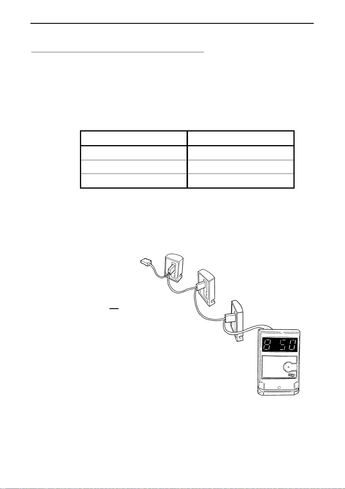
RS-485 and RS-422 networks are normally wired as a daisy-chain, with
the network cabling running from one unit to the next in a single run of
cable.
Because the Intelligent RS-485 and RS-422 Adaptors are really just
different versions of the same device, they are both described in the
same manual.
Front Panel Indicators
The front panel of the Intelligent RS-485 and RS-422 Adaptors contain
three indicators. These are, from left to right:
• A red power indicator, lit when the adaptor is connect to power.
• A green Transmit Enable indicator, which lights up in RS-485 mode
to indicate that the transmitter is enabled.
• A dual-colour Rx/Tx indicator, which lights up red when data is
being transmitted, green when data is being received, and is unlit
when there is no data.

Intelligent RS-485 and RS-422 Adaptors
2
RS-485 and RS-422 Cabling
RS-422 and RS-485 are specifications for multi-drop serial digital
communications over long distances with high noise immunity.
In ASP products, RS-422 is a four-wire connection (with one twisted-
pair used for transmission and one twisted-pair used for reception), and
RS-485 is a two-wire connection (with transmission and reception
taking place alternately over a single twisted-pair).
ASP RS-422 products ASP RS-485 products
ASPNet Terminals ClassNet Terminal
ASPNet Access Controller ZipNet Terminal
Networked Portable BCR WandNet
ASP RS-422 and RS-485 networks must be wired using a single run of
shielded twisted-pair cable, daisy chained to each unit. The cable must
be looped to each unit in one continuous run - there must be no "T" or
"Y" connections in the cable. Cable joins are acceptable only at the
actual connectors at each unit (see the diagram below).
Note that although
this diagram shows
ClassNet or ZipNet
units, the way the
cable is run is
applicable to all
ASP networked
units.
In a typical
installation, one
end of the cable is
connected to the
Intelligent RS-485
or RS-422
Adaptors at the
controlling computer (which plugs into one of the computer's serial
ports). The cable is then run to each networked unit in turn, with no
branches or junctions.

Intelligent RS-485 and RS-422 Adaptors
3
The cable's outer shield must be continuous from one end of the cable
to the other, and not connected to anything other than the ground pins at
the Intelligent RS-485 and RS-422 Adaptor and each networked unit.
It is vitally important that the twisted-pairs of the cable be used as pairs
- do not use one wire of one pair and another wire of another pair.
Unless you’re practiced in handling multi-pair cable, you’ll probably
find it easiest to identify the twisted-pairs if you strip the cable about 20
to 30cm back from the end.
Care must be taken with the routing of the cable when it is installed.
The ideal situation is for the network cable to be kept as far away from
other cabling (ie mains power, telephone, alarm, RF, etc) as possible.
Where possible, the network cable should cross other cables at a right-
angle.
ASP recommends the use of MCP-2S (for RS-485) or MCP-3S (for
RS–422) shielded low-voltage twisted-pair computer data cable. These
cables, which contain two or three twisted-pairs of wires respectively,
are available in 100 metre and 500 metre rolls from A.G. Garlands &
Co Pty Ltd in Melbourne (phone (03) 9543 6411, with offices in other
states). Other suppliers may have equivalent twisted-pair data cable.
Category 5 or Category 3 twisted pair cable is also suitable.
Although the Intelligent RS-485 and RS-422 Adaptors are normally
used at one end of the cable, there is no reason why the adaptors cannot
be installed at some point along the cable. This method of wiring may
be more convenient in some installations. Note, however, that the cable
must be terminated only at the ends.
Cable Termination
For proper operation, each end of each pair of wires in an RS-485 and
RS-422 network cable must be terminated with a 120 ohm ¼ watt
resistor.
The Intelligent RS-485 Adaptor is fitted with an internal terminating
resistor, enabled via a jumper. The Intelligent RS-422 adaptor is fitted
with an internal terminating resistor on the receive data line only, also
enabled via a jumper - remember that the RS-422 transmit line must
also be terminated. See page 8for jumper details.
Don’t forget that the far end of the cable also needs to be terminated!

Intelligent RS-485 and RS-422 Adaptors
4
Power Supplies
The Intelligent RS-485 and RS-422 Adaptors require 9 to 18 volts DC
at 100mA, normally supplied by a 9v DC 300mA plug pack power
supply, via a centre-positive 2.5mm DC connector. The adaptors are
protected from reverse polarity by a 1A series diode.
The Intelligent RS-485 and RS-422 Adaptors can be configured (via an
internal jumper) to supply unregulated DC voltage (from the plug pack
powering the adaptor) to the RS-485 and RS-422 connectors. The
maximum current that can be drawn in this way must be limited to
either 500mA, or 100mA less than the capacity of the plug pack,
whichever is the smaller. Note that this output is not fused or protected.
Using the recommended MCP-2S cable for RS-485 installations and
MCP-3S cable for RS-422 installations provides for a spare pair of
wires. In some installations, it will be possible to use this spare pair to
provide power over the cable to the networked units, either from the
Intelligent RS-485 and RS-422 Adaptors (see above), or from another
power supply.
The following points should be noted:
• The ASPNet Terminal and the Networked Portable BCR both
require 9 to 18v DC power. All other units will accept either 8 to
16v AC or 9 to 18v DC power.
• The voltage drop can be very high, especially if the cable run is long,
or a large number of units are being powered. You must ensure that
sufficient power reaches each unit.
• As a simple “rule of thumb”, each unit requires approximately
100mA of current.
• In anything other than a very small network, it will most likely be
necessary to use more than one power supply, each powering a
number of units on a segment of the cable.

Intelligent RS-485 and RS-422 Adaptors
5
Network Expansion
Provided the cabling is correctly installed and terminated, RS-422 and
RS-485 networks allow a maximum total cable length of 1200 metres,
and can support a maximum load of 31 units plus the RS-422 or RS-
485 adaptor per network. The easiest method of allowing more than 31
units is to split the network into multiple sections, and run each section
from its own adaptor on different serial ports on a single PC. Typical
PC’s have two serial ports, and multiple serial port expansion boards
are available that provide two, four or eight additional serial ports.
Remember that each section of the network can be up to 1200 metres
long, and can support up to 31 units.
Although we have had some users connect more than 31 units together
in a single network without experiencing any problems, we do not
recommend doing so.
The Main Cabling Points Again!
• The cable must be shielded twisted-pair computer data cable.
• The twisted pairs of wire in the cable must be used as pairs.
• The cable must be installed in one continuous run - no joins,
junctions, taps or “T” connections are allowed.
• The shield must be continuous, and connected to ground pins on the
adaptor and each unit.
• The cable must be terminated at each end.
Provided you follow these instructions, you should have no problems
running an RS-485 or RS-422 network up to the maximum of 1200
metres and 31 units.

Intelligent RS-485 and RS-422 Adaptors
6
Technical Information
This section of the manual details the pinouts of the Intelligent RS-485
and RS-422 Adaptors.
RS-232 Connector
The female DB-25 connector on the Intelligent RS-485 and RS-422
Adaptors is designed to plug straight into a DB-25 or DB-9 serial port
on your PC, using a standard PC serial cable. Listed below are the
connector pinouts, along with the equivalent pins on both DB-25 and
DB-9 PC serial port connectors, in case you want to make your own
cable.
Pin Function DB-25 on PC DB-9 on PC
2 Data from PC 2 3
3 Data to PC 3 2
7 Signal Ground 7 5
Note that the Intelligent RS-485 and RS-422 Adaptors use only the
transmit and receive data lines and signal ground. However, since
some PC’s may require the RS-232 handshaking lines to be correctly
set, the Intelligent RS-485 and RS-422 Adaptors connects the RTS and
CTS lines together (pins 4 and 5), and the DSR, CD and DTR lines
together (pins 6, 8 and 20).
RS-485 Connector
The RS-485 port on the Intelligent Adaptor is a standard DB9 Female
connector, wired as follows:
Pin Function
1 & 2 Power Supply -ve
3 Protective Ground
4 & 5 Power Supply +ve
6 & 7 RS-485 B (+ve)
8 & 9 RS-485 A (-ve)

Intelligent RS-485 and RS-422 Adaptors
7
RS-422 Connector
The RS-422 port on the Intelligent Adaptor is a standard DB9 Male
connector, wired as follows:
Pin Function
1 n/c
2 RS-422 TX B (+ve)
3 RS-422 TX A (-ve)
4 RS-422 RX B (+ve)
5 RS-422 RX A (-ve)
6 & 7 Power Supply +ve
8 & 9 Power Supply -ve
RJ-45 Connector
The Intelligent RS-485 and RS-422 Adaptors also provide for the use of
Category 3 or Category 5 twisted pair cable via an RJ-45 socket on the
front panel. This connector is wired as follows:
Pin RS-485 RS-422
1 Power Supply +ve Power Supply +ve
2 Power Supply +ve Power Supply +ve
3 RS-485 B (+ve) RS-422 TX A (-ve)
4 n/c RS-422 RX B (+ve)
5 n/c RS-422 RX A (-ve)
6 RS-485 A (-ve) RS-422 TX B (+ve)
7 Power Supply -ve Power Supply -ve
8 Power Supply -ve Power Supply -ve

Intelligent RS-485 and RS-422 Adaptors
8
Jumper Options
Internally, the Intelligent RS-485 and RS-422 Adaptors are fitted with
jumpers to enable several hardware options. The photograph below
shows the circuit board inside the RS-485 adaptor, and the locations of
the jumpers are indicated by white circles with numbers next to them.
Note that the circles and numbers are not on the actual PCB, and that
this is the RS-485 adaptor – the RS-422 adaptor uses the same physical
PCB, but with different components fitted.
Jumper 1, if fitted, connects unregulated DC voltage from the plug
pack powering the Adaptor to the RS-485 and RS-422 connectors. See
page 4for more details.
Jumper 2, if fitted, enables termination of the RS-422 receive input.
See page 3for more information on termination. This jumper should
normally be fitted. Note that the RS-422 transmit output also requires
termination.
Jumper 3, if fitted, enables the RS-485 termination resistor. See page
3for more information on termination. This jumper should normally be
fitted.

Intelligent RS-485 and RS-422 Adaptors
9
Warranty
To the extent permitted by law ASP's warranty in respect of the
Intelligent RS-485 and RS-422 Adaptors and their use is limited to
correction of defects in the Adaptors due to faulty components or
workmanship for a period of one year from the date of purchase.
It is your responsibility to carefully pack any unit being returned for
service, warranty or otherwise, and pay shipping charges to your dealer
location or ASP. Units sent freight collect will not be accepted.
Freight back to you will be paid by ASP in the case of warranty repairs.
ASP welcomes suggestions for improvements to our products and
documentation.
Year 2000 Statement
The Intelligent RS-485 and RS-422 Adaptors are hardware
communications interfaces that do not process date information, so
Year 2000 compatibility is not an issue.
EMC Statement
All electronic equipment sold in Australia is now required to meet
Electromagnetic Compatibility (EMC) standards to reduce the problems
of electromagnetic interference. The C-Tick mark signifies compliance
with these requirements.
The Intelligent RS-485 and RS-422 Adaptors have been tested to the
requirements of the following standards:
USA FCC Part 15, Subpart B, Class A.
Australia Australian Standard AS3548:1993.
This manual suits for next models
1
Table of contents