RS48 MODBUS Module 8AI
User Manual
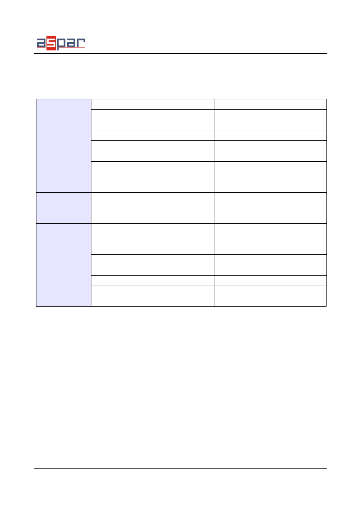
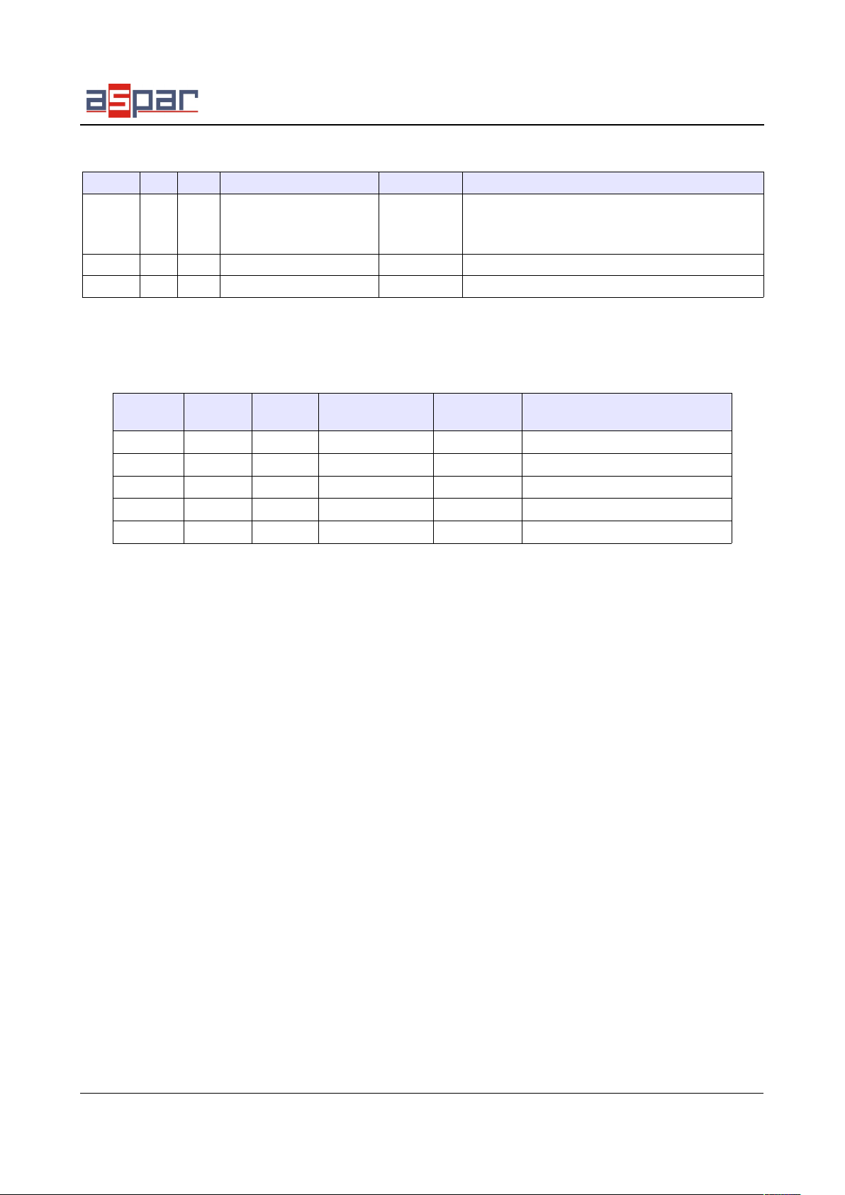
7. Modules Registers
7.1. Registered access
Modbus Dec Hex Register Name Access Description
30001 0 0x00 Version/Type Read Version and Type of the device
30002 1 0x01 Address Read Module Address
40003 2 0x02 Baud rate Read & Write RS485 baud rate
40004 3 0x03 Stop Bits & Data Bits Read & Write No of Stop bits & Data Bits (see 3.4.2)
40005 4 0x04 Parity Read & Write Parity bit
40006 5 0x05 Response Delay Read & Write Response delay in ms
4000 6 0x06 Modbus Mode Read & Write Modbus Mode (ASCII or RTU)
40010 9 0x09 Filter Read & Write Measurement filtering, value from 1 to 10
40033 32 0x20 Received packets MSB Read & Write No of received packets
40034 33 0x21 Received packets LSB Read & Write
40035 34 0x22 Incorrect packets MSB Read & Write No of received packets with error
40036 35 0x23 Incorrect packets LSB Read & Write
4003 36 0x24 Sent packets MSB Read & Write No of sent packets
40038 3 0x25 Sent packets LSB Read & Write
30051 50 0x32 Inputs Read Connected inputs
Bit in high state → signal is connected
40052 51 0x33 Outputs Read & Write Alarms state
bit no. 3 digital output
30053 52 0x34 Voltage Read Voltage in μV
30054 53 0x35 Current Read Current in μA or ‰
30055 54 0x36 Alarm – max voltage Read & Write Maximum value of voltage excess which causes set
bit no 1 in the register 40052
30056 55 0x3 Alarm – min voltage Read & Write Minimum value of voltage. If voltage drops below
this voltage bit no 1 in the register 40052 is set.
3005 56 0x38 Alarm – max current Read & Write Maximum value of current excess which causes set
bit no 1 in the register 40052
30058 5 0x39 Alarm – min current Read & Write Minimum value of current. If current drops below
this voltage bit no 1 in the register 40052 is set.
30059 58 0x3A Voltage alarm configuration Read & Write Alarms configuration
0 – alarms state depends on actual values
1 – alarms state need to clear by master
30060 59 0x3B Current alarm configuration Read & Write
30061 60 0x3C Voltage input configuration Read & Write
0 – OFF
1 – 0 .. 10V
2 – -10 .. 10V
3 – 0 .. 1V
4 – -1 .. 1V
40062 61 0x3D Current input configuration Read & Write
0 – OFF
1 – 0 .. 20mA (in μA)
2 – 4 .. 20mA (in ‰)
3 – -20mA .. 20mA (in μA)
40063 62 0x3E Digital output configuration Read & Write Digital output configuration
0 – output controlled by master
1 – output state depends voltage
2 – output state depends current
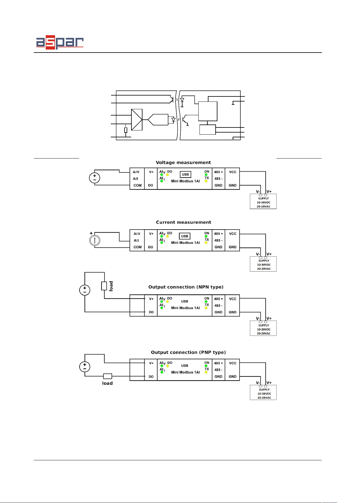
Expansion Module – 1 analog input, 1 digital output
User Manual Version 1.3 9 / 12