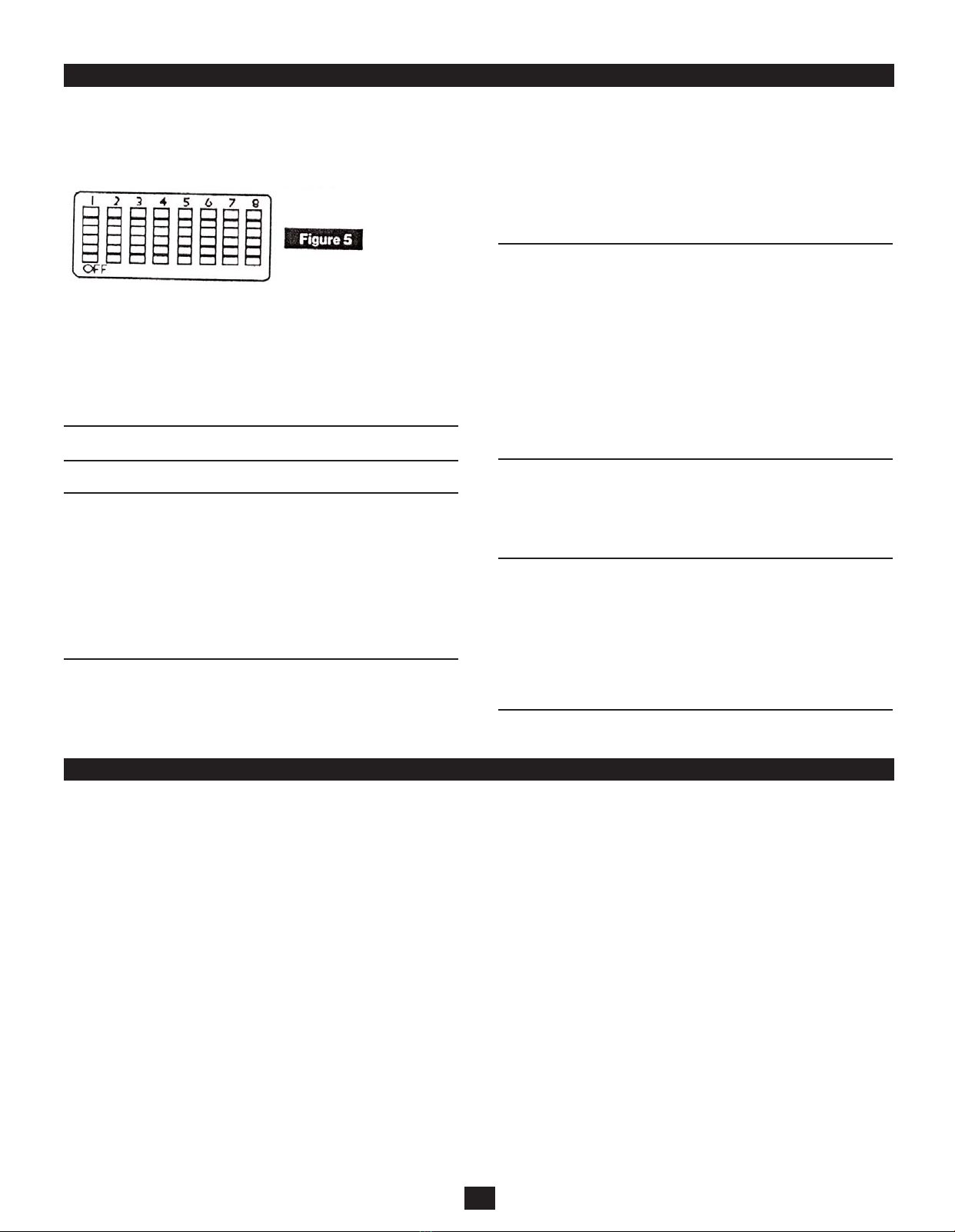
Love CR10 User manual

Bulletin E-90-CR10
CR10
Temperature, Humidity & Dew
Point Recorder
LOVE CONTROLS Division of Dwyer Instruments, Inc.
Michigan City, IN U.S.A. 46360
OPERATION MANUAL
E-90-CR10 6/22/05 3:14 PM Page 1

Quick Start
Your CR10 recorder has been preset to operate using the most
popular settings.
Recording Time: 7 day
°F/°C: °F
Temperature Range: -20 - +120°F
Variables Recorded: °F and %RH
Pens and a chart have already been installed for your conve-
nience. All you need to do to start using your CR10 recorder with
the settings listed above is follow these quick start instructions:
1. Plug in the AC adapter.
2. Set the appropriate time by inserting a coin into the groove in
the chart hub and turning clockwise until the correct hour and
day on the chart is referenced to the timing clip. (see
“Instrument Anatomy” on page 4, if you need assistance
locating instrument parts)
3. Remove the protective pen caps.
4. Press the “On/Off” key and the pens will move to the current
reading.
After you get started using the “Quick Start Instruction”, we rec-
ommend that you also read the rest of the manual to ensure that
you get the most out of your instrument.
Requires 4 “D” size batteries for battery back up.
Specifications
Ranges:
• Temperature: -20 to +120°F (-20 to +50°C)
+40 to +110°F (+5 to +40°C)
• Humidity Range: 0 to 95% RH (non-condensing)
• Dew Point: -22 to +122°F (-30 to +50°C)
Sensors:
• Temperature: Thermistor
• Humidity: Thin Film Capacitor
Accuracy:
• Temperature: ±1.8°F (±1°C)
• Humidity: ±2% RH between 0 and 60%
±3% RH between 61 and 95%
•Dew Point: 95% to 30% RH +2C -2C
30% to 10% RH +4C -3C
10% to 5% RH +8C -7C
5% to 0% RH +49C -48C
Probe: .92˝ diameter x 5.9˝ long on an 8˝
cord (2.3cm x 15cm long on a
20.3cm cord)
Recording Times: 1, 7, 14 & 31 day
Average Response Time:
• Temperature: 30 seconds for 63% step change at 1CFM air-
flow
• Humidity: 20 seconds to move 63% step change at 1 CFM
Chart: 8˝ diameter (20.3cm)
Display Resolution:
1°F (1°C), 1% RH
Ambient Operating Conditions (body):
0 to 90% RH, +32 to +122°F (0 to +50° C)
Power Supply: 120V AC adapter with 4 “D” batteries for back-
up power
Average Battery Life:
In 1-day recording mode=2 months,
7-day mode=3 months,
31-day mode=4 months
Note: Response time is slower when using battery power source.
Calibration: User calibration of zero
Alarms: Audio/visual - high and low
(warning mechanism, no controller functions)
Mounting: Free standing or wall mounting
(keyholes)
Dimensions: 10.5˝ x 13.2˝ x 2.8˝
(26.7cm x 33.5cm x 7.1cm)
Weight: Approximately 7 lbs. (3.1kg) with batteries
2
E-90-CR10 6/22/05 3:14 PM Page 2

Instrument Anatomy
3
E-90-CR10 6/22/05 3:14 PM Page 3

Operating Information
Pens
The blue pen has a longer pen arm and records humidity or dew
point (depending on your dip switch selection, see page 6) and the
red pen has a shorter arm and records temperature. The pens are
offset to allow the red pen to glide under the blue pen. The blue
pen indicates the correct time and the red pen precedes it by 3/16˝
of an inch.
The pens move in increments across the chart as sensor readings
change. The display provides smoother and faster readings than
the pens. At any given time there may be a slight discrepancy in
the position of the pen and the reading on the display due to hys-
teresis.
For visual spot checks the display is more accurate than the pen
position but both are within the stated specifications of the units.
(See “Specifications” on page 2)
Pen Adjust
Pen adjustment may be needed if the pens and display do not
match exactly
1. Make sure the pen lifting bar is lowered and press the “Pen
Home” key.
2. Turn the chart hub clockwise rotating the chart.
3. With a small screwdriver loosen the pen adjust screw on the
pen arms and adjust the pen tips to the outer most circle on
the chart.
4. Retighten the screws. After pressing “Pen Home” again the
pens should now read correctly with the display.
Probe
The CR10 probe sits in the cradle in the back of the unit. The CR10
probe comes with the standard 8˝ cord. An extension cord can be
ordered to allow for remote sensing capabilities. (See
“Replacement Parts” on page 8)
Cord Installation
If you have ordered an extension cord for remote sensing capabil-
ities follow the instructions for cord installation listed below:
1. Turn the unit upside down or on its side so that you can see
where the probe connects to the back of the CR10.
2. Twist and pull the black rubber strain relief, beginning on the
back of the recorder body. (See “Instrument Anatomy” on page
4)
3. Slide the strain relief down the cord.
4. Inside you will see a standard connector which looks like a
phone jack. Using a small screwdriver, press retention tab and
the connector will pop out easily.
5. Remove wand from cradle by sliding upward. Repeat steps 1
through 3 for the portion of the cord that connects to the wand.
6. Return the wand to the cradle mounted position by sliding the
wand down into the cradle until it fits into the grips. The probe
can also be replaced by positioning it in back of the cradle area
and pressing it into the cradle until it snaps in place.
Power Supply
We recommend using AC power with four “D” batteries installed as
a back-up power source. This ensures that your recording will not
be interrupted when there is a power failure. When the instrument
is using battery power, the unit will update very slowly to extend
battery life. The 120V AC adapter plugs into the back of the
recorder beneath the probe cradle.
Display Symbols
Alarm is on.
LO BATT
Low battery indicator.
UC
User Calibration mode. This is displayed in the upper right hand
corner of the display.
Reading update indicator. These rectangles will flash along the bot-
tom of the display as long as the recorder is taking readings. If you
are using batteries as the power source the update indicator rec-
tangles will still flash but the rate will be very slow in some modes
and “B” will light on display. The rectangle furthest to the right is lit
continuously when the unit is using battery power.
MIN
This symbol is displayed when you are setting a minimum alarm or
when you have pressed the “Min/Max” key and the minimum value
is being displayed.
MAX
This symbol is displayed when you are setting a maximum alarm or
when you have pressed the “Min/Max” key and the maximum value
is being displayed.
4
E-90-CR10 6/22/05 3:14 PM Page 4

Keypad Operations
On/Off
When you press the “On/Off” key the pens will move to the
correct reading.
Alarm Set
The alarm set keys are labeled with arrows that point up and down.
You can set a minimum and maximum alarm for both of the two
variables you are recording.
1. To set the alarms press the “Alarm Set” key. The MIN symbol
will be displayed and the temperature will flash. (Note: The
alarm set function always starts with temperature. If you do not
want an alarm to sound for temperature readings set the
alarms for points that are outside of your range.)
2. Use the up arrow button to increase the minimum temperature
alarm setting and the down arrow to decrease the minimum
temperature alarm setting.
3. Press “Alarm Set” key a second time. The MAX symbol will
appear and the temperature will flash indicating that you can
now set the maximum temperature alarm. Use the same pro-
cedure as in step #2 above for setting the temperature maxi-
mum alarm setting.
4. Press the “Alarm Set” key a third time and the MIN symbol will
appear and humidity (or dew point if dip switch #5 is on) will
flash. Use the same process in step 2 & 3 above to set humid-
ity and dew point alarm.
5. When you have set alarms for both variables press “Alarm Set”
a final time to lock in settings.
Alarm On/Off
This button turns the alarms on and off. When alarms are “on”, the
alarm symbol appears on the display. When alarm sounds it will
sound audibly for approximately 1 minute and then it will stop. For
a visual alarm, the variable that has moved outside of the minimum
or maximum points that you set will flash. (i.e. if you set a maximum
alarm for +80°F and the temperature reaches +80°F the tempera-
ture portion of the display will flash)
Min/Max
1. Press the “Min/Max” key once and the minimum value during
the recording time will be displayed for approximately 7 sec-
onds.
2. Press the “Min/Max” key again and the maximum value during
the recording time will be displayed for 7 seconds.
3. Press “Min/Max” key a third time during this period and the dis-
play will show current readings. The unit always return to cur-
rent readings mode after 7 seconds.
Note: Turning the unit off resets the minimum and maximum val-
ues.
Pen Home
Press the “Pen Home” key while the unit is operating and the pen
will move to the outside of the chart.
Press the “Pen Home” key again and the pen will return to the cur-
rent reading points on the chart.
Display Change
Press the “Display” key and the display will temporarily show the
reading opposite of what is being recorded. (i.e. if dip switch #5 is
off and you are recording the RH, pressing the “Display Change”
will temporarily change the display to show the dew point reading)
Note: If the unit does not respond to keypad, check to see that dip
switch #8 is off.
5
On/Off
Min/Max
Pen
Home
Alarm
On/Off
Alarm
Set
Display
Change
The defaults for alarm settings are:
Temperature: +40°F Min to +100°F
Humidity: 20% Min, 80% Max
Note: Alarm settings will return to the default when AC power
fails and there are no batteries installed for back-up power.
E-90-CR10 6/22/05 3:14 PM Page 5

Dip Switch Set-Up
To set-up the CR10 for your specific application you might need to
change some of the dip switches. Every time you change a dip
switch setting, you must push the up arrow key on the keypad to
activate the new dip switch settings.
Recording Time
The CR10 has four different recording time options: 1 day, 7 day,
14 day and 31 day. Dip switches #1 and #2 control the recording
time.
7 day #1 Off
#2 Off
1 day #1 Off
#2 On
14 day #1 On
#2 Off
31 day #1 On
#2 On
Note: Remember to install correct chart to match corresponding
switch setting.
°F/°C
You can record in °F or °C with the CR10 by using dip switch #3.
°F #3 Off
°C #3 On
Temperature Range
The CR30 will record in four temperature ranges. Dip switch #4
allows you to select the temperature range.
Wide Range #4 Off
-20 to +120°F (-20 to +50°C)
Narrow Range #4 On
+40 to +110°F (+5 to +40°C)
RH/Dew Point
Dip switch #5 allows you to select whether RH or dew point is
recorded by the blue pen. (The red pen always records tempera-
ture.)
RH #5 Off
Dew Point #5 On
Note: When the blue pen is recording dew point, the reading indi-
cates the temperature at which dew will form, so you should use
the temperature scale on the chart to read dew point.
Display
The CR10 has a dual display that shows both temperature and
humidity (or temperature and dew point if dip switch #5 is on). With
dip switch #6 you can control the position of the variables dis-
played.
Temperature on top #6 Off
Temperature on bottom #6 On
Display On/Off
Dip switch #7 will allow you to turn the display on and off.
Display On #7 Off
Display Off #7 On
Keypad Lock
For security purposes it is possible to lock the keypad to prevent
unauthorized persons from using the keypad to set alarms or
change the calibration. (For more information on use of the keypad
see “Keypad Operation” on page 6 & 7)
Keypad Unlocked #8 Off
Keypad Locked #8 On
Calibration
Your instrument was carefully tested and calibrated before being
shipped from the factory. Additional calibration is not required.
However, should calibration be desired in the future, identify a stan-
dard that is more accurate than this unit. Calibration salt capsules
or electronic instruments recently calibrated at a certified lab are
recommended. Sling psychrometers and instruments using
mechanical sensing elements (human hair, wood elements, bimet-
als, etc.) should not be used.
Note: The unit does not have to be recalibrated if you used a
longer probe cord.
Calibrate Humidity/Dew Point
(using a controlled chamber)
1. Turn the unit on and use dip switch #5 to select humidity or
dew point. (RH = #5 Off) or (Dew Point = #5 On) Use dip switch
#3 to select °F or °C. (°F = #3 Off) or (°C = #3 On)
2. To activate the calibration mode, turn the unit off. Now press
the “On/Off” key and the “Up Arrow” key at the same time. The
“UC” symbol will appear in the display to indicate you are in
“User Calibration” mode.
3. Place the probe of the unit along with your precision relative
humidity/dew point instrument (RH/Dew Point standards), into
a controlled environment chamber and allow 15 minutes for the
unit to stabilize. For best results, calibrate the unit at levels typ-
ically monitored during normal operation.
4. Match the CR10 reading with your precision RH/Dew Point
instrument. To raise the RH/Dew Point reading press the “Up
Arrow” key. To lower the RH/Dew Point press the “Down
Arrow” key.
5. When calibration is complete, simply press the “On/Off” key to
save calibration setting.
Calibrating in an open room, without the use of a salt capsule or a
chamber, is not recommended as humidity can vary greatly within
a very small area.
6
E-90-CR10 6/22/05 3:14 PM Page 6

Chart Installation
1. Press the pen home key to make pens move to the outside of
the chart.
2. Press the pen lifting bar to raise the pens. Remove the record-
ed chart if present.
3. Place the new appropriate chart on the chart hub – being cer-
tain that the edge of the chart slides under the chart guide clips
located at the outside of the chart.
Note: The chart should lay flat on the dial face.
4. Set time by inserting a coin into the groove in the chart hub and
turning clockwise until the correct hour (and day if applicable)
on the chart is referenced to the timing clip.
5. Lower the pen lifting bar so that the pen tips rest firmly on the
paper.
6. Press the pen home key to return the pens to position. At the
end of one recording time cycle, simply repeat steps 1-5,
replacing the used chart with a new one.
7
Pen Installation
Calibration
Calibrate RH/Dew Point
(using salt capsules)
1. Turn the unit on and use dip switch #5 to select humidity or
dew point. Use dip switch #3 to select °F or °C (°F = #3 Off) or
(°C = #3 On)
2. To activate the calibration mode, turn the unit off. Now press
the “On/Off” key and the “Up Arrow” at the same time. The dis-
play should read “UC” in the upper right hand corner of the dis-
play to indicate you are in the “User Calibration” mode.
3. Place the probe of the unit into a 11% salt capsule or 75% salt
capsule, by removing the cap and inserting the probe. Allow
approximately 2 hours for the unit to stabilize.
For best results, calibrate the unit at the level typically monitored
during normal operation.
4. Match the CR10 reading with either 11% or 75%, depending
on the salt capsule being used. To raise the RH/Dew Point
reading, press the “Up Arrow” key. To lower the reading, press
the “Down Arrow” key.
5. When calibration is complete, simply press the “On/Off” key to
save calibration settings.
Calibrate Temperature
1. Press the “On/Off” key & “Up Arrow” key simultaneously to
enter the “User Calibration” mode. Use dip switch #3 to select
°F or °C. (°F = #3 Off) or (°C = #3 On) The display should read
“UC” in the upper right hand corner of the display.
2. Place the CR10 probe, along with your precision temperature
instrument (your temperature standard) into a controlled envi-
ronmental chamber allowing both instruments to completely
stabilize, approximately 1 hour.
For best results, calibrate the unit at levels typically monitored dur-
ing normal operation.
3. Match the CR10 reading with your precision temperature
instrument.
4. To raise temperature reading, press the “Alarm Set” key. To
lower the temperature reading press the “Alarm On/Off” key.
Each key press adjusts the reading by 1°F.
5. When calibration is complete, simply press the “On/Off” key to
save calibration settings.
Calibrating is stored in memory even after you turn the unit off.
User calibration information will not be lost if AC power fails.
1. Press the “Pen Home” key to return pen to the home posi-
tion.
2. Use the pen lifter to raise the pens.
3. Gently lift the cartridge slightly and slide it off the pen arm.
4. With the pen tip facing the chart, and the new pen cap off,
thread the pen arm through the sleeve on the underside of
the pen. Slide the cartridge back until you feel the notch in
the pen arm seat securely around the plastic portion of the
pen tip.
E-90-CR10 6/22/05 3:14 PM Page 7

Replacement Parts
8
Description Quantity Part#
Charts
-20° - +120°F/24-hour 100 CR721
-20° - +120°F/7-day (included) 100 CR771
-20° - +50°C/0 - 100% RH/24-hour 100` CR725
0° - +100°F/7-day 100 CR776
+40° - +110°F/0 - 100% RH/24-hour 100 CR724
Note: If you will be using the 14 day recording time, you can use a 7 day chart in the range desired and divide up each day by two.
Accessories
Replacement Pen Pack 6/pack (3 red, 3 blue) CR820
10’ Probe Extension Cable CR810
Replacement Parts
Problem
Temperature Pen and Display do not match
Instrument is not responding to key presses
Instrument turns off
Probe exposed to environments exceeding
95% RH for extended period
Alarm symbol is flashing in digital display
Display shows dc and indicator on the left
part of the digital display is lit
Display shows E(lower left of display)
Out of calibration or Questionable accuracy
Display won’t light
Unit won’t work at all
Pen trace too fine or absent
Display shows Err
Display shows Prob
Display shows cold
Display and unit are frozen
Solution
• Check dip switch setting 7 proper chart.
• May also be hysteresis, see p.4 “Pens”.
• Need for pen adjustment, see p.4 “Pen Adjust”.
• Keypad may be locked, check dip switch #8
• Slower firmer key presses (may take multiple presses)
• Check AC adapter connection (widen prongs of
adapter to fit tighter)
• Check battery installation & reinstall
• Display may be off, check dip switch #7
Probe should be dried out under normal ambient
conditions-Time required varies on Temp, RH & air flow
Alarm sounds audibly for 60 seconds if out of
range conditions occur, then indicator will flash
until alarm key is depressed & alarm is reset
(depress MIN/MAX keys for information)
Factory repair is necessary
System error or error in calibration
• Instrument exposed to harsh environments or
stressful conditions, see calibration procedure
in manual.
Check dip switch #7. Switch should be OFF.
Check both dip switch #7 & #8. Both should be
OFF to allow operation.
• Pen may need to be replaced, moistened or sanded
• Remove pen cap
Temperature being monitored is to high, see p.2
Temperature being monitored is extremely cold or
probe is disconnected
Temperature being monitored is to low, see p.2
• Reset the unit by shutting it down (unplug the AC
adapter and take the batteries out) then
restore power source and turn it on.
E-90-CR10 6/22/05 3:14 PM Page 8

Factory Service and Returns
We recommend that damaged instruments be returned to our fac-
tory for complete repair. Before returning any instrument or pack-
age, please call for a Return Authorization (RA) number.
When calling, please have the following information available:
1. P.O. number for out-of-warranty units.
2. Serial number of unit.
3. Model number of unit.
4. The problem you’re experiencing with unit.
Warranty
9
Dwyer Instruments, Inc. warrants the CR10 will be free from
defects in material and workmanship for a period of twelve months
after delivery. In the event of a claim under this warranty, the prod-
uct or part must be returned to the factory for repair or replace-
ment (shipping prepaid) with a Return Authorization Number (See
“Factory Service & Returns” information above). It will be repaired
or replaced after evaluation.
The foregoing warranty and remedy are exclusive and in lieu of all
other warranties either expressed or implied.
Dwyer shall not be liable for consequential or incidental damages
resulting from failure or malfunction or its products.
Revised 9/97
E-90-CR10 6/22/05 3:14 PM Page 9
Table of contents
Other Love Measuring Instrument manuals
Popular Measuring Instrument manuals by other brands

TESTO
TESTO 177-T1 Short instruction manual

AXIOMA METERING UAB
AXIOMA METERING UAB QALCOSONIC E2 Technical description, installation and user instructions

Analytical Technology
Analytical Technology Q25R manual

LTB
LTB MNL100 operating manual

GL McGAVIN
GL McGAVIN RESCUE FR50 DC Modiewark manual

Mircom
Mircom FleX-Net FX-4000 Installation and operation manual