Assa Abloy SMARTair Wireless User manual

SMARTair
Wireless

12/04/2016 - 2 - Concept
Table of contents
Table of contents....................................................................................................................................................................- 2 -
History–Modifications ..........................................................................................................................................................- 2 -
1System Architecture .....................................................................................................................................................- 3 -
2Door configuration .......................................................................................................................................................- 4 -
3Setting up the hub(s).....................................................................................................................................................- 6 -
3.1 Led indications....................................................................................................................................................- 6 -
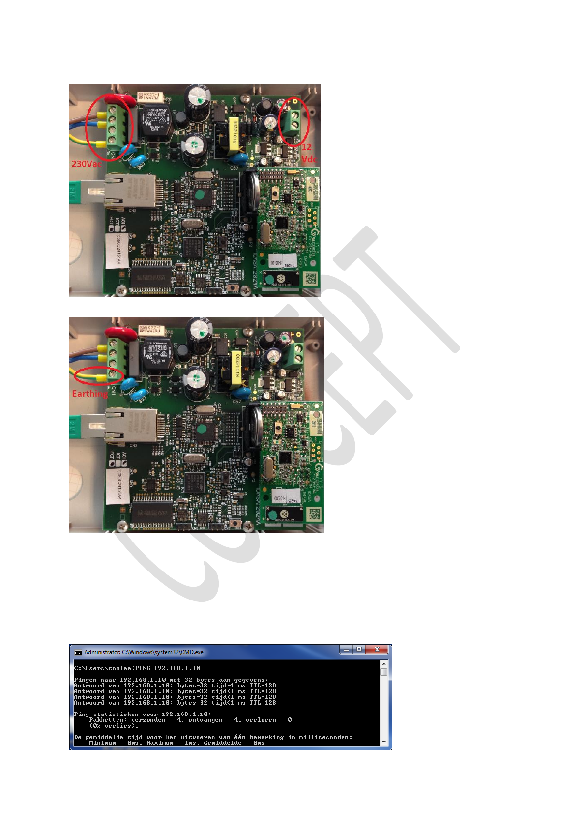
3.3 Hub connections .................................................................................................................................................- 7 -
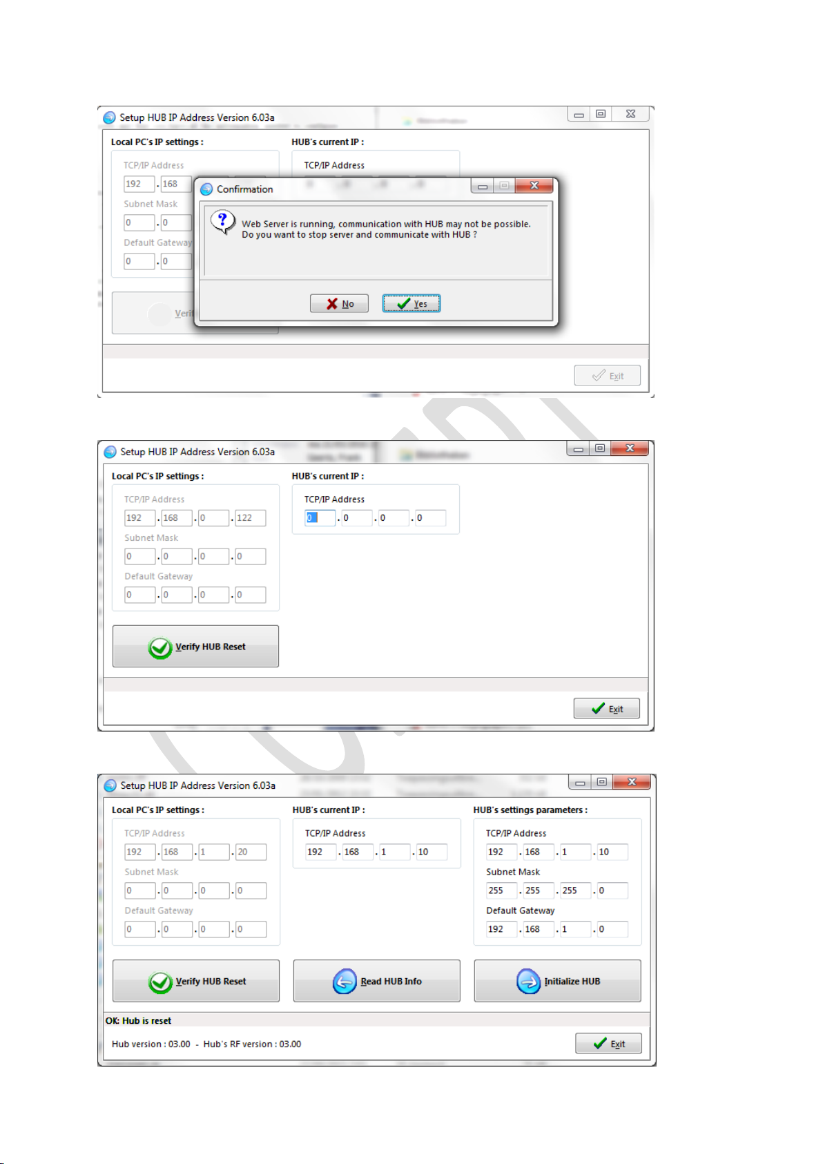
3.4 Hub IP configuration...........................................................................................................................................- 7 -
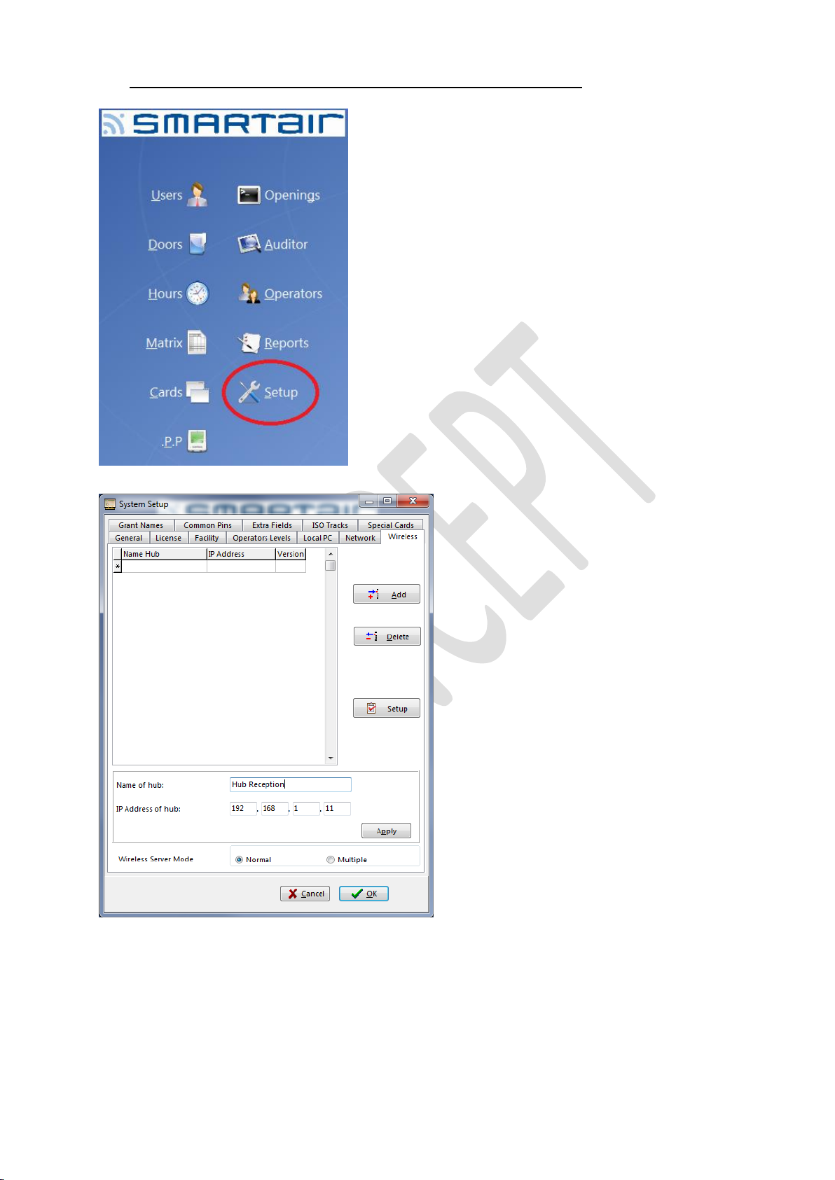
5Connecting the hub to the SMARTair TS1000...........................................................................................................- 10 -
7Pairing devices with an hub........................................................................................................................................- 13 -
9Resetting the hub back to factory default....................................................................................................................- 18 -
10 Good to know and Do’s and Don’ts ...........................................................................................................................- 18 -
10.1 Good to know....................................................................................................................................................- 18 -
10.2 Do’s ..................................................................................................................................................................- 20 -
10.3 Don ‘ts ..............................................................................................................................................................- 20 -
History– Modifications
Version
Modification
Concept
Not for distribution
V1.0
SMARTair Wireless manual TS1000 V6.03a

12/04/2016 - 3 - Concept
1System Architecture
The UOL (Update On-Line) devices can be connected through RF (Wireless) to the PC.
Hubs are connected to the PC through an Ethernet connection using the UDP protocol and with the UOL devices through RF.
The RF communication is 868 MHz and proprietary protocol. Information sent between devices is encrypted with a
proprietary protocol.
A PC can manage up to 100 hubs if needed.
A hub can manage up to 30 UOL devices in a range of around 25 meters max.
The range of the hub is site dependent and needs to be tested on site.
Possibly more or less hubs are required to make the system perform as wanted/expected.
The hub cannot be installed on the outside of the building as the minimum operating temperature is 0° Celsius.
Depending on the location of the hubs and of the devices, the number of devices per hub can be different.
A device can be connected only to one hub.
This is called pairing, once this pairing is done, communication between the hub and the lock is possible.
If the device loses the connection to the hub or the hub loses the connection to the PC, the devices will work as an Off-Line
devices and not as UoC (Update on Card) device.
This means that every urgent change will have to be done with the PP directly on the device in case of communication loss.
All the Wireless devices must have the RF module inside and the software must have the UoL license activated.

12/04/2016 - 4 - Concept
Once the license is activated and the Manage Wireless doors, Automatically update Wireless doors is activated.
A new Wireless menu will appear on the main screen of the software. (Possibly you need to close and reopen the software to
see the new menu)
The RF module inside the device can have three different states:
Always Sleep
Manufacturing
mode
RF module is switched OFF
No communication possible!
Always Awake
Initialization mode
RF module is switched ON
High Power consumption
Switches automatically back to Always Sleep if no connection is made in 1 hour.
Sleep/Awake
Standard mode
RF module is switched on every x time for ex. Door open commands.
Normal Power consumption.
It is very important to know that if the RF module is placed in Always Awake mode, an connection has to be made with this
module in order to make the device work with RF functionalities.
If no connection is made with the device in 1 hours’ time, the RF module will go back to Always Sleep mode and the device
will not communicate over RF!
2Door configuration
Configure the door device as before with Off-line or UoC devices, only make sure the technology type is Wireless!
The only new parameter to be defined for this type of doors is the wireless address.
Doors that have this parameter empty or equal to 0.0.0.0 will NOT communicate through RF.
Once the locking plan has been defined, the Portable Programmer can be loaded with the list of UOL doors.
The wireless address cannot be typed in, .it will be automatically filled in after the devices have been initialized.

12/04/2016 - 5 - Concept
After you created the locking plan Matrix, you need to load the plan into the PP and initialize the device.
During this initialization, the PP will read the RF Wireless Address of the device and store this in the PP.
After you initialized the device, connect the PP to the software and open the “Openings” menu and select “Collect openings
from PP”
Now the RF Wireless Address is registered in the system and only now the wireless device can be paired to an hub.

12/04/2016 - 6 - Concept
At this moment the Wireless devices are operational but only with Off-Line functionality.
This means the customer already can access the door with his card.
The next step is to add the hub(s) to the system.
This requires some IT knowledge and some preparation work needs to be done in advance together with the client or the IT
service of the client.
3Setting up the hub(s)
Every hub in the system requires an unique static IP address which is able to communicate with the (server) PC.
The hub ‘s use the UDP ports, 7780, 7781, 7790 and 7791
Please make sure the IT service of the client is aware of these ports and that you have all the information needed to configure
the hub(s) like IP address, Sub netmask, Gateway, ….
3.1 Led indications
Led DL1, means that there is power to the hub.
Led DL2, if this is blinking, the hub is communicating and/or performing an operation.
The RJ45 network connector has two status led ‘s, one green and one yellow.
The green led indicates activity on the port (cable connected on both sides)
The yellow led blinks every time there is an signal on the RJ45 port.

12/04/2016 - 7 - Concept
3.3 Hub connections
The hub requires a power supply and an network cable connected to the network of the client.
The power supply can be an 230 Vac connection or an 12Vdc connection. Do not connect them both at the same time!
PoE is not supported by the hub!
Please pay attention to the earthing connection of the 230Vac connection, this must be always connected when using 230Vac.
3.4 Hub IP configuration
Connect the hub to your PC using an Crossed cable (delivered with the hub).
Make sure the IP address of your PC is in the same range as the default IP address of the hub.
The default IP address of the hub is: 192.168.1.10 –255.255.255.0 –192.168.1.0
Please set your IP address to for example:192.168.1.30 –255.255.255.0 –192.168.1.0
You can test the connection by opening the DOS command windows and Ping the default IP address of the hub.
The reply must be ok before continuing to the next step.
Open the InitHubIP.exe program on your PC (installed in the TS1000 folder)
As of version 6.03 of this software no further action must be taken to run this program.

12/04/2016 - 8 - Concept
In lower version of the TS1000, the services of the TS1000 software must be stopped before this program can be used.
This newer version will check if these services are still running and will ask if these services may be stopped.
Accept that the services may be stopped.
The program will stop every service necessary and continue the process.
This can take some time depending on your PC configuration.
If this is an complete new hub (never been used before)
Reset the hub and click on the Verify HUB Reset button. See procedure point 8
On the left you will see your own IP address of your PC.
In the middle, you will see the current IP address of the hub.

12/04/2016 - 9 - Concept
On the right you must fill in the new IP address of this hub and click Initialize HUB.
The hub is now being initialized with the new IP address (in the example 192.168.1.11).
If OK, click on the exit button.
The program will ask you if you would like the services stopped previously to be started again, click on Yes.
The program will start every service necessary and continue the process.
This can take some time depending on your PC configuration.
The hub is now setup correctly and we can now connect the hub to the SMARTair TS1000 software.

12/04/2016 - 10 - Concept
5Connecting the hub to the SMARTair TS1000
Open the SMARTair TS1000 software and select the Setup menu
Select the Wireless tab and enter the Name of the hub and it’s IP address.
If all information is entered, click on Apply.
The hub will now be available in the system.

12/04/2016 - 11 - Concept
Select the newly added hub and click on Setup.

12/04/2016 - 12 - Concept
Click on the correct hub and click on Start Diagnostics
If communication to the hub is OK, the RF version of the hub must now appear and an Green Check in communication.
Once this is done, the hub is up and running and we can start pairing devices to the hub.
For this we need that the door devices are up and running and that the RF Wireless address is filled in in the doors menu.
If this is not the case, follow first the steps in point 2.
We can now proceed to pair devices with the hub.

12/04/2016 - 13 - Concept
7Pairing devices with an hub
Now we need to create a special card called “Init Wireless Card”.
For this we need to exit the Wireless setup and select the tab Special Cards.
Make sure that the card encoder is connected to the computer and that you have an card available.
Please note that all data on this card will be deleted and that this is an special card that only should be used when setting up
wireless devices and therefore you should keep this card in an special/secure place!
Place the card on the encoder and click on the “Init Wireless Card” button.
If the card is programmed correctly will be indicated on the bottom of the screen.
This card can be used for all wireless devices and this card will never expire.

12/04/2016 - 14 - Concept
Now select the Wireless tab again and select the hub you wish to pair devices to and click on Setup.
First we click on Start Diagnostics to make sure we can still communicate with the hub as this is not shown at the moment.
If we see the Green check, we can proceed.
We must now go to the first device we want to pair with this hub and present the special Init Wireless Card to the device.
Make sure the device responds with an green led.
The use of this card will change the RF module state from Always Sleep to Always Awake for 1 hour.
This means that we have one hour to pair this device to an hub, if we do not pair this device to an hub, the device will go
back to Always Sleep mode and no RF communication will be possible!
After presenting the Init Wireless Card to the device we select the Search New RFs button.
If the device is in range and Awake, the RF device will be displayed below the Hub.

12/04/2016 - 15 - Concept
Notice the device is in Always Awake mode, that the device is not Assigned/Paired with the hub and we can see the signal
strength of the RF communication.
If you are happy with the signal strength (best 3 bars are more, 2 or 1 bar is not good) you can assign/pair this device to this
hub by selecting the device you want to pair and click on Add RF.
Once the device is added to the hub, you will see that the properties have changed to Assigned.
Notice that the device is still in Always Awake mode, we now must click on the Start RF button to change the State of the RF
module into Standard mode.

12/04/2016 - 16 - Concept
Once the device is Assigned/Paired and the RF module is in Standard Mode, the device is connected to the system and up and
running.
The customer will only use the Wireless menu on the main page to do his daily configurations.
All the connected devices are shown in this menu.

12/04/2016 - 17 - Concept
Select a device and click on Start Diagnostics to see if communication is possible to that device.
If the Green check is shown, this is good.
The signal strength is also updated every time the Diagnostics is started. This is not updated automatically!
For more details on the use of the Wireless menu, please refer to the specific SMARTair TS1000 manual.

12/04/2016 - 18 - Concept
9Resetting the hub back to factory default
First power off the hub, then press the indicated button and power up the hub while pressing this button for at least 10
seconds.
Release the button and allow the hub to start up.
The hub has now been reset to factory default (default IP address).
10 Good to know and Do’s and Don’ts
10.1Good to know
The RF modules of the readers are in the outside part.
The RF module of the Cylinders are in the outside part.
The RF modules of the Escutcheon are on the Inside part.
Windows can have a metallic layer and therefore block the RF signal.
The automatic update function (setup screenshot point 1) will only function if the software is running.
If you completely exit the software, the automatic update will also stop working.
Once you start up the software, the automatic update will start again.

12/04/2016 - 19 - Concept
In the Wireless menu, if we Start Diagnostics and we see , this means there is no communication from PC to the
hub. Check the network of the client and that the hub has power.
In the Wireless menu, if we Start Diagnostics and we see , this means there is no communication from hub to the
device. Check that the device is working, that the RF module is not in Always Sleep mode. This can be done using the PP.
Use the doors menu to test the device and see the RF module status.
If the RF module is in Always Sleep mode, go to point 7
The RF range can be visualized as below ( the black part is the RF antenna of the module)
Note that the signals goes in both directions, so if the hub is mounted on a wall, is signal also goes through the wall, but not
as strong of course…

12/04/2016 - 20 - Concept
10.2Do’s
Do test the location and the number of hub’s needed on side before fixing them to the wall.
The number of hub’s are very dependent on the building, it’s interior and the overall environment.
The number of hub’s cannot be defined in advance or on paper…
Do install the hub in a vertical position on the wall.
10.3Don ‘ts
Do not install the hubs outside.
Do not install a hub near metallic elements.
Do not install a hub near structure cables.
Do not install a hub inside a false ceiling.
Do not install a hub within a distance of 3 meters of a Wi-Fi Network Access Point.
Do not install a hub within a distance of 5 meters of a microwave source.
Do not install a hub when mirrors are between the hub and the lock (mirrors reflect the signals).
Do not install hubs when more than two walls are between the hub and the device.
Do not install readers on a metallic surface.
Do not install the hub on the ceiling.
Table of contents
Other Assa Abloy Network Hardware manuals