3.1
3. TECHNICAL DESCRIPTION
GENERAL
The two types of lubricator are of similar design and consist of:
Top section I –lubricant reservoir with pre-feeder
Intermediate section II –pump mechanism
Bottom section III –drive unit
MODE OF OPERATION
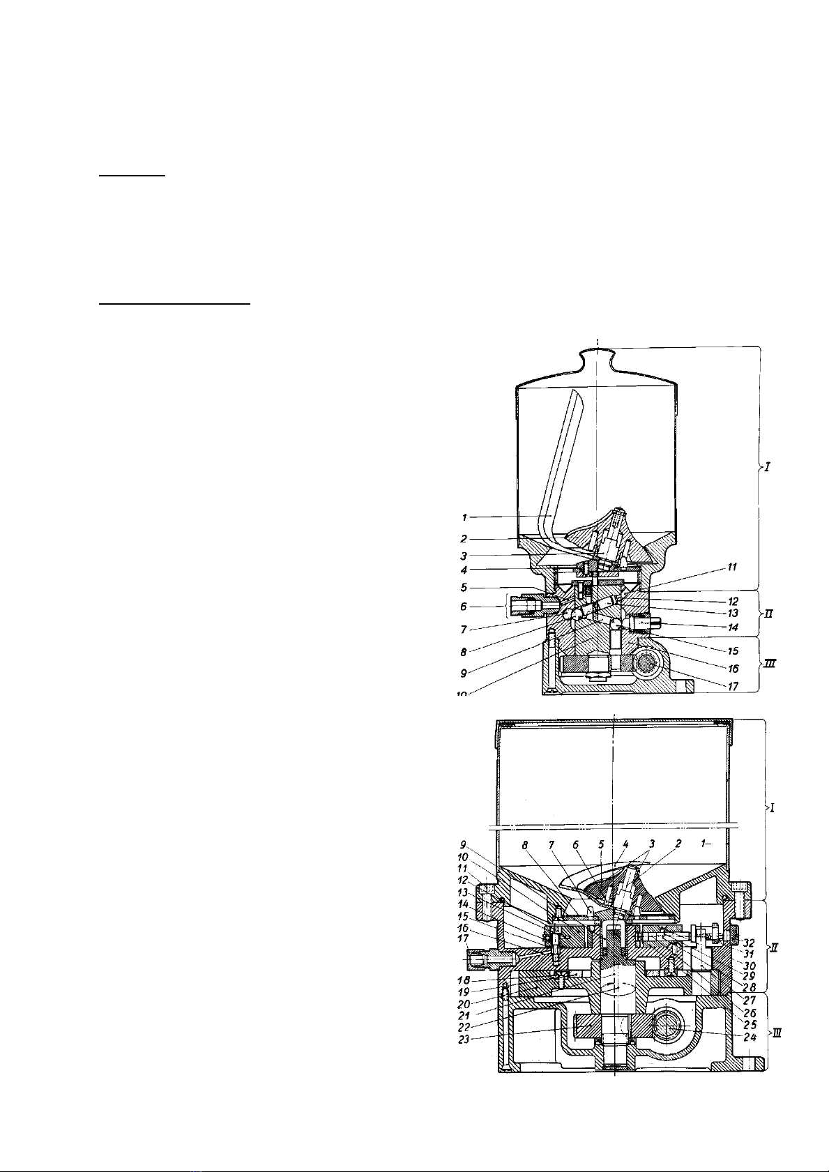
Type FL
When the central shaft 10 rotates, driven by shaft 17, the
pre-feeder (consisting of vane 1, pre-feed roller 2and
angled pin 3) feeds lubricant from the reservoir down
through the strainer 4to the cylinder pump 13 via the inlet
passages 11 in the pump body 16. The figure shows the
situation when the pump cylinder is being filled with
lubricant. When the central shaft continues to rotate, the
pump plunger pressure ball 8presses the pump plunger
upwards when it passes the pressure ball of the
respective outlet. At the same time, the orifice 12 of the
cylinder passage also passes one of the outlet passages
5in the pump body and the lubricant is forced out into
the line to the lubricating point via outlet 6. The pump
plunger then gets its suction movement from pin 9when
the guiding ball 15 in the central shaft engages with the
setting screw 14. Each outlet has a pressure ball 7, a
setting screw 14, an inlet passage 11 and an outlet
passage 5. The setting screws 14 adjust the length of the
pump plunger stroke and thus the lubricant discharge.
The lubricant discharge rate set for each outlet is
completely independent of those of the other outlets.
Type FE
When the central shaft 21 rotates, driven by shaft 24,
the pre-feeder 2–6feeds lubricant from the reservoir
through the strainer 8to the inlet 30 of the respective
pump unit 10. At the same time, the eccentric on the
central shaft and the guide plate 19 impart a plane-
parallel circular motion to the pump disc 20. By this
means the pressure studs 27 give the pump plungers
28 their axial suction and pressure motion, with the
rotational motion at dead centre which places the pump
unit cylinder 26 alternately in communication with the
intake opening 30 and the discharge connection 17 via
passages 13 and 16.
The central shaft drives the pre-feeder via the driver 9.
The pre-feeder homogenizes the grease and renders it
free from air.
The discharge rate is set individually for each pump unit
by adjusting the stroke of the pump plunger with the
setting screw 31. The setting screws are accessible
after removal of the protective plugs 32.
The pump units are readily accessible for replacement
after removal of the top section.