4/4
OPERATION / TESTING / MAINTENANCE
OPERATION
When AC power is applied, the LED test switch is illuminated, indicating that the batteries are being charged. When AC
power fails, the Si-36 automatically switches to emergency power, operating the lighting load at approximately 30%
(Reprogrammed to 20%) of rated luminaire power (max. 120W (PST @ 3 Vdc) or 180W (PST @ 2 Vdc) using Power Share
Technology. The Si-36 can also be used as a stand alone 36W inverter when used with lighting loads less than or equal to 36
watts. During power failure, the LED test switch indicator will be off. When power is restored, the Si-36 switches back to normal
mode of operation and resumes battery charging. The minimum emergency operating time is 90 minutes. The charging time for
a full discharge is 24 hours.
TESTING AND MAINTENANCE
The following Periodic testing is recommended to ensure the system is working correctly.
1. Visually inspect the LED test switch (LTS) monthly. It should be illuminated when AC power is applied.
2. Conduct a 30-second discharge test by switching off the emergency breaker every month. The LTS will be off.
3. Conduct a 90-minute discharge test once per year. The LTS will be off during test.
AUTO TEST
1. Initial Auto Test:When the system is connected properly and powered on, the Si-36will perform an initial Auto Test. If any
abnormal conditions exist, the LTS will flash rapidly*. Once the abnormal condition is corrected, the LTS will function correctly.
2. Monthly Auto Test:The Si-36will conduct the first Monthly Auto Test after 24 hours and up to 7 days after initial power on.
Then monthly tests will be performed every 30 days, and will test transfer function from normal to emergency, emergency
function, charging and discharging conditions. Monthly test time is approximately 30 seconds.
3. Annual Auto Test: It will occur every 52 weeks after the initial 24 hours full charge, and will test proper initial battery voltage,
90-minute emergency operation, and acceptable battery voltage at the end of the full 90-minute test.
*If the Auto Test is interrupted by a power failure, a full 90-minute Auto Test will occur again 24 hours after the power is restored.
If the power failure causes the battery to fully discharge, the product will restart the Initial Auto Test, Monthly and Annual Auto
Test.
MANUAL TEST
1. Press the LTS 2 times continuously within 5 seconds to force a 30-second monthly test.After the test is complete, the
next (30-day) monthly test will count from this date.
2. Press the LTS 3 times continuously within 5 seconds to force a 90-minute annual test. After the test is completed, the
next (52-week) annual test will count from this date.
3. During any manual test, press and hold the LTS for greater than 3 seconds to terminate a manual test.The Preprogra-
mmed Scheduled Auto Test time will not change.
LED TEST SWITCH CONDITIONS
LTS Slow Blinking: Normal Charging
LTS On: Battery Fully Charged - Normal Condition
LTS Off: Power Failure
LTS Gradual Change: In Testing Mode
LTS Quickly Blinking: Abnormal Condition - Corrective Action Required
**LTS (selectable 2 VDC): Long ON, Short OFF, Long ON
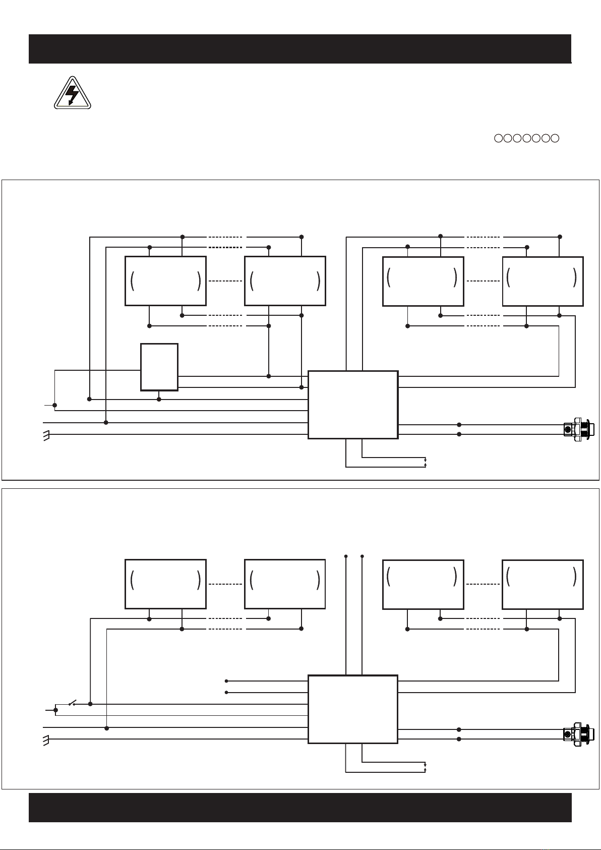
POWER SHARE TECHNOLOGY
The Si-36 utilizes Power Share Technology (PST) which allows single or multiple 0-10 Vdc controlled luminaires (up to 120W
combined normal luminaire power) to automatically adjust and share up to 36W of emergency AC power. During normal
operation, the emergency inverter will pass through normal dimming voltage (0-10 Vdc) on the dim output leads, but then supply
a default 3 VDC (or selectable **2 VDC) during emergency operation to achieve approximately 30% (or selectable **20%) of
rated luminaire power during an emergency power failure.
** Reduced output mode 2 VDC (~20%) can be selected and easily programmed via the LED test switch (LTS) by pressing
the illuminated button for 5 seconds, releasing, then repeating the 5-second button push (i.e. two 5-second extended button
pushes within a 13 second timespan). LTS flash sequence confirming 2 VDC mode: long ON, short OFF, long ON. (Return to the
default 3 VDC mode by repeating the extended button press sequence above.)
Example (default 3 Vdc setting): Three 40W LED luminaires (120W) will share 12W each of the maximum available 36W
emergency power per Si-36. 40W x 30% dim = 12W. Similarly, if each luminaire is 30W, then 4 units can 9W each; whereas if
the luminaire power is over 40W, then 2 or less luminaires can be operated.
Example (2 Vdc setting): Four 45W LED luminaires (180W) would share 9W each of the total 36W emergency power per Si-36.
45W x 20% dim = 9W * 4 luminaires = 36W. If the luminaire power is over 45W, then 3 or fewer luminaires can be operated.
See Si-36 application detail at www.AssuranceLighting.com or contact Tech Support at 1-877-774-4775.
When non-dimmable loads are used, the normal and emergency output will be 36W (max.) at temperatures of (10-55°C), 27W
for (0-55°C) and 27W for 2 hours (10-55°C).
www.AssuranceLighting.com