Rorze RD-122 User manual

Instruction Manual
2-ph Stepping Motor Driver
RD-122
RORZE CORPORATION


Be sure to read the following precautions for your safety.
This section describes safetyprecautions to avoid danger to youor someone else, to avoid damage of your property,
and to use this product safely.
Precautions before using this product
This product is designed to be incorporated into general industrial machinery, and is NOT developed to be used in devices
such as aerospace machines, security equipment, or other safety devices where a failure or malfunction of this product may
directly threaten human lives or health.
Even if you use this product in a general device, make sure that you establisha sufficient level of safetyin your device by
incorporating a protectionfunctioninto your machine and guarantee your products based onsafety tests on the whole set.
If you will use this product in devices like the above, please contact us. It should be noted that RORZE will not be
responsible for any damage caused by using a product in sucha device without the consent of RORZE.
WARNING
Ignoring the following warnings may cause a death or a serious injury.
◇Use this product at places where no explosive or flammable stuff exist nearbyand no water is splashed on the product.
Otherwise it may cause a fire and/or an injury.
◇Turn off the power before moving or wiring the product. Otherwise you may sufferinjuries or electric shocks.
◇Do not forcibly bend, pull, or nip lead wires. Otherwise they may cause anelectric shock, fire, and/or failure.
◇Do not use lead wires with their sheathdamaged. Otherwise they maycause an electric shock, fire,and/or failure.
◇Make sure that wires are correctly and securely connected at electrical terminals. Otherwise they maycause an electric
shock, fire, and/or failure.
◇Do not touch the internal parts of this product.
◇Do not disassemble or modify this product.
◇Do not wire or operate a product with wet hands. Otherwise it may causes electric shocks.
◇Assign a qualified person to transport, install, connect, operate, maintenance, or check this product. Otherwise it may
cause anelectrical shock, a fire and/oran injury.
CAUTION
Ignoring the following cautions may result in personal injuries and/or property damages.
◇Make sure that the delivered product is the one you ordered. Installing the wrong product may cause a fire and/or a
failure.
Check the following items before turning on the power.
◇The output voltage of the power supplyis as described in the specifications.
◇The voltage/current of the input/output terminals conforms to the ratings in the specifications.
◇Input/output terminals are not incorrectly wired or accidentally short-circuited.
◇Do not use with the motor except the stepping motor.
◇Operate the rated current of stepping motor within the specified input current limits only.
◇Please use the wire rod with the cross-section area corresponding to current value.
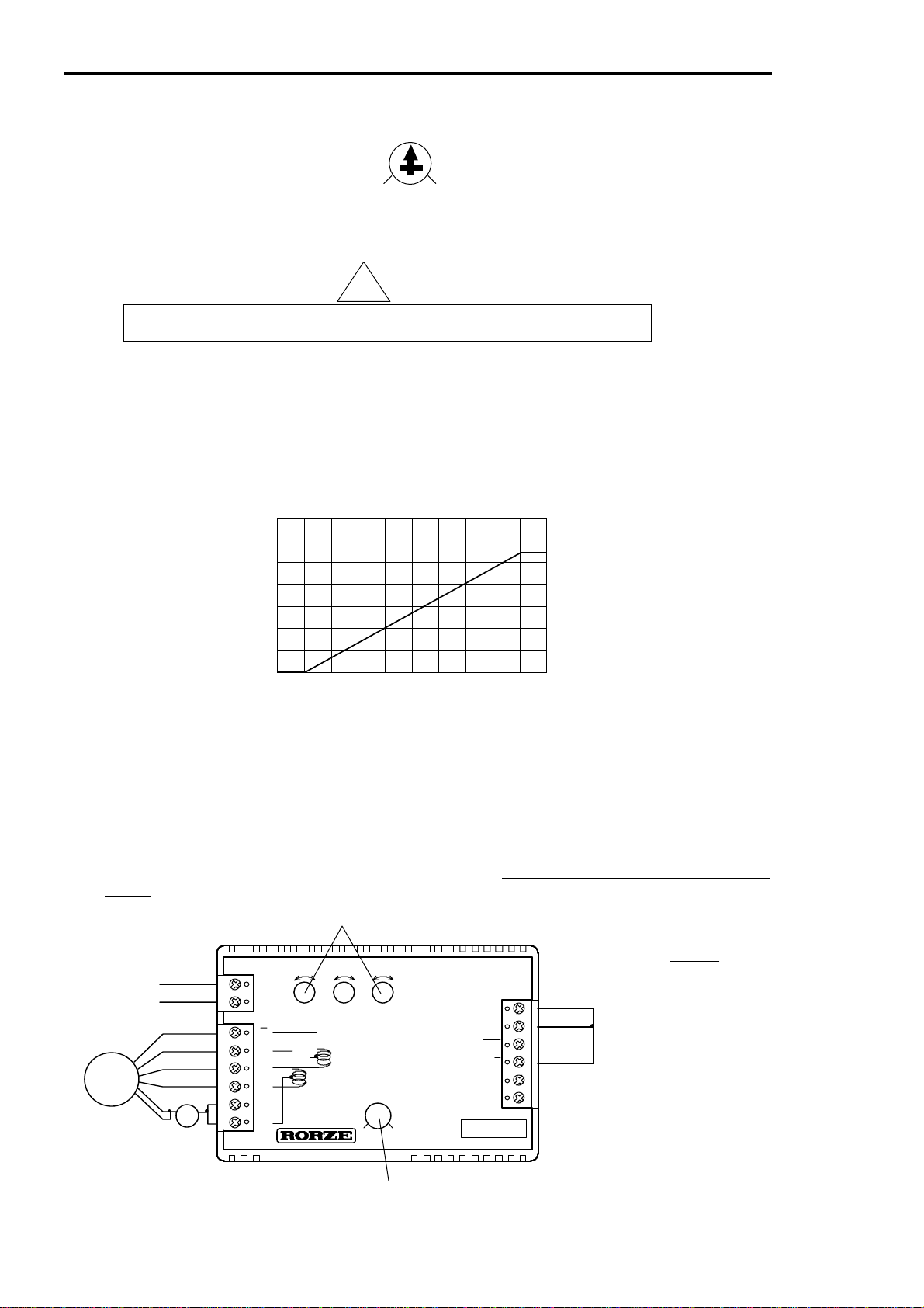
◇Because this product generates heat, please make it stick to metal board etc. or put the fan and radiate enough.
Keep the driver’s maximum temperature below 60℃.
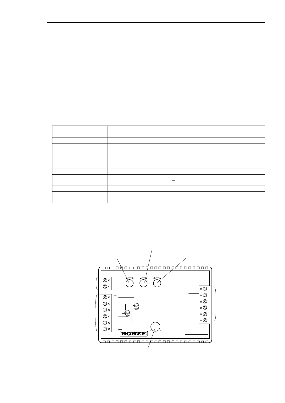
◇Whenconnecting with terminal block, use a screwdriver whose tip fits an adjustmentslot. Tighten the screw in the
torque of less than3.5kgf・cm(0.35N・m)(proper torque is 2.5kgf・cm(0.25N・m)).
◇When you run a product for the first time, make sure that the operationcan be stopped immediately under an emergency
situation.
Ignoring the above cautions may cause a fire and/or a failure.
◇Immediately turn off the power, if you hear an unusual noise. Otherwise it maycause a fire and/or an injury.
◇Do not touch this product whenit is inoperation, as a malfunction may occur.
◇Do not carry this product by holding its terminal blocks or lead wires. When the product is accidentally dropped,it may
cause a personal injury.
◇Do not place this product in unstable positions. When the product is accidentally dropped, it may cause a personal
injury.
Under some circumstances, ignoring the precaution described in the CAUTION section may also result in a death or
a severe injury.
Follow the above precautions described in both the WARNING and the CAUTION section.
!
!

Table of Contents
1.Features ..................................................................................................1
2.Specifications...........................................................................................2
3.Part Name................................................................................................2
4.Current Adjustment...................................................................................3
4-1 Current Trimmer .............................................................................3
4-2 Wiring ............................................................................................3
5.Speed Setting..........................................................................................4
5-1 High Speed Trimmer.....................................................................4
5-1 Low Speed Trimmer .....................................................................4
6.Grow Time Trimmer..................................................................................4
7.Terminals.................................................................................................5
7-1 STOP/START (Input).....................................................................5
7-2 CW/CCW (Input)...........................................................................5
7-3 SPEED H/L (Input) .......................................................................5
7-4 FREE (Input).................................................................................5
7-5 CLOCK OUT (Output)...................................................................5
8.Timing Diagrams ......................................................................................6
9.Input/Output Circuits.................................................................................7
9-1 Input Circuits (STOP/START, CW/CCW, SPEED H/L, FREE)............7
9-2 Output Circuit (CLOCK OUT)...........................................................7
10.Wiring Diagram.........................................................................................8
10-1 Suitable Motor..............................................................................8
11.Heat Dissipation .......................................................................................9
12.Other Functions........................................................................................9
12-1 Auto. current down........................................................................9
12-2 Low voltage protection circuit.........................................................9
13.Consumption Current................................................................................9
14.Relationship between Frequency(pps) and Motor speed(rpm)...................10
15.Dimensions ...........................................................................................10

1. Features 2. Specifications 3. Part Name
RD-122 1
INSTRUCTION MANUAL FOR RD-122
1.Features
・Can drive 1.3A/phase motor
・Large supply voltage range (18 to 40VDC)
・Circuit protection to protect against low voltage
・Auto current down circuit to reduce heat generation when motor is stationary
・Built-in oscillator makes PLC - or computer – control possible
2.Specifications
Supply voltage Single 18 to 40VDC (including ripple)
Supply current Approx. 2.4 times rated coil current of motor (max.)
Motor current 0 to 1.3A/phase (Adjustable by Current Adjustment Trimmer)
Drive method Unipolar, constant current chopper method
Excitation method Full step(2P)
Auto. current down 50% of the rated current after about 0.3 seconds of inactivity
Protective circuitry Low voltage protection
Oscillating frequency 7 kpps max.
Accel.,/Decel. time 200msec to 2sec
(when you change SPEED H/L terminal from 0V to 5V.or from 5V to 0V)
Speed change function Digital (High/Low)
Weight Approx. 250g (8.8oz.)
Outside dimensions 27.5H x 105W x 56Dmm (1.1”H x 4.1”W x 2.2”D)
3.Part Name
Fig.1. Name Plate
GND
010
DC
-+ S
L-+
CLOCKOUT
FREE
SPEED H/L
CW/CCW
STOP/START
GND
CURRENT
18V-
40V LOW
SPEED GROW
TIME HIGH
SPEED
C1
C2
A
A
B
B
2P PULSE MOTOR DRIVER
RD-122
MADE IN JAPAN
POWER SUPPLY
MOTOR OUTPUT INPUT/ OUTPUT
CURRENT Adjustment Trimmer
GROW TIME Trimmer
LOW SPEED Trimmer HIGH SPEED Trimmer

4. Current Adjustment
2
4.Current Adjustment
Fig.2. Current Setting Trimmer
4-1 Current Adjustment Trimmer
Caution
Please use after adjusting the current within the motor rated current.
Exceeding the rated current causes the failure of motor or fire.
This is used to adjust the stepping motor drive current and in general it makes twice to the rated
current.
If a motor is used at a high rpm with a lower-than-rated torque, better efficiency and less
temperature rise can be obtained by using the motor with a current lower than the rated value.
(Note: As the current decreases, the torque will lower.)
The drive current changes relative to the dial. The value of the setting will be ±10 % of the set
value.
Fig.3. Current Setting
4-2 Wiring
In order to measure the exact drive current, connect an ammeter as shown in the 4. “Wiring
dimension” and follow the next instructions.
1. Turn on the power after setting High Speed and Low Speed Trimmer to the minimum value.
2. As reading at the ammeter, adjust Current Trimmer and set to twice value of the rated current
/phase.
Fig.4. Wiring dimension
M
GN
D
18-40VD
C
A
A
MMETER
Set to the desired motor run current
Connect STOP/START and
SPEED H/L to GND
Set the minimum for High and Low Speed
GND
010
DC
-+ S
L-+
CLOCKOUT
FREE
SPEED H/L
CW/CCW
STOP/START
GND
CURRENT
18V-
40V LOW
SPEED GROW
TIME HIGH
SPEED
C1
C2
A
A
B
B
2P PULSE MOTOR DRIVER
RD-122
MADE IN JA PAN
012345678910
Current VR Graduations
Drive Current (A)
1
2
0
3
CURREN
T
0 10
!

5. Speed Setting 6. Grow Time Trimmer
RD-122 3
5.Speed Setting
Caution
Set the speed after setting Current Adjustment Trimmer to MIN or
removing motor wire. Setting the speed during motion is dangerous
because it may result in serious result.
☆How to set Low/High Speed of RD-122
Owing to the structure of the internal circuit, setting Low Speed
trimmer will make high speed change and vice versa.
Therefore, when setting oscillating frequency please follow the
below instructions. Fig.5. Speed Setting Trimmers
1)Connect STOP/START terminal to GND potential.
2)Turn SPEED H/L terminal to High level (open) and then set High Speed trimmer to high
speed frequency that meets your application specifications.
3)Turn SPEED H/L terminal to Low level (connects to GND potential) and then set Low Speed
trimmer to low speed frequency that meets your application specifications.
4)Review 2 and 3 to verify whether the value meets your application specifications or not.
5-1 High Speed Trimmer
This trimmer is used for setting the high speed. Setting this trimmer can make the frequency
change. Turn SPEED H/L terminal to High level (open) and then set High Speed trimmer to your
desired speed frequency. (The Max. of the setting value is approx. 7,000pps=2,100rpm/1.8゚)
5-2 Low Speed Trimmer
This trimmer is used for setting the low speed. To set this pot, turn SPEED H/L terminal to Low
level (connects to GND potential) and then set low speed to your desired speed frequency.
6.Grow Time Trimmer
Trimmer to adjust the duration of time in which the motor’s rpm changes from the stationary state to
the rpm set for High Speed and then to the rpm set for the Low Speed.
Adjustable range: 200msec. to 2sec. (When SPEED H/L voltage is changed from 0 to 5Vdc or
from 5 to 0Vdc.)
Fig.6 GROW TIME
!
LOW GROW HIGH
SPEED TIME SPEED
-+L S -+
SPEED
TIME
LOW SPEED
Adjustable by Grow Time Trimmer
HIGH SPEED

7. Terminals
4
7.Terminals
7-1 STOP/START (Input)
Turning STOP/START input to Low level (connecting to GND potential) will make the motor start to
run and the driver outputs CLOCK OUT signal to motor.
Turning STOP/START input to High level (open) will make the motor stop and the driver stops to
output CLOCK OUT signal.
7-2 CW/CCW (Input)
Turning CW/CCW to Low level (connecting to GND potential) will make the motor rotate in CCW
direction.
Turning CW/CCW to High level (open) will make the motor rotate in CW direction.
Fig.7 Direction of Rotation
7-3 SPEED H/L (Input)
This input is used for changing speed. Turning this SPEED H/L input terminal to High level (open)
or Low level (connecting to GND potential) will change the frequency to the value set by Low Speed
trimmer or High Speed trimmer.
7-4 FREE (Input)
Stepping motor drive current turns OFF at Low level (connects to GND potential) and the motor
shaft can be rotated by hand.
When turning FREE input to High level (open) again, the motor is excited at the phase home.
NOTE: Do not turn this input ON when motor is running at high speed, this operation would
damage the amplifier circuits.
7-5 CLOCK OUT (Output)
This is a terminal to output clock pulses. One pulse is putout every time a motor rotatesone step.
The driver outputs 1 pulse every time the motor rotatesby full step (1.8゚).
The duty of output clock pulse is approx. 40 to 60%.
CCW CW

8. Timing Diagrams
RD-122 5
8.Timing Diagrams
Fig.8. 2-phase Excitation Method (full step)
Fig.9. Timing Diagram Ⅱ
Fig.10. Timing Diagram Ⅲ
T2: Changing direction of rotation from CW to CCW or vice versa should be done at least 10msec
after stopping. (T2>10msec)
T3: If the motor has been idle for more than 0msec, the direction can be changed at any time.
(T3≧0msec)
T2 T3
CLOCK OU
T
STOP/STAR
T
CW/CC
W
HIGH SPEED
LOW SPEED
T1
STOP/STAR
T
H
SPEED H/L
L
HIGH SPEE
D
LOW SPEE
D
Motor drive curren
t
Current down
0.3sec
T2
1step
CLOCK OUT
A
B
A
B
ON
OFF
ON
OFF
ON
OFF
ON
OFF
Open
L

9. Input/Output Circuits
6
9.Input/Output Circuits
Caution
Do not exceed max. rated current・voltage of each I/O circuit.
It causes failure or malfunction.
9-1 Input circuits (STOP/START, CW/CCW, SPEED H/L, FREE)
Low Level: Less than 1.5V
High Level: More than 3.5V Fig.11. Input Circuits
9-2 Output Circuit (CLOCK OUT)
VOL(low level output Ic=10mA) = 0.38V
VOL(low level output Ic= 1mA) = 0.22V
Fig.12. Output Circuit
Do not supply the voltage more than 50V, the current more than 100mA to this terminal.
Inside
CLOCK OUT
Vceo = 50V
Ic = 100m
A
10KΩ18Ω
10KΩ
!
Inside
CMOS
74HC
STOP/START
CW/CCW
SPEED H/L
FREE 220
p
F
5V
10KΩ
2.2KΩ

10. Wiring Diagram
RD-122 7
10.Wiring Diagram
Caution
Make sure that there are no mis-wiring and short-circuiting and do not turn power
on before wiring correctly. There is danger of fire or failure.
Please tighten the terminals with the torque of less than 3.5kgf・cm (0.35N・m).
Please use the wire rod with the cross-section area corresponding to current value.
Use twisted wire pair for the signal input wiring. Please tighten the terminals less than 3.5kgf・cm
(0.35N・m). (Proper torque is 2.5kgf・cm (0.25N・m))
Fig.13. Wiring Diagram
10-1 Suitable Motor
You can use any HB(hybrid) or PM(permanent magnet) stepping motor with rating of 0 to 1.3A/ph.
Select motors with rating of less than supply voltage ×0.7(V).
RORZE 2-Ph Stepping Motors (Torque -- 1kgf・cm = 13.9oz・in Inertia -- 1g・c㎡= 5.46745×10⁻³oz・in2)
Holding
Torque
ModelNo. (kgf・cm) (N・m)
FullStep
Angle
(Degree)
Rated
Current
(A/ph)
Rotor
Inertia
(g・c㎡)
Resistance
(Ω) Inductance
(mH)
RM2414S/D 1.4 0.14 1.8 1.5 30 1.3 0.96
RM2424S/D 2.4 0.24 1.8 1.5 53 1.75 2.2
Color of RORZE motor’s wire Terminal
C1 C2 A A B B
RORZE MOTOR Black White Red Yellow Blue Orange
GND
010
DC
-+ S
L-+
CLOCKOUT
FREE
SPEED H/L
CW/CCW
STOP/START
GND
CURRENT
18V-
40V LOW
SPEED GROW
TIME HIGH
SPEED
C1
C2
A
A
B
B
2P PULSE MOTOR DRIVER
RD-122
M ADE IN JA PA N
Programmable
Controller
Counter
B CB B
A
CA
A
GND
18-40VDC
M
M
8 LEAD WIRE MOTOR 6 LEAD WIRE MOTOR
!

11. Heat Dissipation 12. Other Functions 13. Consumption Current
8
11.Heat Dissipation
Caution
Please dissipate heat generated by driver and motor enough.
If it is insufficient, temperature rise causes malfunction, failure or fire.
Keep the motor’s maximum case temperature below 100℃and driver’s below 60℃by adjusting
the drive current or by installing a cooling fin, fan, etc.
12.Other Functions
12-1 Auto. current down
After about 0.3 seconds of inactivity, current will be reduced to 50% of running current. This
reduces driver and motor heat generation during idle periods.
12-2 Low voltage protection circuit
The driver has a built-in low voltage protection circuit to prevent current overload. The low supply
voltage condition normally occurs when power is turned ON.
13.Consumption Current
The current consumed by driver and motor varies, depending on the supply voltage, pulse (clock)
frequency, motor’s inductance, rated current and holding torque. Also, the ripple according to the
cycle of PWM and RPM is added into the consumption current. Please use the power supply
which current is more than 2.4 times the rated current of the motor as a standard.
If other devices share the same power supply and voltage change can’t be allowed, then use the
power supply which can flow 1.7 times of the max value of the supply current, or incorporate a large
capacitor.
!

14. Relationship between Frequency and Motor speed 15. Dimensions
RD-122 9
14.Relationship between Frequency(pps) and Motor speed(rpm)
“pps” is about pulse speed and stands for the number of pulses per second.
Formula to calculate rpm:
Step Angle/Resolution×Frequency×60
Motor speed(rpm)=────────────────────
360(degree)
Example
Step Angle: 1.8degree, Full step (Resolution: 1), Frequency: 1,000pps
1.8/1×1,000×60
Motor speed(rpm)=─────────= 300 rpm
360
15.Dimensions
Fig.14. Dimensions
95mm(3.74")
105mm(4.13")
79mm(3.11")
M4
30mm(1.18")
56mm(2.2")
27.5mm(1.08")
4mm(0.16")
22mm(0.87")
GND
010
DC
-+ S
L-+
CLOCKOUT
FREE
SPEED H/L
CW/CCW
STOP/START
GND
CURRENT
18V-
40V LOW
SPEED GROW
TIME HIGH
SPEED
C1
C2
A
A
B
B
2P PULSE MOTOR DRIVER
RD-122
MADE IN JAPAN

RCD 020201
*All RORZE products come with a 24-month guarantee.
*Specifications and products are subject to change without any obligation on the part of the manufacturer.
RORZE CORPORATION
◆Head Office (Japan)
1588 Michinoue, Kannabe-cho, Fukayasu-gun, Hiroshima
720-2104, Japan
Phone: +81-84-960-0001
Fax: +81-84-960-0200
E-mail address: sales@rorze.com
Home page address: http://www.rorze.com
Table of contents
Other Rorze DC Drive manuals