ASTEC RT160 User manual

RT160 Trencher
Operator’s Manual
AU104488
C6B

Safety Decals on this machine use the words Danger, Warning or Caution, which
are defined as follows:
•DANGER: Indicates an immediate hazardous situation which,
if not avoided, will result in death or serious injury.
The color associated with Danger is RED.
•WARNING: Indicates a potentially hazardous situation which,
if not avoided will result in serious injury.
The color associated with Warning is ORANGE.
• CAUTION: Indicates a potentially hazardous situation which,
if not avoided, may result in minor or moderate injury.
It may also be used to alert against unsafe practices.
The color associated with Caution is YELLOW.
© 2005 Astec Underground
THIS SAFETY ALERT SYMBOL INDICATES IMPORTANT SAFETY
MESSAGES IN THIS MANUAL. WHEN YOU SEE THIS SYMBOL,
CAREFULLY READ THE MESSAGE THAT FOLLOWS AND BE ALERT TO
THE POSSIBILITY OF PERSONAL INJURY OR DEATH.
IMPROPER OPERATION OF THIS MACHINE CAN CAUSE INJURY OR DEATH.
BEFORE USING THIS MACHINE, MAKE CERTAIN THAT EVERY OPERATOR:
• Is instructed in safe and proper use of the machine.
• Reads and understands the Manual(s) pertaining to the machine.
• Reads and understands ALL Safety Decals on the machine.
• Clears the area of other persons.
• Learns and practices safe use of machine controls in a safe, clear area
before operating this machine on a job site.
It is your responsibility to observe pertinent laws and regulations and
follow Astec instructions on machine operation and maintenance.

i AU104488 C6B
TABLE OF CONTENTS
TO THE OWNER . . . . . . . . . . . . . . . . . . . . . . . . . 1
RT160 TRENCHER . . . . . . . . . . . . . . . . . . . . . . . . . 1
AFTER DELIVERY CHECK . . . . . . . . . . . . . . . . . . . . 1
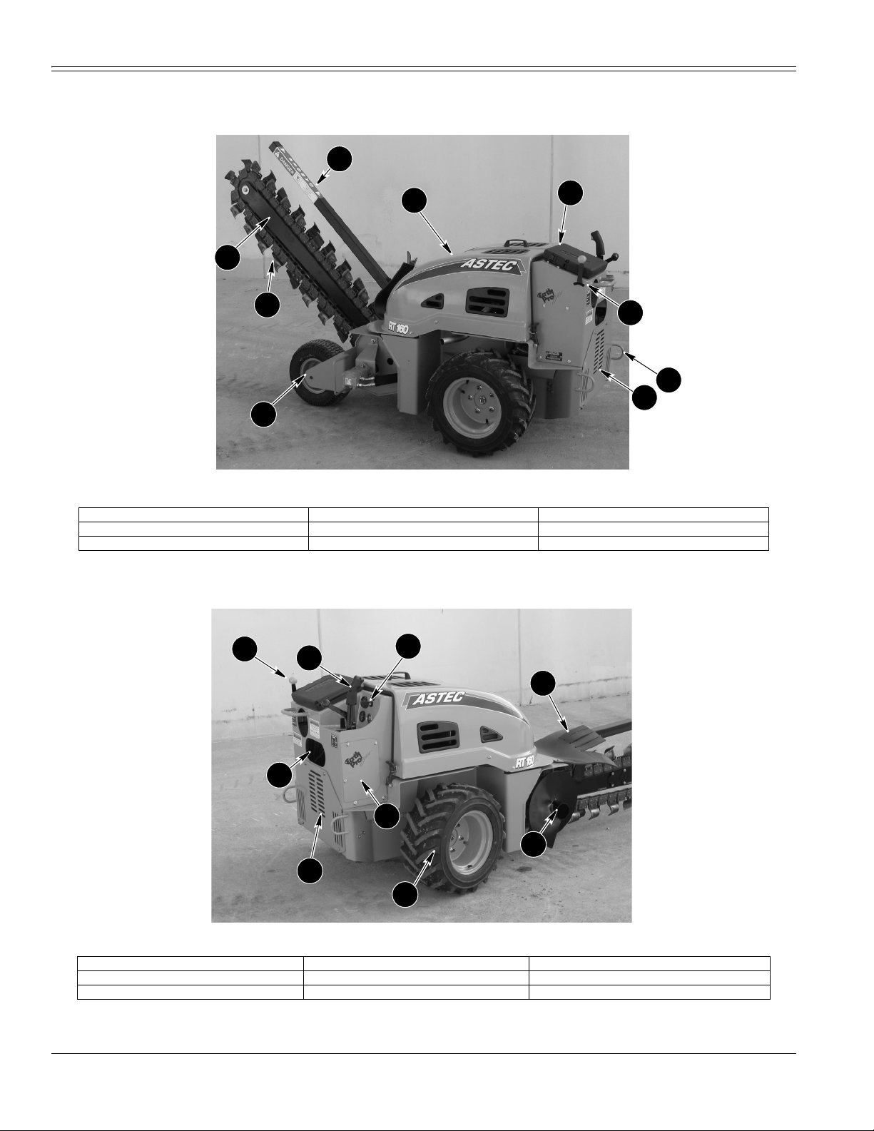
RIGHT, LEFT, FRONT AND REAR OF MACHINE . . . . . 2
IDENTIFICATION NUMBERS . . . . . . . . . . . . . . . 3
MACHINE COMPONENTS - LEFT SIDE . . . . . . . . . . . 4
MACHINE COMPONENTS - RIGHT SIDE . . . . . . . . . . 4
SAFETY/DECALS/HAND SIGNALS . . . . . . . . . . . 5
SAFETY MESSAGE . . . . . . . . . . . . . . . . . . . . . . . . . 5
PERSONAL SAFETY . . . . . . . . . . . . . . . . . . . . . . . . 5
UTILITY SAFETY . . . . . . . . . . . . . . . . . . . . . . . . . . 5
BEFORE OPERATIONS . . . . . . . . . . . . . . . . . . . . . . 6
FAILURE IN OPERATION . . . . . . . . . . . . . . . . . . . . . 7
MACHINE OPERATION . . . . . . . . . . . . . . . . . . . . . . 7
PARKING THE MACHINE . . . . . . . . . . . . . . . . . . . . . 7
CAST DUCTILE IRON . . . . . . . . . . . . . . . . . . . . . . . 7
MAINTENANCE . . . . . . . . . . . . . . . . . . . . . . . . . . . 8
BURN PREVENTION . . . . . . . . . . . . . . . . . . . . . . . . 8
PRESSURIZED HYDRAULIC FLUID AND GREASE . . . . 8
HAZARDOUS CHEMICALS . . . . . . . . . . . . . . . . . . . . 8
FIRE OR EXPLOSION PREVENTION . . . . . . . . . . . . . 9
FIRE EXTINGUISHER . . . . . . . . . . . . . . . . . . . . . . . 9
READ OPERATOR’S MANUAL . . . . . . . . . . . . . . . . . . 9
SAFETY DECALS . . . . . . . . . . . . . . . . . . . . . . . . . . 10
HAND SIGNALS . . . . . . . . . . . . . . . . . . . . . . . . . . 13
INSTRUMENTS AND CONTROLS . . . . . . . . . . . . 15
CONTROL PANEL . . . . . . . . . . . . . . . . . . . . . . . . . 15
IGNITION SWITCH . . . . . . . . . . . . . . . . . . . . . . . . 15
FUEL GAUGE . . . . . . . . . . . . . . . . . . . . . . . . . . . . 15
HOURMETER . . . . . . . . . . . . . . . . . . . . . . . . . . . . 15
AMMETER . . . . . . . . . . . . . . . . . . . . . . . . . . . . . . 15
GROUND DRIVE CONTROL . . . . . . . . . . . . . . . . . . 15
CREEP CONTROL . . . . . . . . . . . . . . . . . . . . . . . . . 16
ATTACHMENT CONTROL . . . . . . . . . . . . . . . . . . . . 16
DIGGING CHAIN / HYDRA-BORER CONTROL . . . . . 16
THROTTLE CONTROL . . . . . . . . . . . . . . . . . . . . . . 17
ENGINE CHOKE CONTROL . . . . . . . . . . . . . . . . . . 17
OPERATING INSTRUCTIONS . . . . . . . . . . . . . . 19
ENGINE OPERATION . . . . . . . . . . . . . . . . . . . . . . 19
RUN-IN MAINTENANCE SCHEDULE . . . . . . . . . . . . 19
OPERATING IN HOT WEATHER . . . . . . . . . . . . . . . 19
OPERATING IN COLD WEATHER . . . . . . . . . . . . . . 19
STARTING THE ENGINE . . . . . . . . . . . . . . . . . . . . 20
ENGINE SPEED . . . . . . . . . . . . . . . . . . . . . . . . . . 20
BOOSTER BATTERY CONNECTIONS . . . . . . . . . . . . 21
PARKING AND STOPPING THE ENGINE . . . . . . . . . 21
HYDROSTATIC BRAKES . . . . . . . . . . . . . . . . . . . . 21
MACHINE OPERATION . . . . . . . . . . . . . . . . . . . . . 21
TRENCHER OPERATION . . . . . . . . . . . . . . . . . . . . 22
TRENCHER BOOM . . . . . . . . . . . . . . . . . . . . . . . . 22
TRENCHER CHAIN AND TEETH . . . . . . . . . . . . . . . 23
BEFORE YOU OPERATE . . . . . . . . . . . . . . . . . . . . . 24
TRANSPORTING THE MACHINE ON A TRAILER . . . . 25
MOVING A DISABLED MACHINE . . . . . . . . . . . . . . 25
HYDRA-BORER OPERATION . . . . . . . . . . . . . . . . . 26
WHEELS AND TIRES . . . . . . . . . . . . . . . . . . . . 31
INSTALLING DUAL WHEELS . . . . . . . . . . . . . . . . . 33
LUBRICATION . . . . . . . . . . . . . . . . . . . . . . . . . 35
GENERAL SAFETY BEFORE SERVICING MACHINE . . 35
PLASTIC AND RESIN PARTS . . . . . . . . . . . . . . . . . 35
ENVIRONMENT . . . . . . . . . . . . . . . . . . . . . . . . . . 35
ENGINE HOURMETER . . . . . . . . . . . . . . . . . . . . . 35
CAPACITIES AND LUBRICANT SPECIFICATIONS . . . 36
LUBRICATION/MAINTENANCE CHART . . . . . . . . . . 37
ACCESS DOORS AND COVERS . . . . . . . . . . . . . . . 38
GREASE FITTINGS LOCATIONS . . . . . . . . . . . . . . 39
ENGINE LUBRICATION . . . . . . . . . . . . . . . . . . . . . 40
OIL VISCOSITY/TEMPERATURE USAGE CHART . . . 40
AIR FILTERING SYSTEM . . . . . . . . . . . . . . . . . . . . 42
FUEL SYSTEM . . . . . . . . . . . . . . . . . . . . . . . . . . . 43
HYDRAULIC OIL SYSTEM . . . . . . . . . . . . . . . . . . . 44
ADJUSTMENT/MAINTENANCE . . . . . . . . . . . . . 47
FUSE REPLACEMENT . . . . . . . . . . . . . . . . . . . . . . 47
SPARK PLUG SERVICE . . . . . . . . . . . . . . . . . . . . . 47
VALVE ADJUSTMENT . . . . . . . . . . . . . . . . . . . . . . 47
SPARK ARRESTER SERVICE . . . . . . . . . . . . . . . . . 47
DIGGING CHAIN TENSION . . . . . . . . . . . . . . . . . . 48
DECREASING CHAIN TENSION . . . . . . . . . . . . . . . 48
INCREASING CHAIN TENSION . . . . . . . . . . . . . . . 49
DIGGING CHAIN WEAR PADS . . . . . . . . . . . . . . . . 49
FIRE EXTINGUISHER . . . . . . . . . . . . . . . . . . . . . . 49
ELECTRICAL . . . . . . . . . . . . . . . . . . . . . . . . . . . 51
BATTERY . . . . . . . . . . . . . . . . . . . . . . . . . . . . . . 51
MACHINE STORAGE . . . . . . . . . . . . . . . . . . . . . 53
BOOM IDENTIFICATION . . . . . . . . . . . . . . . . . . . 55
BASIC MACHINE DIMENSIONS . . . . . . . . . . . . . . . 56
ENGINE DATA . . . . . . . . . . . . . . . . . . . . . . . . . . . 56
FUEL CAPACITY . . . . . . . . . . . . . . . . . . . . . . . . . 56
HYDRAULIC SYSTEM . . . . . . . . . . . . . . . . . . . . . . 57
SPEED . . . . . . . . . . . . . . . . . . . . . . . . . . . . . . . . 57
WHEEL DRIVE . . . . . . . . . . . . . . . . . . . . . . . . . . . 57
OPTIONS . . . . . . . . . . . . . . . . . . . . . . . . . . . . . . 57
INDEX . . . . . . . . . . . . . . . . . . . . . . . . . . . . . . . . A1

TABLE OF CONTENTS
AU104488 C6B ii

1 AU104488 C6B
TO THE OWNER
RT160 TRENCHER
RT160087, RT160091
This manual contains important information about the
safe operation, adjustment and maintenance of your
Astec Trencher. Refer to the Index at the end of this
manual for locating specific items about your machine.
This Trencher conforms to current safety regulations.
Use this manual as a guide. Your Trencher will remain a
reliable working tool as long as it is kept in good working
condition and serviced properly.
Do NOT operate or permit anyone to operate or
service this machine until you or the other persons
have read and understand the safety, operation
and maintenance instructions in this manual. Use
only trained operators who have demonstrated the
ability to operate and service this machine
correctly and safely.
This Trencher, with standard equipment and authorized
attachments, is intended to be used for general earth
moving purposes, handling, ditch digging, etc. Make sure
that the machine is properly equipped and follow the
instructions and safety precautions in this manual.
Do Not use this machine for any application or
purpose other than those described in this manual.
Consult an authorized Astec dealer on changes, additions
or modifications that can be required for this machine to
comply with various country regulations and safety
requirements. Unauthorized modifications will cause
serious injury or death. Anyone making such unauthorized
modifications is responsible for the consequences.
This Operator’s Manual is to be stored in the manual
compartment equipped on this machine. Make sure this
manual is complete and in good condition. Contact your
dealer to obtain additional manuals. Contact your dealer
for any further information or assistance about your
machine. Your dealer has Astec-approved service parts.
Your dealer has technicians with special training that
know the best methods of repair and maintenance for
your Trencher.
RT160073
AFTER DELIVERY CHECK
Two copies of the After Delivery Check are in the back of
this manual. One copy is for you and one copy is for the
dealer. Make sure that your dealer does the After Delivery
Check after the first 50 hours of machine operation.
Your cost for this inspection will be for filters, oil and/or
other accessories. If the dealer comes to your machine,
there can also be a cost for the time and distance
traveled.
Operator’s Manual Storage

TO THE OWNER
AU104488 C6B 2
RIGHT, LEFT, FRONT AND REAR OF MACHINE
Right-hand and left-hand, when used in this manual, indicate the right and left sides of the machine as seen from the
operators position facing the machine engine and operating the controls.
RT160086, RT160090
VIEWED FROM RIGHT SIDE
FORWARD REARWARDDIRECTION OF TRAVEL
VIEWED FROM LEFT SIDE
REARWARD FORWARDDIRECTION OF TRAVEL

3 AU104488 C6B
IDENTIFICATION NUMBERS
Write your machine Product Identification Number (P.I.N.) and Serial Numbers on the lines provided below. If needed,
give these numbers to your dealer when requesting parts or information for your machine.
Make a record of the numbers. Keep the record and your Manufacturer’s Statement of Origin in a safe place. If the
machine is stolen, report the numbers to your local law enforcement agency.
MACHINE MODEL NUMBER: RT160 Trencher
1. PRODUCT IDENTIFICATION NUMBER (P.I.N.) ________________________________________________________
2. ENGINE SERIAL NUMBER ________________________________________________________
RT160014
1. PRODUCT IDENTIFICATION NUMBER RT160049
2. ENGINE SERIAL NUMBER
1

IDENTIFICATION NUMBER
AU104488 C6B 4
MACHINE COMPONENTS - LEFT SIDE
RT160091
MACHINE COMPONENTS - RIGHT SIDE
RT160085
2
4
6
1
9
5
8
7
3
1. RESTRAINT BAR 4. DIGGING CHAIN CONTROL 7. TRENCHER BOOM
2. ENGINE HOOD 5. DIGGING CHAIN 8. REAR TIE DOWNS
3. GUIDE WHEEL 6. OPERATORS MANUAL STORAGE 9. HYDRAULICS ACCESS COVER
4
6
9
1
5
7
8
3
2
1. DIGGING CHAIN GUARD 4. AUGER 7. GAUGES
2. DIGGING CHAIN CONTROL 5. RIGHT ACCESS AREA 8. GROUND DRIVE CONTROL
3. ENGINE CONTROLS ACCESS 6. DRIVE WHEEL 9. HYDRAULICS ACCESS COVER

5 AU104488 C6B
SAFETY/DECALS/HAND SIGNALS
SAFETY MESSAGE
This machine has been designed and built to meet or
exceed current safety regulations and standards.
However, this does not completely exclude the risk of
accidents. It is therefore essential to follow basic safety
rules and procedures.
The strict execution of the instructions provided in this
manual will help prevent accidents during machine use,
maintenance and repair operations.
These instructions will only be effective if the machine
receives proper maintenance. Any defects or
abnormalities must be repaired immediately.
Do not use the machine for applications other than those
which are described in this manual.
In the event of a particular problem, requiring some
intervention or application not described in this manual,
contact your Astec dealer immediately.
Most accidents involving machine operation and
maintenance can be avoided by following basic rules and
precautions. Read and understand all the safety
messages in this manual, and the safety signs on the
machine before you operate or service the machine. See
your Astec dealer if you have any questions.
READ THIS MANUAL COMPLETELY and make sure you
understand the characteristics of speed, stability, and
steering of this machine. The machine must be used only
by trained operators. KEEP THE OPERATOR’S MANUAL IN
THE STORAGE BOX provided and make sure it is always
fastened to the machine, in complete and good condition.
See your dealer for additional manuals. Also see the
inside of the rear cover of this manual.
RT160073
OPERATOR’S MANUAL STORAGE
The safety information given in this manual does not
replace safety codes, insurance regulations, or local laws.
Make sure your machine has the correct equipment
according to these rules or laws.
IMPORTANT:
Safety messages in this section point out
situations which can be encountered during the normal
operation and maintenance of your machine. These safety
messages also give possible ways of dealing with these
conditions. Additional safety messages are used in the
text of the manual to show specific safety hazards.
PERSONAL SAFETY
Safety Decals on this machine use the words Danger,
Warning or Caution, which are defined as follows:
•DANGER:Indicates an immediate
hazardous situation which, if not avoided,
will result in death or serious injury. The color associated
with Danger is RED.
• WARNING: Indicates a potentially
hazardous situation which, if not avoided
will result in serious injury. The color associated with
Warning is ORANGE.
• CAUTION: Indicates a potentially
hazardous situation which, if not avoided,
may result in minor or moderate injury. It may also be
used to alert against unsafe practices. The color
associated with Caution is YELLOW.
ISO two panel pictorial symbol decals are shown in both
vertical and horizontal configurations and are defined as
follows:
•The Signal panel indicates the nature of the hazard.
•The Message panel indicates the appropriate avoidance
of the hazard.
•Background color is YELLOW.
•Prohibition symbols such as and if
used are RED.
UTILITY SAFETY
Safety precautions MUST be followed when working near
buried utility lines
During operation it is likely that you will be working
around or near buried utility lines which may include, but
are not limited to:
•Electrical Power Line
•Gas Line
•Water Line
•Communication Line - Telephone or Cable Television
•Sewer Line
STOP

SAFETY
AU104488 C6B 6
Before beginning any trenching, drilling or other
construction work it is your responsibility to be
aware of all such utility lines buried in the area of
your project and to avoid them.
ALWAYS have all local utility companies mark the location
of their lines.
In U.S.A. and Canada call one of many “One Call System
Directory” services. If you do not know the local number,
call the national number (U.S.A. and Canada only): 1-888-
258-0808.
Check with local authorities for laws, regulations
and/or strict penalties requiring you to locate and
avoid existing utilities.
RH99G001
CALL ALL LOCAL UTILITY COMPANIES BEFORE YOU TRENCH
Know the utility color code (U.S.A. and Canada):
Electric .......................................................... Red
Gas, Oil or Petroleum.................................. Yellow
Communication, Telephone, Television ........ Orange
Water ................................................. ..........Blue
Sewer.............................................. Green/Brown
Proposed Excavation.................................... White
Surveying ..................................................... Pink
Reclaimed Water and Slurry ........................ Purple
After locating the utility lines, carefully dig a hole by hand
and/or automatic vacuum equipment to the utility line to
verify the location and depth of the line.
BEFORE OPERATIONS
•Avoid loose fitting clothing, loose or uncovered long
hair, jewelry and loose personal articles.
•Different jobs may require different protective
equipment. Items such as hard hats, protective shoes,
heavy gloves, reflector type vests, respirators and ear
protection may be required. Know and use the
equipment that is required before you start the job.
•Be prepared for emergencies. Always have a first aid
kit and a good fire extinguisher close by and know how
to use each.
•Know the hand signals used on your job. Follow the
instructions of the flagman, signs, etc. See Hand
Signals in this manual.
•Check that all guards, covers and safety decals are
installed correctly or closed. NEVER operate the
machine without guards in place.
•Foreign material such as ice or grease on the controls
or handlebar can cause an accident. Keep these areas
clean.
•Remove all loose objects from operators area and from
the machine. Loose objects can jam controls and cause
accidents.
•Make sure all persons are away from the machine
before you start the engine.
•Always face the machine when using the machine. Do
not rush.
•Before you start each day, walk around the machine
and check for oil or fluid leaks. Replace all broken,
loose, worn or missing parts and do the required
lubrication and maintenance as shown in this manual.
•Engine exhaust fumes can cause death. If you operate
this machine in an enclosed area, use good ventilation
to replace the exhaust fumes with fresh air.
•Know the rules, laws and safety equipment necessary
for transporting this machine on a road or highway.
Rotating beacon, backup alarm, SMV and other safety
equipment items are available from you dealer.
•Make sure the parking brake is engaged and that all
controls are in neutral before starting the engine.
WARNING:
Always contact your local One-
Call system and any utility companies which
do not subscribe to One-Call before the start
of your digging project.

SAFETY
7 AU104488 C6B
FAILURE IN OPERATION
•In the event of poor performance or machine failure,
stop the machine immediately and report the matter.
Take measures to prevent further use until the
malfunction is corrected (Place a DO NOT OPERATE
tag on the control panel, remove the key, turn off all
power sources, etc.) Before working on any hydraulic
or electrical circuits, refer to the maintenance sections
in this manual.
•Support or lower all attachments to the ground before
leaving or servicing the vehicle.
MACHINE OPERATION
•Check all controls in a clear area and make sure the
machine is operating correctly.
•Dust, fog, smoke, snow, etc., may decrease your vision
and cause an accident. Stop the machine or decrease
the speed until you can see everything around you in
the work area.
•Contact with high voltage power lines, underground
cables, etc., can cause serious injury or death from
electrocution.
•Before you operate in an area with high voltage lines or
cables, contact your utility companies or one of the
Digging Hot Line numbers. You MUST HAVE THE
POWER DISCONNECTED OR KEEP A SAFE
WORKING DISTANCE from the lines or cables. You
must know the safe working distance from the high
voltage power equipment and must know any federal,
state/provincial or local safety codes or regulations that
apply to the job site.
•Electrical cables, gas pipes, water pipes or other
underground objects can cause injury or death. Learn
the location of underground hazards before you
operate your machine in a new area.
•If this machine turns over, you can be injured or killed.
Do not operate if weather, road or earth conditions will
not permit safe operation on a hill, ramp, or rough
ground.
•Stay away from hazardous areas such as ditches,
overhangs, etc. Walk around the work area before you
start and look for hazards.
•Be alert and always know the locations of all workers in
your area. Keep all other persons completely away
from your machine. Injury or death can result if you do
not follow these instructions.
•If your view of the work area is not clear, always have
a signal person direct your movement. Know and
understand each signal from the signal person before
you start.
•Operate the machine controls from the operators
position only.
•DO NOT operate this machine while under the
influence of alcohol or drugs.
• NEVER allow anyone in the trench while digging.
PARKING THE MACHINE
•When you park the machine, select level ground
whenever possible. If you must park on a slope or
incline, position the machine at right angles to the
slope.
•Before you leave the operators area, always support or
lower all attachments to the ground, apply the parking
brake, stop the engine and remove the key.
•Follow the instructions in this manual for parking the
machine.
CAST DUCTILE IRON
•Before you weld, cut or drill holes in a part on this
machine, make sure the part is not cast ductile iron.
See your dealer if you do not know if a part is cast
ductile iron.
•Unauthorized modifications to cast ductile iron parts
can cause injury or death. Welding, cutting or drilling
can cause cast ductile iron to break. Do not weld, cut
or drill to repair or to attach items to cast ductile iron
parts on this machine.
WARNING:
Shut off engine and remove key
before performing any maintenance or repair
work.

SAFETY
AU104488 C6B 8
MAINTENANCE
•Before you service the machine, park on a level
surface.
•Before you service the machine, put a Do Not Operate
tag on the control panel. A Do Not Operate tag (Part
Number AU103157) is included with each new
machine. Extra tags are available from your dealer.
PIC00056
•Improper service or repair can cause injury or death. If
you do not understand a service or adjustment
procedure, see the Service Manual for this machine or
see your dealer.
•Unauthorized modifications to this machine can cause
injury or death. Do not make unauthorized
modifications to this machine. Always see your dealer
before you weld, cut or drill holes in your machine.
•When you service this machine, always wear face or
eye protection, safety shoes and other protective items
as required.
•If you must service this machine with the engine
running, have another person help you. Follow the
instructions in this manual.
•Metal chips or debris can cause eye injury. Always wear
eye or face protection especially when you use a
hammer on this machine. Use a hammer with a soft
face, such as brass, to drive hardened pins.
•When you replace parts on your machine, always use
Astec parts. See your dealer.
•If you must service the machine with an attachment
raised, always block up the attachment.
•To prevent accidental movement of the machine,
always block the tires before you service the machine.
BURN PREVENTION
•Battery acid causes severe burns. Batteries contain
sulfuric acid. Avoid contact with skin, eyes, or clothing.
Antidote - EXTERNAL: Flush with water. INTERNAL:
Drink large quantities of water or milk. Follow with milk
of magnesia, beaten egg or vegetable oil. Call a doctor
immediately. EYES: Flush with water for 15 minutes
and get prompt medical attention.
•When the battery electrolyte is frozen, the battery can
explode if, (1) you try to charge the battery, or (2) you
try to jump start and run the engine. To prevent the
battery electrolyte from freezing, try to keep the
battery at full charge. If you do not follow these
instructions, you or others in the area can be injured.
PRESSURIZED HYDRAULIC
FLUID AND GREASE
•Hydraulic fluid or grease injected into your skin can
cause severe injury or death. Keep your hands and
body away from any pressurized leak. If fluid is
injected into your skin, get medical attention
immediately and have the fluid removed.
HAZARDOUS CHEMICALS
•If you are exposed to or come in contact with
hazardous chemicals you can be seriously injured. The
fluids, lubricants, paints, adhesives, coolants, etc.,
used with your machine can be hazardous.
•Material Safety Data Sheets (MSDS) provide
information about the chemical substances within a
product, safe handling procedures, first aid measures
and procedures to be taken when the product is
accidentally spilled or released. MSDS are available
from your dealer.
WARNING:
Battery acid may cause burns.
Avoid contact.
WARNING:
Fluid under pressure can pierce
skin and cause injury or death. Stay away.
WARNING:
Improper handling or use of
chemicals may result in illness, injury, or
equipment damage. Follow instructions on
labels and in material safety data sheets
(MSDS).

SAFETY
9 AU104488 C6B
•Before you service your machine, check the MSDS for
each fluid, lubricant, etc., used in this machine. This
information indicates what the risks are and how to
service the machine safely. Follow this information
when servicing the machine.
•Before you service this machine and before you
dispose of the old fluids and lubricants, always
remember the environment. DO NOT put oil or fluids
into the ground or into containers that can leak.
•Check with your local environmental or recycling center
or your dealer for correct disposal information.
FIRE OR EXPLOSION
PREVENTION
•Engine fuel can cause an explosion or fire. Do not fill
the fuel tank with the engine running, if you are near
an open fire, or if you are welding, smoking, etc.
•Use nonflammable cleaning solvent to clean parts.
•Sparks or flame can cause the hydrogen gas in a
battery to explode. To prevent an explosion, do the
following:
1. When disconnecting the battery cables, disconnect
the negative (-) cable first; when connecting the
battery cables, connect the negative (-) cable last.
2. When connecting jumper cables to start the engine,
use the procedure shown in this manual. See Booster
Battery Connections in this manual.
3. Do not short circuit the battery posts with metal
items.
4. Do not weld, grind, or smoke near a battery.
•Sparks from the electrical system or engine exhaust
can cause an explosion and fire. Before you operate
this machine in an area with flammable dust or vapors,
use good ventilation to remove the flammable dust or
vapors before you start.
•Remove all trash or debris from the machine. Make
sure that oily rags or other flammable materials are not
stored on the machine.
•A fire can cause injury or death. Always have a fire
extinguisher close by. Make sure the fire extinguisher is
serviced according to the manufacturers instructions.
•Check for fuel, oil, and hydraulic fluid leaks. Replace
worn or damaged hoses or lines. After repairs are
made, clean the machine before you operate.
FIRE EXTINGUISHER
Type of Fire Extinguisher
It is recommended that you have a fire extinguisher close
by. The fire extinguisher of the type shown is available
from your dealer.
153L95
READ OPERATOR’S MANUAL
Decals which display the “Read Operators Manual” symbol
are intended to direct the operator to the Operators
Manual for further information regarding safety,
maintenance, adjustments and/or procedures for specific
areas of the machine. When a decal displays the following
symbol refer to the Operators Manual.
237187A1
“READ OPERATORS MANUAL”
WARNING:
Fire or explosion possible.
Fumes could ignite and cause burns. No
smoking, no flame, no spark.

SAFETY
AU104488 C6B 10
SAFETY DECALS
•Make sure that you read all safety and instruction
decals. Check these decals every day before you start.
Clean these decals if you cannot read the words.
•When you clean the decals, use only a cloth, water and
mild soap. Do not use solvent, gasoline, etc.
•You must replace a decal if the decal is damaged,
missing or cannot be read.
•If a decal is on a part that is replaced, make sure you
install a new decal on the new part. See your dealer for
new decals.
RT160078
H438699
1. This decal is located on the machine near the gasoline
fill tube.
RT160016
321-3213
2. This decal is located on the side of the engine
compartment opposite the fuel tank.
RT160081
321-6714
3. This decal is located near the battery, in the front
engine access area.
ATTENTION:
Injury or death can result if you
cannot read a safety decal or if a safety decal is
missing. Replace any missing or damaged safety
decal and keep all safety decals clean. See your
Astec dealer for new safety decals.
1
1
2
2
3
3

SAFETY
11 AU104488 C6B
RT160081
AU103971
4. This decal is located in the engine compartment by
the hydraulic reservoir.
RT160016
H438698
5. This decal is located in the engine compartment near
the exhaust muffler.
283607A1, RT160145 AND RT160019
6. This decal is located near the front tire. If equipped
with Hydra-borer, this decal is also located on the
hydra-borer shield.
RT160001, H438909, AND H438910
7. This decal is located on both sides of the trencher
restraint bar.
8. The DANGER decal is located on the top surface of
the restraint bar.
4
4
5
5
6
6
87
7
8

SAFETY
AU104488 C6B 12
RT160074
384267A1
9. This decal is located by the control panel.
RT160073
321-3214
10. This decal is located near the control panel.
RT160092
AU103976
11. The Hot Surfaces decal is found on the engine access
covers.
RT160077
12. Tie Downs
94F25
IMPORTANT:
Tie downs are not to be used for towing.
9
9
10
10
11
11
12
TIE DOWN
12

SAFETY
13 AU104488 C6B
HAND SIGNALS
It is recommended that you and the flagman on the job use hand signals for communications. Before you start, make
sure that you both understand the signals that will be used.
PDE0003A
COME TO ME
PDE0005A
STOP
PDE0002A
START ENGINE
PDE0002
STOP ENGINE
PDE0003
MOVE AWAY FROM ME
PDE0004
ALL STOP AND HOLD
PDE0006A
RAISE LOAD
PDE0006
LOWER LOAD
PDE0004A
GO THIS FAR
PDE0005
EMERGENCY STOP
PDE0007A
RAISE LOAD SLOWLY
PDE0007
LOWER LOAD SLOWLY

SAFETY
AU104488 C6B 14
NOTES

15 AU104488 C6B
INSTRUMENTS AND CONTROLS
CONTROL PANEL
RT160073
1. IGNITION SWITCH
2. FUEL GAUGE
3. HOURMETER
4. AMMETER
5. OPERATOR PRESENCE TRIGGER
6. GROUND DRIVE CONTROL
7. CREEP CONTROL
8. ATTACHMENT CONTROL
9. DIGGING CHAIN / HYDRA-BORER CONTROL
228193
IGNITION SWITCH
The ignition switch (1) has the following positions:
A. OFF - Use this position to stop the engine, deenergize
the electrical system and to remove the key.
B.ON - This position will energize the electrical system.
The key will return to this position after you release
the key from START.
C. START - Turn the key to this position to engage the
starter motor to start the engine.
NOTE:
The ground drive control must be in the NEUTRAL
position and the digging chain control must be released
before you can start the engine
.
NOTE:
See STARTING THE ENGINE in this manual for the
correct procedure to start the engine.
FUEL GAUGE
The fuel gauge (2) indicates the amount of fuel in the fuel
tank.
HOURMETER
The hourmeter (3) indicates the total hours of operation
in hours and tenths of an hour. Use the hourmeter to
measure the time between machine service intervals.
AMMETER
The ammeter (4) shows the rate of charge or discharge of
the battery. When the needle is to the right of 0, the
battery is being charged. If the needle is to the left of 0
during normal engine operation, the battery is
discharging. Stop the engine and check for a problem in
the charging system.
GROUND DRIVE CONTROL
The trigger (5) activated joystick (6) has five positions;
FORWARD, NEUTRAL, REVERSE, RIGHT and LEFT. The
joystick must be in the NEUTRAL position before you can
start the engine. Use this joystick to control the direction
and speed of the machine. The machine will move in the
direction you move the joystick. The farther you push or
pull the joystick, the faster the machine will move. Move
the joystick to the NEUTRAL position to stop the machine.
The joystick will return to the NEUTRAL position when you
release the joystick.
From the NEUTRAL position, pull the joystick slightly
FORWARD (toward you) for forward ground travel. Pull
the joystick further to increase the forward ground speed.
Push the joystick slightly rearward to decrease the
forward ground speed.
6
7
1
2
4
3
8
9
5

INSTRUMENTS/CONTROLS
AU104488 C6B 16
From the NEUTRAL position, push the joystick slightly
REARWARD (away from you) for reverse ground travel.
Push the joystick further to increase the reverse ground
speed. Pull the joystick slightly forward to decrease the
reverse ground speed.
While moving push the joystick slightly LEFT or RIGHT to
turn. The joystick is spring loaded left-to-right and will
return to the center position.
Engine speed is controlled by the Throttle Control on the
engine. Refer to THROTTLE CONTROL in this manual.
FORWARD - Pull the joystick forward (toward you).
REVERSE - Push the joystick to the rear (away from you).
NEUTRAL - Release the joystick.
RIGHT - Push the joystick to the right.
LEFT - Push the joystick to the left.
ATTENTION:
When you release the trigger, all
movement stops abruptly. The engine will continue to
run. The joystick must be returned to NEUTRAL before
operation can continue.
NOTE:
You cannot use the FORWARD/REVERSE positions
if you are using the Creep Control Lever, but the RIGHT/
LEFT positions will steer the machine.
CREEP CONTROL
The creep control lever (7) has three positions;
FORWARD, NEUTRAL, and REVERSE. Use this lever to
control the forward/reverse direction and machine speed
during machine operation. The machine will move in the
direction that you move the lever. The farther you push or
pull the lever, the faster the machine will move. The lever
will lock in position when you release the lever.
FORWARD - Pull the lever forward (toward you).
REVERSE - Push the lever to the rear (away from you).
ATTACHMENT CONTROL
The attachment control lever (8) has two positions, RAISE
and LOWER. Use this lever to raise or lower the trencher
boom. Pull the control toward you to raise the trencher
boom. Push the lever away from you to lower the
trencher boom.
DIGGING CHAIN / HYDRA-BORER CONTROL
When the machine is equipped with Hydra-borer, the
mode (TRENCH or BORE) is selected by the valve control
lever (10) near the hydra-borer and trencher motor.
Pull the control lever (10) out to operate the trencher.
Push the control lever (10) in to operate the hydra-borer.
RT160145
Once the mode is selected, the Digging Chain / Hydra-
borer control lever (9) is used to control the action.
RT160146
When in the TRENCH mode, push the lever (9) away from
you to engage the digging chain. Pull the lever back to
you to stop the chain.
When in the BORE mode, push the lever away from you
to the BORE position to rotate the hydra-borer shaft
clockwise. Pull the lever back to you to the REVERSE
position to rotate the hydra-borer shaft counterclockwise
WARNING:
You MUST pull the trigger
control on the joystick before you can move
the machine.
WARNING:
The operator presence/trigger
interlock system provides protection from
injury. Do not disable or bypass the system.
10
9
This manual suits for next models
1
Table of contents
Other ASTEC Lawn And Garden Equipment manuals