CRAM-A-LOT VB-42-B Specifications
“Equipping The World For A Better Environment”
MODELS
VB-42-B
VB-42-B-LP
VB-60-B
VB-60-B-LP
VB-60-T
VB-60-H
VB-60-X
VB-60-H-DC
VB-60-H-LP
VB-72-B
VB-72-B-LP
VB-72-T
VB-72-H
VB-72-X
VB-72-H-DC
VB-72-H-LP
Operation, Maintenance, and Installation
OWNER / OPERATOR INSTRUCTION MANUAL

2

3
Congratulations
You have just purchased a quality designed and manufactured CRAM-A-LOT® Baler.
Manufacturing balers and compactors since 1978, J.V. Manufacturing offers quality workmanship, factory trained installa-
tion and a national service network. Advanced features have been designed into the Baler for modern waste disposal
operations.
As with any investment, a return is expected, and the return received from this investment will be in the form of maximum
performance during many years of dependable service.
In order to maintain quality performance and safe operation of your new baler, it is necessary to observe and practice the
operation and maintenance information provided in this manual.
The employer involved in the operation, maintenance, and installation of the baler should read and understand the most
current version of the following applicable standards.
ANSI Standard No. Z245.5, “Baler-Safety Requirements for Installation, Maintenance and Operation”.
A copy of this standard may be obtained from:
ENVIRONMENTAL INDUSTRIES ASSOCIATION
4301 Connecticut Avenue, NW
Washington D.C. 20008
Website http://www.wastec.org
If, after thoroughly reading this manual, there are questions about the operation or repair of your baler, please contact
J.V. Manufacturing, Inc., and our Customer Support Team will provide assistance.
CRAM-A-LOT® Customer Support
Tel: 800-754-4290
Fax: 479-751-7870
Hours: 7:00 am - 5:00 pm CST®
Monday - Friday
JV Manufacturing Corporate Philosophy
It is the stated goals of J.V. Manufacturing, Inc. to build equipment of uncompromising quality, provide the absolute best
customer service in our industry, and to conduct all business with honesty and integrity, whether it be with customers,
vendors, fellow employees or members of the community.
J.V. Manufacturing, Inc. encourages positive change. Change will provide opportunities for future growth and new direc-
tions as we move into the future.

4

5
Introduction 5
Troubleshooting 19-20
Warranty Policy & Procedures 30-32
Baler Operation 8-13
Maintenance 14-18
Responsibilities of the Owner / Operator.………………………………………………………………………………..………………..8
Safety Orientation……………...………….…………………………………………………………………………… …………………………….9
Controls…...……………….………………………………………………………………………………………………………………………...…….10
Emergency Operation…………………………………………………………………………………………………….………………………...11
Baler Operation……...…………….………………………………………………………………………………….……………………………….11
Making & Tying a Bale…………………………………………………………………………………………………………………………..….11
Making & Tying a Bale with Front Feed Wire Guide Option…………………………………………………………………….12
Ejecting a Bale……….…………….…………………………………………………………………………………..…………………………...….12
Bale Tie Configuration……………………………………...…...………………………………………………………………………….…….13
Lockout & Tagout Procedures……….……………….……………………………………………………………...………………………...14
Chocking the Presshead………………………………….………………………………………………………………………………………..15
Preventive Maintenance Schedule...……………….………………………………………………………………………………………..16
Decal Locations & Ordering Information……..….……………………………….…………………………………………………..….17
Checking and Adding Oil…………………………………………………………………………………………………………………..……..18
Table of Contents
Parts Diagrams 23-27
Chassis , Loading Door....……………………………………………………………………………………………………………….….…23-24
Power Unit ……...……………………………………………………………………………………………………………………...…………...…..25
Hydraulic Tank ……...………………………………………………………………………………………………………………………..……....26
Control Panel ……..…………………………………………………………………………………………………………………………………...27
Installation Guidelines 6-7
Positioning.……….……………...………….……………………………………..………………………………..……………………………...… ..6
Anchoring.……………….……………………………………………………………..……………………………………………………….…...…...7
Electrical……………………………………………………………………………………..………………………….…….……………………….…...7
Hydraulic………………………………………………………………………………………..……………………….……………………………....…7
Schematics 28-29
Electrical Schematic…...……..………….…………………………………………………………………………………………..………….…..28
Hydraulic Schematics..………………………………………………………………………………………………….…………………………..29
Technical Specifications 21-22
5
Manual0025 Rev. K. Effective 04-07-16
6
REQUIRED FLOOR SPACE
Your CRAM-A-LOT® Vertical Baler requires up to 132 square feet of clear floor space for proper installation and
operation. (11' x 12') This space should always be kept clear of materials which could interfere with the safe
operation of the baler. WARNING: Foreign objects can fall into the bale chamber between the rear supports of the
baler, wedge under the presshead and turn the baler over onto its front. Damage to the baler and personal injury
can result. ALWAYS keep this area clean.
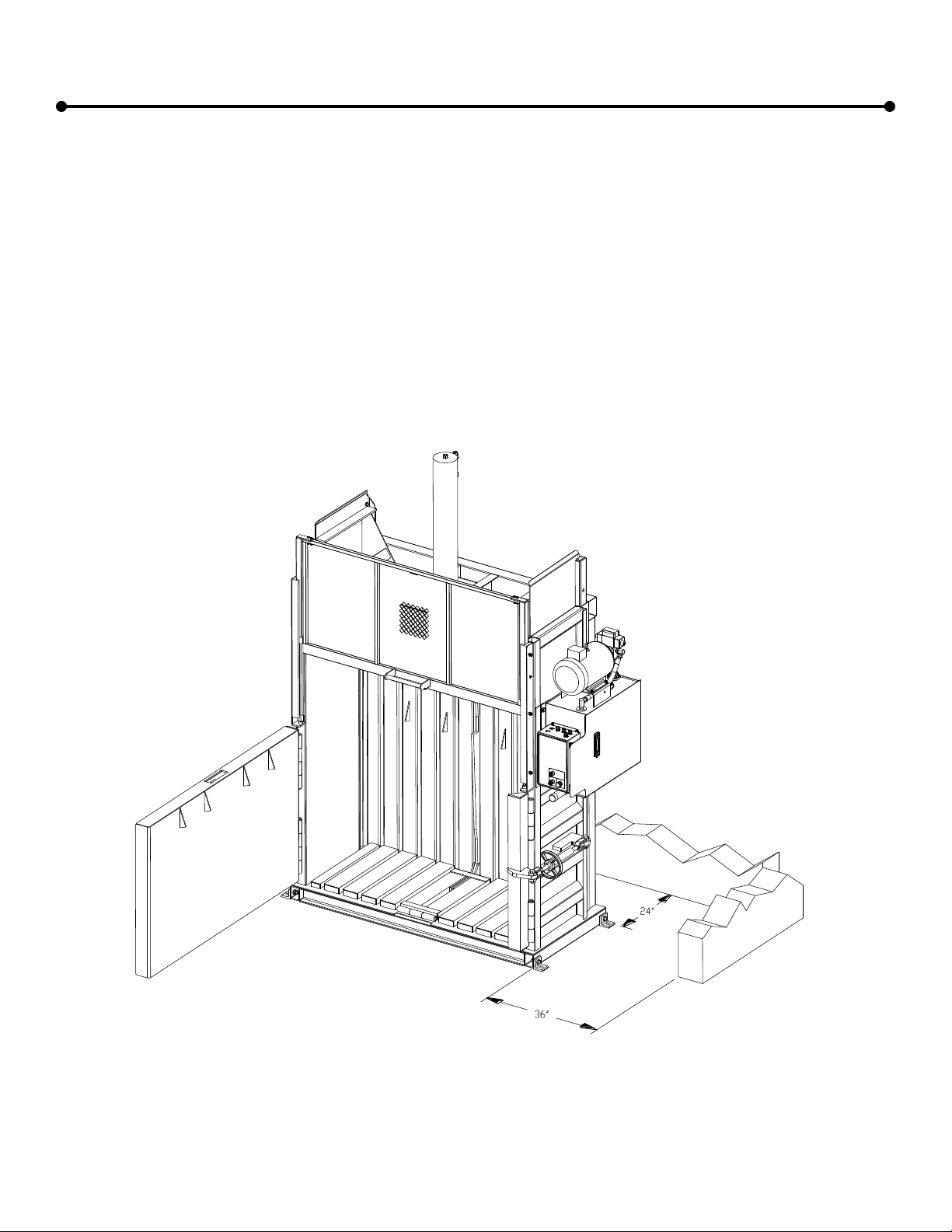
POSITIONING
Position the vertical baler indoors or under a suitable cover so that sufficient room is available for proper and
safe operation. The baler should be placed no less than 24 inches from any structure to allow room to insert wires
and tie off the bale. The power unit side of the baler should be placed no less than 36 inches from any structure to
allow room to open the chamber door and access the back of the unit. Adequate room must also be present in front
of the baler to allow the chamber door to swing fully open so the finished and tied bale can be ejected.
Installation Guidelines
Fig. 1
7
Installation Guidelines, cont.
ANCHORING
The recommended mounting surface for the baler is a pad of steel reinforced concrete with a minimum 3,000 psi
capacity. The pad should be at least 4 inches deep. The baler should be anchored using the anchor pads provided
with the machine. The anchor pads should be fastened to the baler footer using the supplied hardware. Secure the
anchor pads to the mounting surface with 4 anchor bolts (minimum 3/8"x4"). To allow for construction variances, the
holes should be drilled after locating the baler in the desired position.
ELECTRICAL
A lockable fused disconnect switch (customer furnished) must be installed within 50 feet, and in line of sight of
the baler electrical enclosure. This disconnect must be sized in accordance with the baler motor and voltage.
GROUNDING INSTRUCTIONS
This appliance must be connected to a grounded, metal, permanent wiring system; or an equipment-grounding
conductor must be run with the circuit conductors and connected to the equipment-grounding terminal or lead on the
appliance. A qualified electrician should be consulted if there is any doubt as to whether an outlet box is properly
grounded.
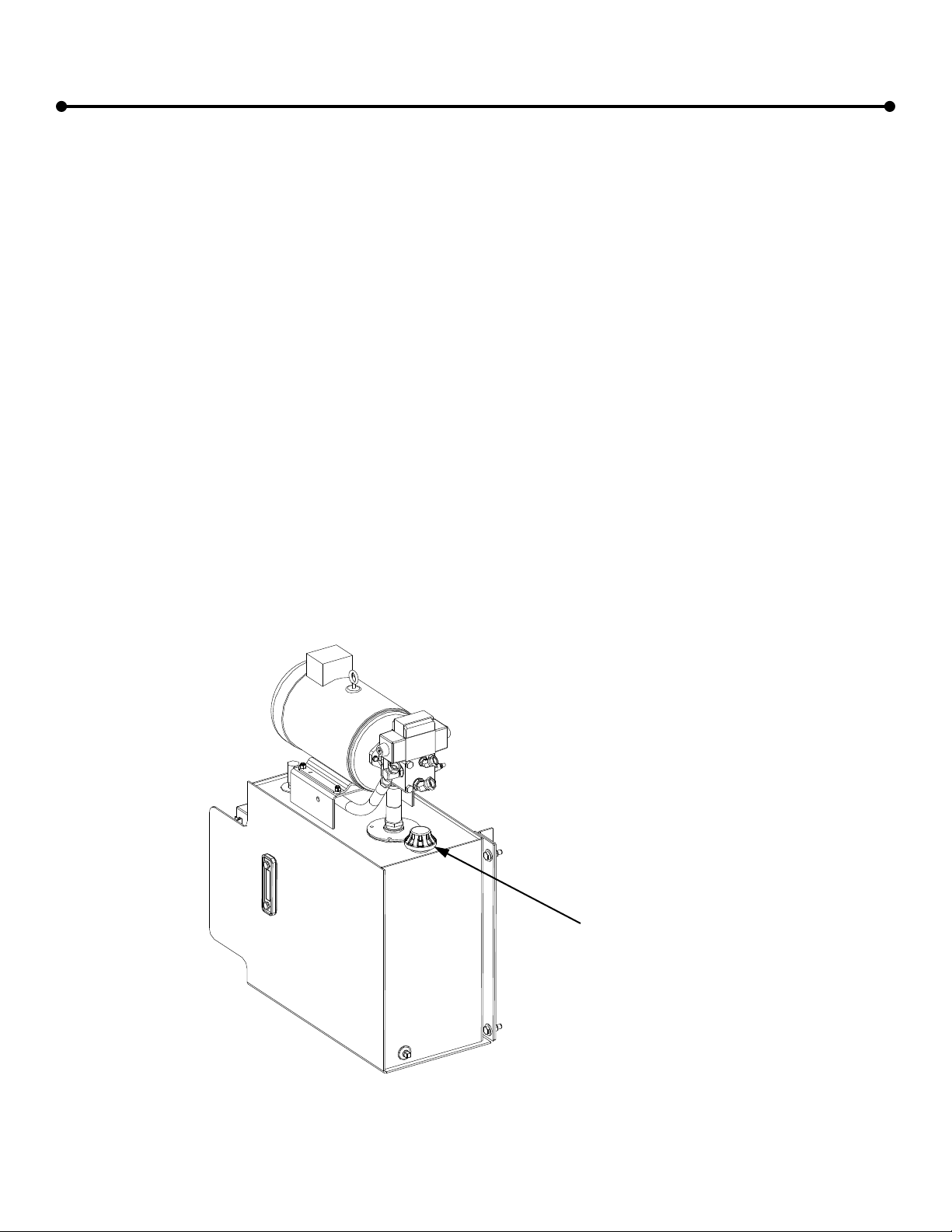
HYDRAULIC
Install the included vented cap on the hydraulic tank before operating the machine.
Ensure that vented cap is installed
before running machine.
Fig. 2

8
Baler Operation
ANSI Guidelines
Responsibilities of the Owner / Employer
The employer / owner shall ensure that the vertical baler is properly maintained and meets all applicable regulatory standards
and shall be responsible for the following:
1. Ensuring that the installation of the equipment conforms with all local codes, ordinances, and manufacturer’s recommenda-
tions.
2. Providing instruction and training to employees on safe work methods, including procedures provided by the manufacturer,
before assigning them to operate, clean, service, maintain, modify, or repair the equipment. The owner / employer will main-
tain records as to the names of employees and the dates of training.
3. Monitoring the user’s / employee’s operation of the baler and taking appropriate action to ensure proper use of the equipment
including adherence to safe practices.
4. Repairing any mechanical malfunctions or breakdowns that affect the safe operation of the baler.
5. Establishing and following a program of periodic and regular inspections of the equipment to ensure that all parts, component
equipment, and safeguards are in safe operating condition, and adjusted, in accordance with the manufacturer’s recommend-
ed procedures. This shall include keeping all malfunction reports and record inspections and maintenance work performed.
6. Using the manufacturer’s recommended procedures for the lockout/tagout of hazardous energy sources. (See OSHA 29 CFR
1910.147, Appendix A, for recommended lockout/tagout procedures.)
7. Providing for an adequate work area around the equipment for safe maintenance, servicing, and cleaning procedures (see
OSHA 29 CFR 1910.303 for electrical equipment).
8. Keeping all surrounding walking areas and floors free from obstructions, and accumulations of waste matter, grease, oil, and
water.
9. Maintaining records or employee reports of malfunctions.
10. Specifically inspecting safety interlocks, switches, and other protective devices to ensure that these devices are not disabled
or bypassed, and not to permit the equipment to be operated unless these devices are fully functional. These inspections
shall be in accordance with item 5.
11. Ensuring that only authorized employees (18 years old or older) operate, inspect, or maintain the equipment.
Responsibilities of the Operator / Employee
The operators / employees who work on and around the vertical baler shall be responsible for the items listed below:
1. Using all applicable safety features provided on the equipment.
2. Using the equipment only after receiving instruction.
3. Reporting any damage to, or malfunction of, the equipment by submitting a report to the employer or responsible authority
when the damage or malfunction occurs.
4. Ensuring that all access doors and service opening covers are in place, secure, and/or locked before operations begin.
5. Ensuring that the area of operation around the baler is clear of all persons during all phases of the dumping operation prior to
energizing the dumping system.
6. Ensuring that all persons are clear of the equipment point of operation before actuating any compaction cycle controls or
dumping controls and shall be ready to stop the compaction cycle or dumping operation if necessary.
7. Ensuring that all persons are clear of the chamber door before the chamber door is opened or closed. The operator shall
warn all persons not to cross behind or under and open chamber door.
8. Using the equipment in accordance the manufacturer’s instructions, including ensuring the proper position of all locks, doors,
guards, etc.
9. Ensuring that no one disables or bypasses safety interlocks, switches, or other protective devices and that the equipment is
not operated unless these devices are fully functional.
10. Locking out the unit when: inspecting malfunctions, jams, or other problems arising from daily operations; servicing; or per-
forming maintenance (except maintenance testing). The affected employee shall identify the type and magnitude of energy
that the equipment uses, shall understand the hazards, and know the methods to control the energy.
11. Operating, inspecting, and maintaining the equipment only if 18 years old or older and after being properly instructed and
trained.

9
Safety Orientation
Safe Operation
CRAM-A-LOT® balers meet or exceed all safety standards set by ANSI. Although we have included many safety
features in the design and construction of your baler, safe operation of the equipment depends on the operator's
adherence to certain guidelines. To prevent accidents to personnel or damage to the baler, the operator must NEVER
VIOLATE ANY OF THE FOLLOWING SAFETY PRECAUTIONS. It is the owner / employer’s responsibility to
ensure these guidelines are known and followed by all operators of the baler.
NOTE: Publication of these safety precautions does not imply or represent an inclusive list.
NEVER place hands or arms in the baler while it is operating.
NEVER stand behind the baler while it is operating.
NEVER climb in or on the baler, nor perform any maintenance/repairs unless the power is disconnected and
locked / tagged out.
NEVER allow anyone except qualified electrical or hydraulic repair persons to work on the equipment.
NEVER disable any safety switch.
NEVER overload the baling chamber.
NEVER place concrete, heavy steel plate or castings, explosive materials, liquids, nor hazardous waste in the
baler.
NOTE: Hydraulic oil is the primary element of power transmission on the baler. Remember that hydraulic systems
can remain pressurized even after the motor has stopped and or the power disconnected. Refer to the Lock Out /
Tag Out instructions found elsewhere in this manual for instructions concerning the neutralization of these energy
sources.
Safety Terminology
The accident prevention decals on your CRAM-A-LOT® baler meet or exceed standards set by ANSI and OSHA.
It is important that you are familiar with the terminology used on the decals and the varying degrees of hazards that
are associated with this terminology.
DANGER—Indicates an imminently hazardous situation which, if not avoided, will result in death or serious injury.
This signal word is to be limited to the most extreme situations. The signal word Danger should not be used for prop-
erty damage hazards unless personal injury risk appropriate to the level is also involved.
WARNING—Indicates a potentially hazardous situation which, if not avoided, could result in death or serious injury.
This signal word should not be used for property damage hazards unless personal injury risk appropriate to this level
is also involved.
CAUTION—Indicates a potentially hazardous situation which, if not avoided, may result in minor or moderate injury.
It may also be used to alert against unsafe practices that may also cause property damage.
NOTICE—Indicates a statement of company policy directly or indirectly related to the safety of personnel or protec-
tion of property. This signal word should not be associated directly with a hazard or hazardous situation.
For information on proper decal location and ordering information, please see the Maintenance section of this manu-
al.
Baler Operation, cont.

10
Mode Selector Switch
Emergency Stop / Pull to Raise
Keyswitch (Off / On / Start)
Loading Door Handle
Bale Eject Handle
Chamber Door Latch
Baler Operation
Location of Baler Controls
Fig. 3

11
Emergency Procedures
Should an emergency occur while operating the baler, press the RED EMERGENCY STOP
BUTTON and the baler will terminate all functions and shut down. EVERYONE AUTHORIZED
TO OPERATE THE BALER SHOULD KNOW THIS EMERGENCY PROCEDURE.
Baler Operation
Standard Baler Operation
1. Open the chamber door by turning the turnbuckle on the chamber door latch. Position a full sheet of cardboard to cover
the baler floor. Close and latch the chamber door.
2. Place material to be baled through the loading door into the baling chamber evenly until the chamber is full.
3. Close the loading door.
4. With the mode selector switch in “AUTO”, insert the key into the start switch and turn to the “START” position until the
presshead begins to descend.
5. Remove the key. At the end of the cycle, the baler will stop and the loading door will open.
6. Repeat steps 2 through 5 until the presshead shifts when the arrow on the baler aligns with the “100% Full” decal on the
presshead.
Making and Tying a Bale
1. Place a full sheet of cardboard to cover the top of the compacted material.
2. Close the loading door.
3. With the mode selector switch in “MANUAL DOWN”, insert the key into the start switch and turn to the “START” position
until the presshead begins to descend.
4. Remove the key. When the presshead descends and compresses the compacted material, the baler will stop and the
loading door will open.
5. CAUTION! Clear the area around the baler from all personnel and obstructions before proceeding!
6. Open the chamber door.
7. Insert the bale ties through the tie slots (see Figure 4) in the presshead and in the floor, pull snug and tie.
It is unlawful to operate this machine if you are under 18 years of age!
Baler Operation, cont.
12
Baler Operation, cont.
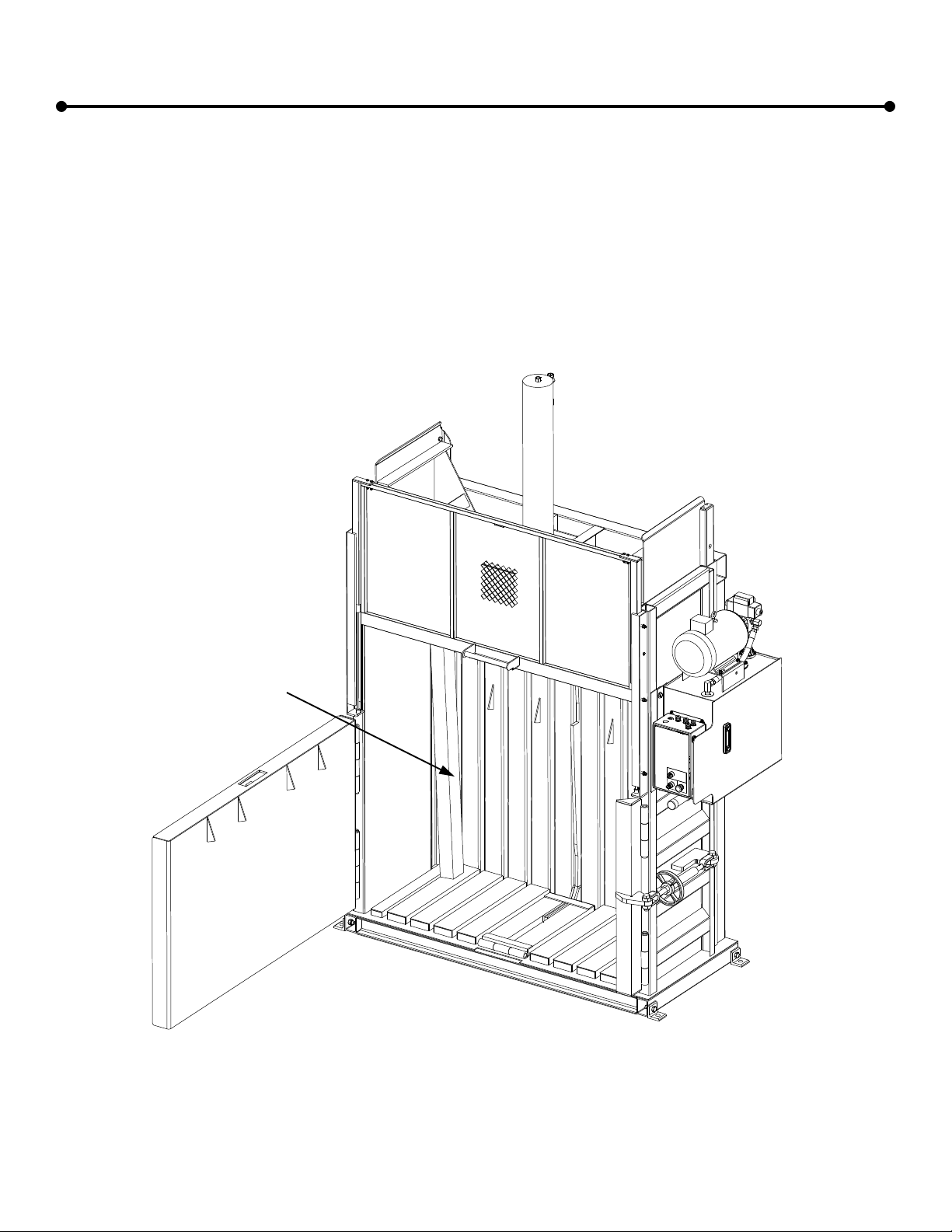
Making and Tying a Bale with Front Feed Wire Guide option.
1. Place a full sheet of cardboard to cover the top of the compacted material.
2. Close the loading door.
3. With the mode selector switch in “MANUAL DOWN”, insert the key into the start switch and turn to the “START” position
until the presshead begins to descend.
4. Remove the key. When the presshead descends and compresses the compacted material, the baler will stop and the
loading door will open.
5. CAUTION! Clear the area around the baler from all personnel and obstructions before proceeding!
6. Open the chamber door.
7. Insert the bale ties through the tie slots in the presshead first (see Figure 6) , feed wire through until it comes out of the
slot in the floor, pull each wire snug and tie.
Fig. 6
VB-60 Series Shown
Ejecting a Bale
1. Ensure that all personnel and obstructions have been cleared from the area around the baler.
2. Prepare an area in the front of the baler to eject the bale.
3. With the mode selector switch in “MANUAL UP” engage the bale eject system by pressing in on the bale eject handle.
Insert the key into the start switch and turn to the “START” position. The motor will start but the presshead will not move.
4. CAUTION! Do not stand in front of the baler while ejecting the bale!
5. Remove the key. Pull and hold the Stop / Pull to Raise button to raise the presshead and eject the bale.
6. Remove the ejected bale and clean any loose material from inside the chamber.
7. Close and latch the chamber door using the turnbuckle on the chamber door latch.
8. Close the loading door.
9. To reset the bale eject system, turn the mode selector switch to “AUTO”, insert the key into the start switch and turn to
the “START” position until the presshead begins to descend. The Bale Eject Handle will disengage automatically during
the downstroke.
10. Remove the key. At the end of the cycle, the baler will stop and the loading door will open.
WIRE GUIDE
TIE SLOT
BALE
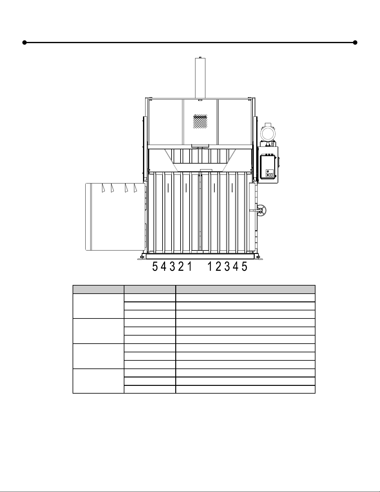
13
Baler Operation, cont.
Reference Parts page for bale ties.
Material Type Model Number Recommended Bale Tie Configuration
Corrugated
Cardboard
VB-42 Series Use tie slots 1, 2, & 3
VB-60 Series Use tie slots 1, 3, & 4
VB-72 Series Use tie slots 1, 3, 4, & 5
Shrink Wrap
Plastic
VB-42 Series Use tie slots 1, 2, & 3
VB-60 Series Use tie slots 1, 2, 3, & 4
VB-72-Series Use tie slots 1, 2, 3, 4, & 5
Plastic Bottles
VB-42 Series Use tie slots 1, 2, & 3
VB-60-Series Use tie slots 1, 2, 3, & 4
VB-72 Series Use tie slots 1, 2, 3, 4, & 5
Aluminum Cans
VB-42 Series Use tie slots 1, 2, & 3
VB-60 Series Use tie slots 1, 3, & 4
VB-72 Series Use tie slots 1, 3, 4, & 5
Fig. 4
VB-72 Series Shown

14
Lock Out / Tag Out Procedures
This procedure establishes the minimum requirements for the lockout of your baler for
service. It shall be used to ensure that the machine is isolated from all potentially hazardous
energy, and locked out before employees perform any servicing or maintenance activities where
the unexpected energization or start-up could cause serious injury or fatality due to electrocution
or due to entrapment in moving parts. This procedure should be performed only by an authorized,
qualified electrician.
1. Before locking baler out for service or repair, locate which breaker or disconnect applies to
the baler to be locked out. Notify all affected employees that a lockout system is going to be
utilized and the reason therefore.
2. If the machine or equipment is operating, shut it down by the normal stopping procedure.
3. Lock out the disconnect or breaker that controls the baler. If locking out a breaker use a
double-pole breaker lockout and lock.
4. Lockout the energy isolating devices with assigned individual locks. If more than one
person is servicing the baler, then a hasp with a lock for each service person shall be
used.
5. After ensuring that no personnel are exposed, and as a check on having closed the
appropriate breaker or disconnect, operate the start button to make certain the baler will
not operate. Then push the stop button. The baler is now locked out.
6. After the servicing and/or maintenance is complete and equipment is ready for normal
production operations, check the area around the machines or equipment to ensure that
no one is exposed.
7. After all tools have been removed from the baler and employees are in the clear,
remove the lockout device. Operate the start button to restore energy to the baler .
Before performing any maintenance, always "LOCK AND TAG OUT THE DISCONNECT."
Maintenance
15
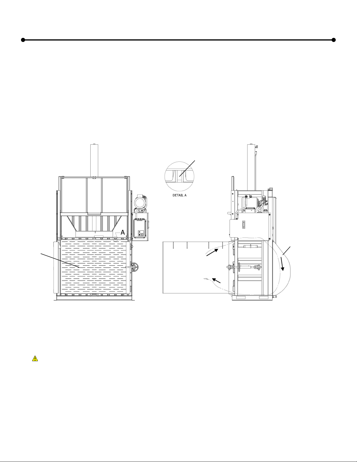
Chocking the Presshead
Before entering the bale chamber to perform any service tasks, the presshead should be chocked in conjunction
with following the Lock Out / Tag Out procedures as described on the previous page. The presshead should be sup-
ported with two 4”x4” wooden beams that are in excellent condition. DO NOT use the wood if its integrity is question-
able. The beams should be cut to length so they fit tightly in between the presshead and the baler floor when the
presshead is fully raised (see figure 5). The top of the beams should be placed in the rear-most corner on each side
of the baler. The bottom of the beams should be positioned into the outermost bale tie slot in the baler floor as illus-
trated below.
Maintenance, cont.
IMPORTANT! Chock presshead
on both sides with a 4”x4” wood-
en beam!
Fig. 5

16
Preventive Maintenance Schedule
Starting and adhering to a comprehensive preventive maintenance program will ensure and extend the trouble-
free operation of your baler. Particular attention should be given to the maintenance of the hydraulic system to ex-
tend the life of the baler.
Daily
Clean any loose material from the top of the presshead.
Clean any loose material from the tie slots in the floor of the bale chamber and underneath the dump tray after
dumping each bale. Follow Lock out / Tag out procedures and Presshead Chocking procedures as specified
elsewhere in this manual.
Clean the surface of the magnetic door latch and striker with a clean cloth.
Monthly
Lubricate the chamber door hinges.
Lubricate dump handle bushings.
Grease the turnbuckle for the chamber door latch.
Check the oil level with the presshead fully raised.
Check all hydraulic hoses for rubbing, chafing, deterioration, damage, and leaks.
Check all hydraulic fittings for loosening and leaks.
Check that all safety decals are present and legible.
Annually
We recommend having a
CRAM-A-LOT ®
Factory Authorized Service Technician perform the annual preventive mainte-
nance check. To coordinate a PM Check through
CRAM-A-LOT ®
Customer Support, call 1-800-754-4290.
Replace the hydraulic oil.
Check presshead guides for wear and adjust appropriately.
Check the cylinder mounting bolts for tightness.
Date Performed By Maintenance Interval Performed
1/1/03 Joe Fixit MonthlyAnnual
MonthlyAnnual
MonthlyAnnual
MonthlyAnnual
MonthlyAnnual
MonthlyAnnual
MonthlyAnnual
MonthlyAnnual
MonthlyAnnual
MonthlyAnnual
MonthlyAnnual
MonthlyAnnual
MonthlyAnnual
MonthlyAnnual
Preventive Maintenance History
Maintenance, cont.

17
Maintenance, cont.
Item Part Number Decal Description
1443005 “DANGER—Do Not Enter”
2443017 “WARNING—Magnetic Field. Pacemaker wearers stay back.”
3443012 “DANGER-Crushing Hazard”
4443013 “DANGER—Disconnect and Lock Out Power Before Opening this Panel”
5443007 “DANGER—XXX VOLTS. Turn off Power Before Disconnecting”
6440003 Red decal that indicates the voltage of the machine—placed on top of Item 5
7440075 “WARNING—Maximum Load Height”
8443001 “WARNING—Do Not Load, Operate, or Unload Unless 18 Years Old”
9440820 “DANGER—Pinch Point”
10 443009 “WARNING-Keep off Vertical”
11 443000 “WARNING-Do not Operate”
12 440455 “CAUTION-Operator 18yrs”
13 443014 “WARNING-Shock Arc Hazard”
Safety Decals
It is the responsibility of the owner / operator to ensure that all safety decals on the baler remain legible and com-
plete. Please refer to the section titled “Safety Orientation” for more information on the importance of these decals. If
a decal becomes illegible or lost, it may be ordered from CRAM-A-LOT ® Customer Support using the part numbers
provided below.
Call CRAM-A-LOT® Customer Support at 1-800-754-4290 to order decals.
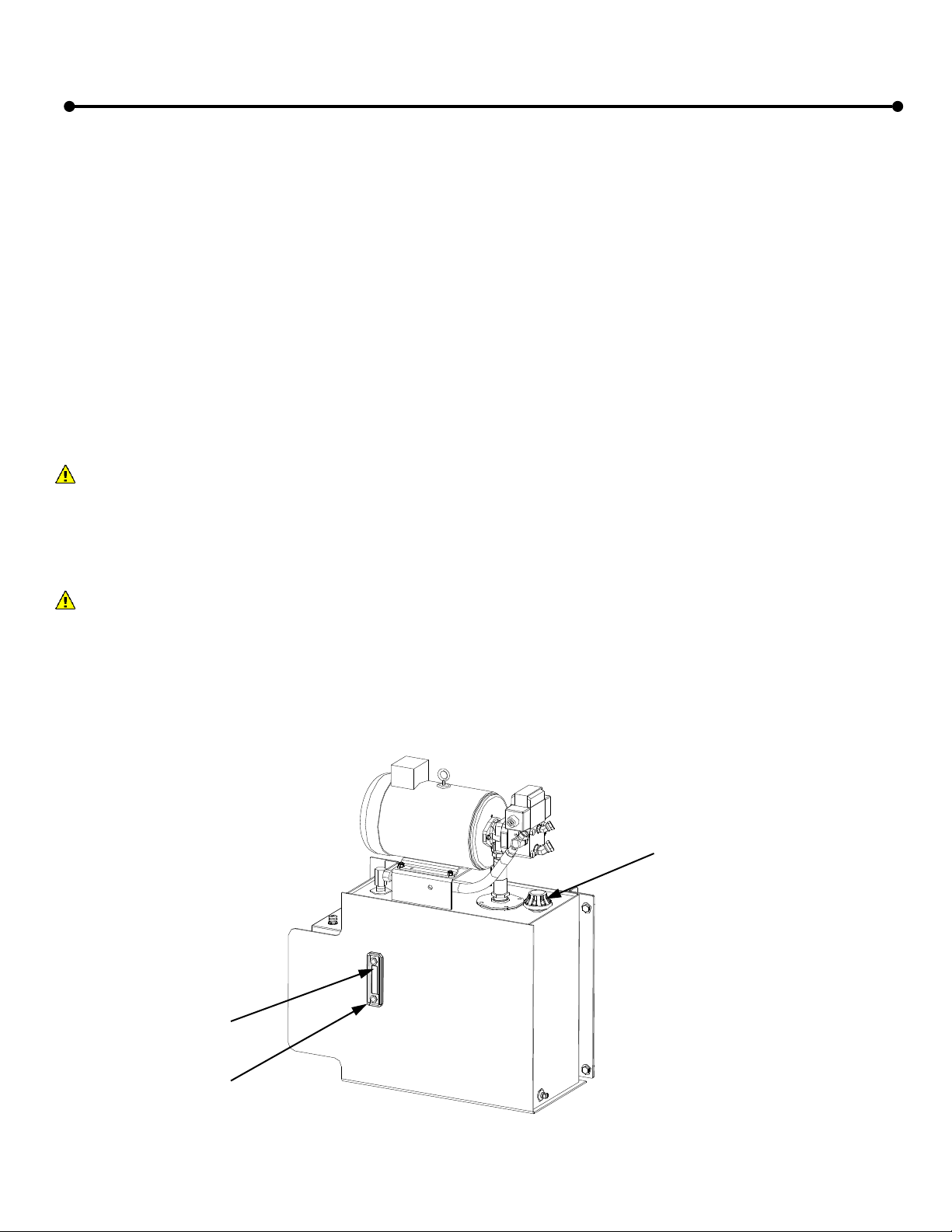
18
Oil Fill Line
Oil Sight Gauge
Vent / Oil Fill Port
Checking and Adding Oil
Time: 30 minutes
Tools: Eight foot step ladder, clean funnel
Parts: SAE 5W-20 high grade hydraulic oil (Sun 2105 or equivalent)
Supplies: Disposable shop towels
Tips: • Make sure that the presshead is fully raised when checking and filling the oil.
• Be patient when filling the oil.
• The cleanliness of the oil is very important to the long term reliability of the hydraulic system.
Checking the Oil Level
1. Run the machine to place the presshead in the fully raised position.
2. Check the oil by looking at the sight gauge on the side of the oil tank. If the oil level is below the black fill line on
the gauge, oil needs to be added to the tank.
Adding Oil
3. IMPORTANT! - Follow all Lock out / Tag out procedures before continuing this service procedure.
4. Place the step ladder in front of the power unit and use it to reach the top of the oil tank.
5. Using a disposable shop towel, clean any dust and debris from around the oil fill port to prevent contaminates
from entering the hydraulic system.
6. Remove the vent cap on the oil fill port.
7. Using a clean funnel, pour oil into the fill port until the oil level has reached the black fill line on the oil sight
gauge.
8. When the oil level reaches the black fill line, remove the funnel, replace the vent cap into the oil fill port.
9. Clean any spilled oil off of the machine with a disposable shop towel.
10. Remove the lock out / tag out according to procedures and restore power to the unit.
11. Check unit operation.
Maintenance, cont.
Fig. 7

19
If your cardboard baler is not operating properly, there are a few areas that can be checked before requesting
a service technician to come repair the machine. To save downtime and the cost of an unnecessary service call,
use the following guide to troubleshoot the machine before calling service. Do not attempt to service the machine
in areas beyond the scope of this troubleshooting guide. Call 1-800-754-4290 for repairs.
The motor won’t start when the key is turned.
1. Ensure that the emergency stop switch is not engaged.
2. Ensure that the loading door is fully closed if the baler is in “Auto” or “Manual Down” mode.
3. Ensure that the loading door is open if the baler is in “Manual Up” mode.
4. Ensure that the electromagnetic door latch and striker surfaces are clean.
5. Ensure that the disconnect or circuit breaker is turned on.
6. If the motor still won’t start, call CRAM-A-LOT® Customer Support for repairs.
The motor runs but the presshead won’t move.
If you are operating the baler in the “Manual Up” mode:
1. In “Manual Up” mode, it is necessary to pull out on the emergency stop switch to raise the presshead.
2. If the presshead still won’t raise, call CRAM-A-LOT® Customer Support for repairs.
If you are operating the baler in the “Auto” or “Manual Down” modes:
3. Ensure that the loading door is fully closed.
4. Ensure that the electromagnetic door latch and striker surfaces are clean.
5. Ensure that the chamber door is fully closed.
6. If the presshead still won’t move, call CRAM-A-LOT® Customer Support for repairs.
The loading door won’t open so material can be loaded.
1. Turn the key to the “Off” position and the loading door should raise automatically.
2. If the door still won’t raise, call CRAM-A-LOT® Customer Support for repairs.
The loading door won’t stay closed.
1. Ensure that the key is turned to the “On” position.
2. Ensure that the emergency stop switch is not engaged.
3. Ensure that the mode selector switch is in the “Auto” or “Man Down” positions.
4. Ensure that the electromagnetic door latch and striker surfaces are clean.
5. Ensure that the chamber door is fully closed.
6. If the door still won’t stay closed, call CRAM-A-LOT® Customer Support for repairs.
The bale ties won’t go through the slots in the floor or presshead to tie a bale.
1. Ensure that the chamber door is open.
2. Ensure that the correct end of the bale tie is being guided through the slots.
3. Ensure that a full sheet of cardboard has been laid on the chamber floor before the bale was made.
4. Ensure that a full sheet of cardboard has been laid on top of the full bale before the presshead was lowered.
5. If the problem persists, call CRAM-A-LOT® Customer Support for additional guidance.
The bale won’t eject.
1. Ensure that the dump handle was engaged before the machine was operated in the “Manual Up” mode to
dump the bale.
2. On newer balers, the paint on the inside of the bale chamber may prevent the bale from ejecting well. The
bales will eject more easily as each consecutive bale is ejected.
3. While ejecting the bale the motor may shut off. If this occurs, the baler cycle timer has timed out. Simply
turn the key switch to restart the baler and proceed with ejecting the bale.
4. If the bale will still not eject properly, call CRAM-A-LOT® Customer Support for repairs.
Troubleshooting

20
Troubleshooting cont.
POSSIBLE PROBLEM ERROR DISPLAYED CODE RECOMMENDATION
The Baler will not start.
STOP BUTTON
IS IN THE “STOP”
POSITION
1 Pull the STOP button out to the “RUN”
position.
ELECTROMAGNETIC
LOCK FAILED
“OPEN”
2
Close and latch the Loading Door.
Check the Door Position Sensor for proper
alignment to the magnet on the Door Strike
Plate.
Check the Electromagnetic Lock.
Replace the Electromagnetic Lock.
ELECTROMAGNETIC
LOCK FAILED
“CLOSED”
3
Cycle power to unlock the Loading Door.
Close and latch the Loading Door.
Check the Door Position Sensor for proper
alignment to the magnet on the Door Strike
Plate.
Check the Electromagnetic Lock.
Replace the Electromagnetic Lock.
When you release the key the
Baler stops.
UPPER MAGNETIC
INTERLOCK SWITCH
FAILED “OPEN”
4
Close and latch the Loading Door.
Check the Upper Magnetic Interlock Switch
for proper alignment to the magnet on the Load-
ing Door.
Check the Upper Magnetic Interlock
Switch.
Replace the Upper Magnetic Interlock
Switch.
When the ram retracts to the
top, the Baler continues to
run.
UPPER MAGNETIC
INTERLOCK SWITCH
FAILED “CLOSED”
5
Check the Upper Magnetic Interlock Switch
mounting bracket for proper operation.
Check the Upper Magnetic Interlock
Switch.
Replace the Upper Magnetic Interlock
Switch.
The Baler will not start. MOTOR STARTER
FAILED 6
Check the Motor Starter Overload and press
“RESET” if necessary.
Check power to the Motor Starter coil.
Replace Motor Starter.
PICOVB07 TROUBLESHOOTING GUIDE
This manual suits for next models
15
Table of contents


