manuals.online logo
Brands
  1. Home
  2. •
  3. Brands
  4. •
  5. FRAME IT ALL
  6. •
  7. Lawn And Garden Equipment
  8. •
  9. FRAME IT ALL Stack & Extend User manual

FRAME IT ALL Stack & Extend User manual

300001003
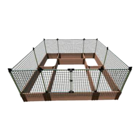
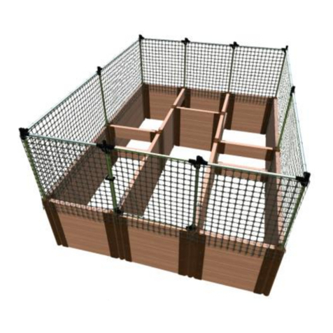
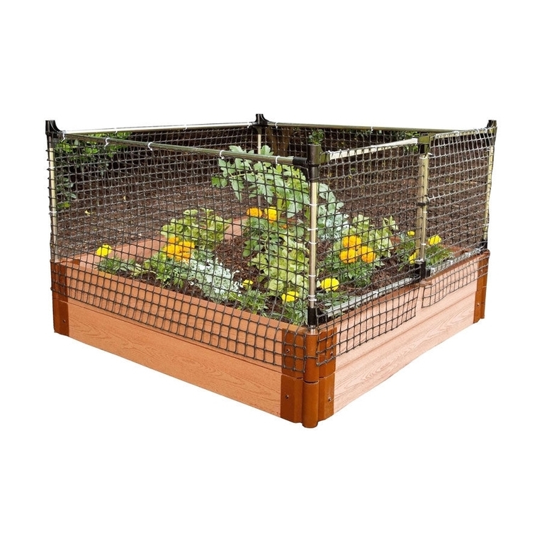
ANIMAL BARRIER
*Stack & **Extend
- Used with *curved raised bed
Customer Service: 1800-914-9835 | support@frameitall.com
© Frame It All. All Rights Reserved.
**Extendable: Combine 2 or more kits to add additional
gates and expand barrier's length--hinged connectors allow
use on beds made of 4' boards.
*Stackable –combine or more
kits to create as high a barrier as
needed
RAISED BED SOLD SEPARATELY
Each kit will protect a 4ft. x 4ft. garden to a height of 2 feet.
Additional kits provide more protection by increasing the
length or height of the basic 4ft x 4ft x 2ft high module..
KIT CONTAINS:
x 2 x 4 x 1 x 1 x 2 x 1 x 1 x 1
x 4 x 1 x 1
x 2 x 50
x 4 x 3
x 4
8
x 1
x 4
17
11 14 15
16
1.37”
43
1.37”
15
1.37” 6
1.06”
7
1.06”
1.06”
12 13
x 4
x 2
x 1
x 2
20
19
22
21
18
910
2
Zip tie
Use this part only if
joining 2 or more kits
to extend animal
barrier
Customer Service: 1800-914-9835 | [email protected]
ASSEMBLY INSTRUCTIONS
Your animal barrier kit goes together by sliding the ends of the metal tubes
into the plastic connectors to create a frame, then zip-tying netting to the
frame.
STEP 1: BUILD THE LEFT GATE
FOURTH: Complete the left
gate frame by connecting an
"L" connector (9) to each
end of another square tube
(17) and connecting this
tube to the rest of the frame
to create a rectangle.
THIRD: Add two square tubes (18) to create the top and the bottom
edges of the left gate--Insert one square tube into the square connector
of the top hinge and another into the square connector of the bottom
hinge.
SECOND: Use connectors 7& 21 to
create the lower hinge for the left gate,
as shown in the box to the right. Slide
the lower hinge about 6" past the
bottom end of metal tube (20).
FIRST: Use
connectors 2, 5, 3, &
13 to form the upper
left gate hinge (as
shown in the box to
the right). Next, insert
round metal tube (20)
into the bottom of of
the hinge assembly.
(see main diagram)
FIFTH: Using zip ties (14), attach one of smaller
pieces of netting (16) to all of the tubes of the
gate frame. (See diagram in Step 5 of the
instructions).
STEP 3: Attach the gates to the raised bed boards
Customer Service: 1800-914-9835 | [email protected]
ASSEMBLY INSTRUCTIONS –continued
STEP 2: BUILD THE RIGHT GATE
FIRST: Slide the round tubes at the
bottom of each gate section into the
bracket connecting the raised bed
boards. (You may need to remove
the cap on top of these brackets--
the cap will be replaced with the cap
on the gate assembly (Part 21)
Second: Install gate stopper (12) with screws
(11) on the inner side of the board to prevent
the gate from swinging inward
View from the inner side of
the board.
FIRST: Use connectors
2, 4, 5, & 13 to form the
upper right gate hinge
(as shown in the box to
the right). Next, insert
round metal tube (20)
into the bottom of of
the hinge assembly.
(see diagram in the
small box.)
SECOND: Use connectors
6, 8& 21 to create the
lower hinge for the right
gate, as shown in the box
to the right. Slide the
lower hinge about 6" past
the bottom end of metal
tube (20). FIFTH: Finish the right gate frame by
connecting this tube to the rest of the
frame to create a rectangle.
THIRD: Add two square tubes (18) to
create the top and the bottom of the right
gate frame. Insert one square tube into the
square connector of the top hinge and
another into the square connector of the
bottom hinge.
FOURTH: Add an "L" connector (9)
to each end of square tube (17,
which has the gate-latch) with the L
connectors opening in the opposite
direction from the gate latch.
Customer Service: 1800-914-9835 | [email protected]
ASSEMBLY INSTRUCTIONS –continued
STEP 4: Attach rest of framework to gate frame
STEP 5: APPLY NETTING
Apply the netting to both the vertical and horizontal tubes of the gates and
main frame using zip ties. Attach the top of the netting flush with the upper
tubes so the netting hangs over your raised bed.
SECOND: Slide three round
tubes (19) into the
connectors to create the
remaining upper edges of
the animal barrier.
FIRST: Use connectors
(2, 1& 13) to form the
joints for each of the
back corners at the top
of the animal barrier.
Then, place a round tube
(20) into the bracket of
the raised bed and slip a
joint assembly onto this
vertical tube. (See
diagram in box)
Customer Service: 1800-914-9835 | [email protected]
JOINING MULIPLE ANIMAL BARRIER KITS
Stacking kits to make a higher barrier –Assemble the kit for the upper level in the same way as for
the lower level except, before installing the gate assemblies, slide a round sleeve, (Part 22) onto the
corner post of the gate, below the gate hinges.
NOTE: Each Animal Barrier kit contains one Part 22, which is not needed unless stacking kits.
Slide the round sleeve
(22) below the short
sleeve.
Slide the round
sleeve (22)
below the hinge
connector
EXPANDING BARRIER AREA WITH MULITPLE KITS - EXTENSION OPTION 1: PLACING GATES PLACED IN
DIFFERENT AREAS OF THE GARDEN BED
Customer Service: 1800-914-9835 | [email protected]
To extend your animal barrier
with additional kits, simply
connect them in a loop using
additional vertical poles (Part 20)
and Horizontal Poles (Part 19)
connected with Part 1 & 2 as
shown.
Customer Service: 1800-914-9835 | [email protected]
JOINING MULIPLE ANIMAL BARRIER KITS -(continued)
EXTENSION OPTION 2: PLACING THE GATES NEXT TO EACH OTHER
NOTE: When installing an extension kit on the left side of the Kit 1,
instead of on the right side as shown in the diagram, Large Sleeve (5)
from the right gate of Kit 1 will be replaced with Gate Hinge (4) from
the right gate of Kit 2.
Remove Small Sleeve (8)
from the right gate of Kit
1 and replace it with
Gate Hinge (7) from the
Kit 2. The round tube
now supports the
bottom gate hinges from
both kits.
Remove Large Sleeve (5) from the right gate
of Kit 1 and replace it with Gate Hinge (3) from
the left gate of Kit 2.

This manual suits for next models

1

Other FRAME IT ALL Lawn And Garden Equipment manuals
FRAME IT ALL 300001068 User manual

FRAME IT ALL

FRAME IT ALL 300001068 User manual

FRAME IT ALL 300001066 User manual

FRAME IT ALL

FRAME IT ALL 300001066 User manual

FRAME IT ALL 800002179 User manual

FRAME IT ALL

FRAME IT ALL 800002179 User manual

FRAME IT ALL 70001024-MD550 User manual

FRAME IT ALL

FRAME IT ALL 70001024-MD550 User manual

FRAME IT ALL Stack & Extend VEGGIE WALL User manual

FRAME IT ALL

FRAME IT ALL Stack & Extend VEGGIE WALL User manual

FRAME IT ALL 200001090 User manual

FRAME IT ALL

FRAME IT ALL 200001090 User manual

FRAME IT ALL Stack & Extend User manual

FRAME IT ALL

FRAME IT ALL Stack & Extend User manual

FRAME IT ALL 300001058 User manual

FRAME IT ALL

FRAME IT ALL 300001058 User manual
FRAME IT ALL Fort Bragg 8' x 8' User manual

FRAME IT ALL

FRAME IT ALL Fort Bragg 8' x 8' User manual

FRAME IT ALL Topolski User manual

FRAME IT ALL

FRAME IT ALL Topolski User manual

FRAME IT ALL Inner Roboto 800002114 User manual

FRAME IT ALL

FRAME IT ALL Inner Roboto 800002114 User manual

FRAME IT ALL 170001018-MD350 User manual

FRAME IT ALL

FRAME IT ALL 170001018-MD350 User manual

FRAME IT ALL Stack & Extend VEGGIE WALL User manual

FRAME IT ALL

FRAME IT ALL Stack & Extend VEGGIE WALL User manual

FRAME IT ALL Stack & Extend User manual

FRAME IT ALL

FRAME IT ALL Stack & Extend User manual

FRAME IT ALL 300001178 User manual

FRAME IT ALL

FRAME IT ALL 300001178 User manual

FRAME IT ALL 300001078 User manual

FRAME IT ALL

FRAME IT ALL 300001078 User manual

FRAME IT ALL 300001063 User manual

FRAME IT ALL

FRAME IT ALL 300001063 User manual

FRAME IT ALL 300001228 User manual

FRAME IT ALL

FRAME IT ALL 300001228 User manual

FRAME IT ALL 800002123 User manual

FRAME IT ALL

FRAME IT ALL 800002123 User manual

FRAME IT ALL Cumberland User manual

FRAME IT ALL

FRAME IT ALL Cumberland User manual

FRAME IT ALL 800001191 User manual

FRAME IT ALL

FRAME IT ALL 800001191 User manual

FRAME IT ALL 300000078 User manual

FRAME IT ALL

FRAME IT ALL 300000078 User manual

FRAME IT ALL 70001019-MD350 User manual
FRAME IT ALL

FRAME IT ALL 70001019-MD350 User manual

FRAME IT ALL 70001025-MD250 User manual
FRAME IT ALL

FRAME IT ALL 70001025-MD250 User manual

Popular Lawn And Garden Equipment manuals by other brands

FM Mattsson 4293 Installation instruction

FM Mattsson

FM Mattsson 4293 Installation instruction

3M Health Care Steri-Vac 8XL Operator's manual

3M

3M Health Care Steri-Vac 8XL Operator's manual

Gronomics RGB 34-34 Assembly instruction

Gronomics

Gronomics RGB 34-34 Assembly instruction

Mosquito Magnet Commander Xperts quick start guide

Mosquito Magnet

Mosquito Magnet Commander Xperts quick start guide

EGO EG0800 Operator's manual

EGO

EGO EG0800 Operator's manual

Wasserstein Dartwood Solar Mole Repellent user manual

Wasserstein

Wasserstein Dartwood Solar Mole Repellent user manual

Cocraft LR36 Original instructions

Cocraft

Cocraft LR36 Original instructions

Montgomery Ward ZYJ-290C Owner's guide and parts list

Montgomery Ward

Montgomery Ward ZYJ-290C Owner's guide and parts list

DANA 4360-120 parts list

DANA

DANA 4360-120 parts list

Nakayama BS2000 user manual

Nakayama

Nakayama BS2000 user manual

OWIM Z31913 Operation and safety notes

OWIM

OWIM Z31913 Operation and safety notes

NoFli Standard 26 User manual & installation guide

NoFli

NoFli Standard 26 User manual & installation guide

Expand-it ALT-03 Operator's manual

Expand-it

Expand-it ALT-03 Operator's manual

juwel Aeroplus 6000 manual

juwel

juwel Aeroplus 6000 manual

Makita UM164D Series instruction manual

Makita

Makita UM164D Series instruction manual

Atlantic 74243 product manual

Atlantic

Atlantic 74243 product manual

Maxim MSAT36 quick start guide

Maxim

Maxim MSAT36 quick start guide

Craftsman 19A70041791 installation manual

Craftsman

Craftsman 19A70041791 installation manual

manuals.online logo
manuals.online logoBrands
  • About & Mission
  • Contact us
  • Privacy Policy
  • Terms and Conditions

Copyright 2025 Manuals.Online. All Rights Reserved.