ASTEC NT5C06D User manual

Astec Advanced Power Systems
A
part of Emerson Network Power
UM5C06D ( 169-2071-504 )
Helios Rectifier 25/48 Single Phase -48V, 25 A
Power Factor Corrected Switch Mode Rectifier
NT5C06D
Installation and User Manual
P0831010 Standard 7.00 May 2001


Astec Advanced Power Systems
Helios Rectifier 25/48NT5C06D Installation and User Manual
Helios Rectifier 25/48 Single Phase -48V, 25A
Power Factor Corrected Switch Mode Rectifier
NT5C06D
Installation and User Manual
Manual Number : UM5C06D ( 169-2071-504 )
Manual Status : Standard
Manual Issue : 7.00
Release Date : May 2001
P0831010
Copyright 2001 Astec Advanced Power Systems Ltd
All Rights Reserved
Published in Canada
The information contained in this manual is the property of Astec Advanced Power Systems and is subject to change without
notice. Astec Advanced Power Systems Ltd reserves the right to make changes in design or components as progress in
engineering and manufacturing may warrant. Except as specifically authorized in writing by the V.P. of Engineering and Product
Manufacturing of Astec Advanced Power Systems Ltd, the holder of this manual shall keep all information contained herein
confidential and shall protect same, in whole or in part, from disclosure and dissemination to all third parties, and use the same
for start-up, operation, troubleshooting, and maintenance purposes only. Any modification to the equipment must be approved
by the person responsible for product safety, and design quality at Astec Advanced Power Systems Ltd to ensure that the
equipment complies with the operation standards.
This equipment generates, uses, and can radiate radio frequency energy, and if not installed and used in accordance with the
instructions contained in the Installation and User Manuals, can cause harmful interference to radio communications. Operation
of this equipment in a residential area is likely to cause harmful interference, in which case the user will be required to correct
the interference at his own expense.
Astec Advanced Power Systems
A part of Emerson Network Power
Helios Candeo is a trademark of Astec International Ltd. The Emerson logo is a trademark and service mark of Emerson Electric Co.


5
Helios Rectifier 25/48NT5C06D Installation and User Manual
Publication history
May 2001
Standard issue 7.00. Manual modified to reflect the Emerson identity.
( EC 102-26438 )
September 1999
Standard 6.0. Document modified to be in accordance with Astec
standards. (ECN 102-17331)
May 1999
Standard 5.0. Document modified to reflect Astec identity. Figure 11
modified. (ECN 102-14852)
March 1997
Std. release 4.0. New Float Voltage and Current Limit Factory
Setting.
August 1996
Std. release 3.0. Removal of extended temperature rectifier models
Table 1 and Table 6 (note) revised.
February 1996
Std. release 2.0. This issue is to cover the revision of “Installation and
Start-Up” procedures and Figures 1, 2, 3, 7 and 9
November 1995
Standard release 1.0.

6 Publication history
UM5C06D ( 169-2071-504 ) P0831010 Standard 7.00 May 2001
This page is left blank intentionally.

7
Helios Rectifier 25/48NT5C06D Installation and User Manual
Contents
Introduction.............................................................................................................. 11
Description.................................................................................................... 11
Applications .................................................................................................. 12
Equipment Identification .................................................................................. 12
MPS75 NT5C10C(X) power shelf (23-inch) .....................................................12
Helios Rectifier 25/48 NT5C06D(X) –48 V / 25 A Switch Mode Rectifier........13
Specifications .......................................................................................................... 15
Electrical specifications................................................................................... 15
Output noise and ripple .........................................................................................16
Efficiency and Power Factor .................................................................................16
Reliability..............................................................................................................16
Heat Dissipation ...................................................................................................16
Electromagnetic interference (EMI) .......................................................................16
Environmental specifications ............................................................................ 17
Operating..............................................................................................................17
Transportation......................................................................................................17
Storage.................................................................................................................17
Installation and start up.......................................................................................... 19
Tools and test equipment................................................................................. 19
Installing the power shelf................................................................................. 19
Wiring the power shelf..........................................................................................20
Installing the AC power.........................................................................................21
DC Conductors Installation ...................................................................................22
Control and Alarm Connections .............................................................................23
Verification ...........................................................................................................28
Installing the rectifier...................................................................................... 28
Factory setting .....................................................................................................28
Rectifier meter accuracy.......................................................................................29
Start-up and verification .......................................................................................29
Slope Load Share ..................................................................................................32

8 Contents
UM5C06D ( 169-2071-504 ) P0831010 Standard 7.00 May 2001
Forced Load Share ................................................................................................32
Load Share Adjustment Procedure ........................................................................32
Operation.................................................................................................................. 33
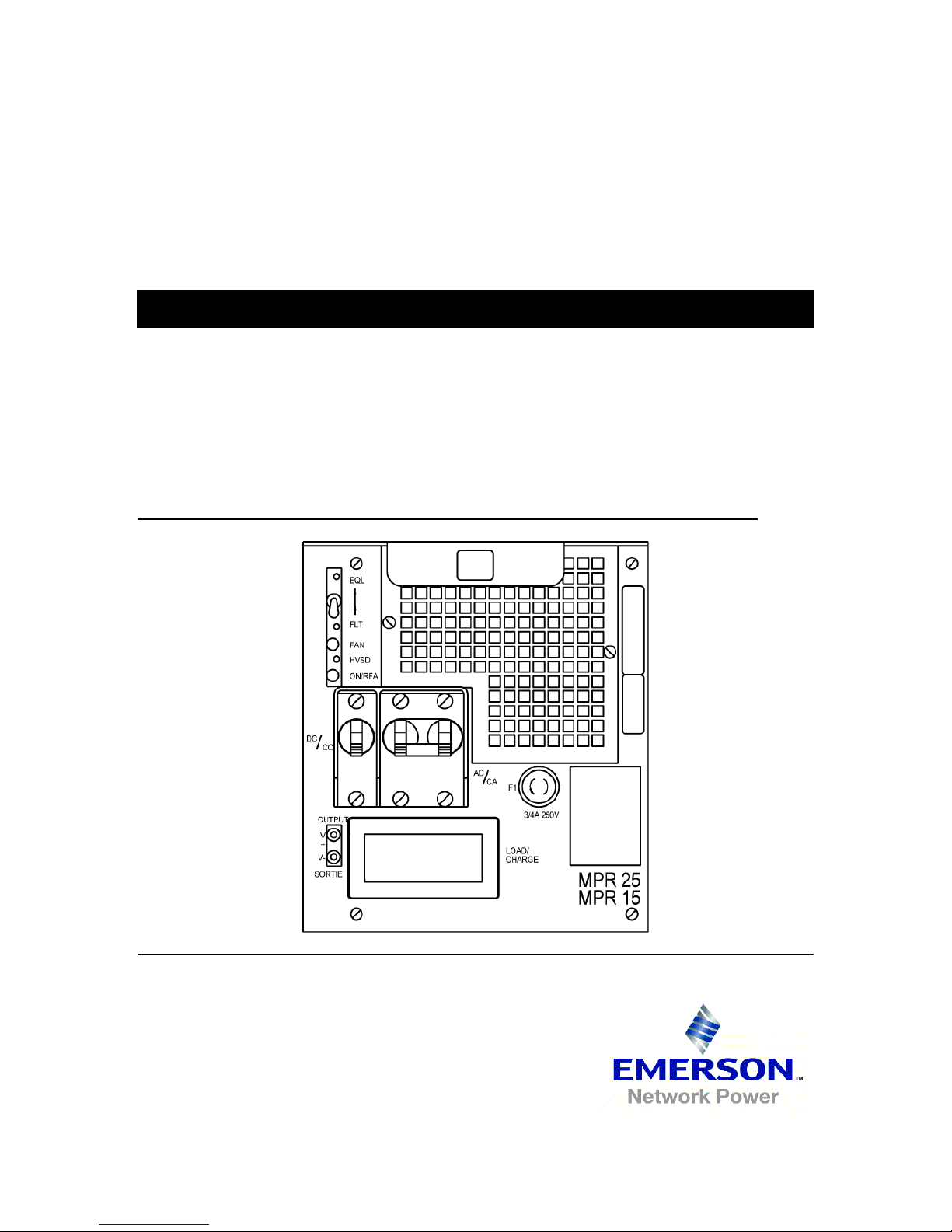
Front panel controls........................................................................................ 34
Features ....................................................................................................... 34
Local float / equalize control .................................................................................34
High voltage shutdown (HVSD) - local ...................................................................34
High voltage shutdown - remote............................................................................34
Start-up delay.......................................................................................................35
Test points (V+, V-) ..............................................................................................35
Indicators .............................................................................................................35
Rectifier failure alarm (RFA)..................................................................................35
Fan failure alarm...................................................................................................35
Internal high voltage shutdown (HVSD) .................................................................35
Local ON/OFF control (AC breaker)........................................................................36
Remote ON/OFF control ........................................................................................36
Remote voltage sensing ........................................................................................36
Sense fail alarm (SEN FAIL)...................................................................................36
Current limiting .....................................................................................................36
Soft start / walk-in ...............................................................................................36
AC inrush current..................................................................................................36
Sequential start ....................................................................................................37
Parallel operation..................................................................................................37
Discharge of output capacitors .............................................................................37
Input AC voltage monitor ......................................................................................38
Thermal shutdown ................................................................................................38
Remote high voltage shutdown .............................................................................38
Local / remote high voltage shutdown reset ..........................................................38
Remote equalize control........................................................................................38
Power interface edge connector............................................................................38
Signal interface connector ............................................................................... 39
Maintenance............................................................................................................. 41
Float / equalize............................................................................................... 41
High voltage shutdown (HVSD) ......................................................................... 42
Cooling fan.................................................................................................... 42
Fan replacement ...................................................................................................43
Power shelf................................................................................................... 45
Troubleshooting ....................................................................................................... 47
Alarm indication............................................................................................. 47

Contents 9
Helios Rectifier 25/48 Installation and User Manual
RFA fault..............................................................................................................47
SEN FAIL fault......................................................................................................48
Erratic load fault...................................................................................................48
Current or voltage float fault ................................................................................48
Appendix A: Replacement parts.............................................................................. 49
Appendix B: Technical service assistance............................................................. 51
Local toll-free prefixes .................................................................................................51
Toll-free technical assistance numbers.........................................................................52
List of terms and acronyms..................................................................................... 53
List of Figures
Figure 1 - MPS75 Modular Power Shelf-NT5C10C with 8-pin signal cables .................13
Figure 2 - MPS75 Modular Power shelf- NT5C10C with 26-pin signal connectors........14
Figure 3 - NT5C06D Switch Mode Rectifier.................................................................14
Figure 4 - Power shelf common AC connection.............................................................21
Figure 5 - Power shelf individual AC connection...........................................................22
Figure 6 - Connecting the DC power shelf ....................................................................23
Figure 7 - No controller, remote sensing connection for 8-pin signal cable shelves........26
Figure 8 - No controller, remote sensing connection for a 26-pin signal connector
shelf...........................................................................................................27
Figure 9 - NT5C06D - front view..................................................................................34
Figure 10 - Power interface connections......................................................................39
Figure 11 - Control signal connections .........................................................................40
Figure 12 - NT5C06D rear view...................................................................................44
List of Tables
Table 1 - Electrical specifications.................................................................................15
Table 2 - AC cable wire size.........................................................................................21
Table 3 - AC Fuses.......................................................................................................21
Table 4 - DC cable wire size.........................................................................................23
Table 5 - Rectifier and Controller interface connections (8-pin connectors) ..................24
Table 6 - Rectifier and Controller interface connections (26-pin connector)..................24
Table 7 - Rectifier settings ..........................................................................................28
Table 8 - Indicators......................................................................................................35
Table 9 - System fault diagnosis..................................................................................47
List of Procedures
Procedure 1 - Installing the power shelf.......................................................................20
Procedure 2 - Verification ............................................................................................28
Procedure 3 - Rectifier installation procedure...............................................................28
Procedure 4 - Starting up the rectifier..........................................................................29
Procedure 5 - Adjusting the load share.........................................................................32
Procedure 6 - Adjusting the float / equalize ..................................................................41
Procedure 7 - Replacing the fan ...................................................................................43

10 Contents
UM5C06D ( 169-2071-504 ) P0831010 Standard 7.00 May 2001
This page is left blank intentionally.

11
Helios Rectifier 25/48NT5C06D Installation and User Manual
1. Introduction
Description
The NT5C06D Switch Mode Rectifier is rated for 25 A at -48 V DC. This
rectifier incorporates AC input power factor correction circuitry, is highly
efficient and lightweight (15 lbs.). It is fully connectorized and plugs into a
power shelf into which up to three rectifiers can be installed. The rectifier is
forced air cooled with air entering from the front and exhausting out the rear
of the power shelf.
Separate or common AC power feeds are connected to the power shelf to
provide power to each rectifier through the back plane connectors. The
rectifier requires a single phase AC source at a nominal voltage of 208/240 V
AC, 50 or 60 Hz. The AC power can be supplied from a single phase source
or a three-phase system connected phase to phase. The rectifier can also be
powered from a 380 V AC WYE system connected phase to neutral (that is,
220 V phase-neutral).
The negative and positive outputs of each rectifier are connected to two
common busses (BAT -48 and BAT RTN +). The power shelf is designed
for a typical capacity of 75 A. The design of the rectifiers allows rectifiers
located in the same power shelf, or other shelves, which are connected in
parallel, to share the load, either by forced load share or by an output
negative slope method.
The back plane of the power shelf is equipped with two types of signal
connectors. One is an eight-pin (male) connector that provides the interface
to analog type controllers. The other connector is a twenty-six-pin flat cable
(female) type connector compatible with the Helios system family and
provides a larger diagnostic capability.
Each rectifier provides a variety of monitoring and alarm features such as,
rectifier failure alarm, fan fail alarm, ac fail alarm, remote sensing, sense fail
alarm, local and remote high voltage shutdown, automatic high voltage
shutdown reset, temporary release, remote and local equalize, and remote
shunt monitoring.

12 Introduction
UM5C06D ( 169-2071-504 ) P0831010 Standard 7.00 May 2001
Applications
The rectifier is designed to function as the prime source of power for
equipment requiring -48 V DC. It will also operate as a battery charger or as
a battery replacement (batteryless operation). Its low output noise and good
voltage regulation, combined with a 0.01% V coefficient for each degree C of
temperature, provides an excellent charging facility to maintain a battery fully
charged.
The NT5C06D rectifier is designed to operate continuously in a small or
large power system. The NT5C06D is compatible with all other Astec
rectifiers, and can be interfaced with other commercially available standard
(compatible) rectifiers and power plants. The NT5C06DA/DB is designed to
operate in temperatures ranging from 0°C to 65°C.
Equipment Identification
This section contains a description of the major components and available
options for the NT5C06D Rectifier, and the MPS75 power shelves.
NT5C06DA -48 V / 25 A Switch Mode Rectifier, brown
NT5C06DB -48 V / 25 A Switch Mode Rectifier, dolphin grey
NT5C10C(X) Rack mount power shelf family, 23” mounting
Note:Many shelf models, with different colors and features, are
available.
MPS75 NT5C10C(X)
power shelf (23-inch)
The MPS75 is a power shelf that can support up to three NT5C06 rectifiers.
The rectifiers plug into the shelf, which provides interconnection points for
AC input, DC output, and alarm and control signals. Each power shelf
requires either three AC feeds (one for each rectifier) for the individual AC
models, or a single AC feed for the three shelf rectifiers for the common AC
models. Its output connects to the charge busbar or to the load distribution
panel through two cablesbattery and battery return. Each rectifier position
has its own connector-terminated alarm and control cable going to the power
plant control and monitor unit.

Introduction 13
Helios Rectifier 25/48 Installation and User Manual
Helios Rectifier 25/48
NT5C06D(X) –48 V / 25 A Switch Mode Rectifier
The NT5C06D provides -48 V / 25 A of isolated, filtered, and regulated DC
power from a single phase AC source, for powering a load while charging a
positive grounded battery. The output voltage can be adjusted from 46.0 to
56.0 V for floating a 23 or 24 cell battery string.
The rectifier is designed for automatic precharge upon insertion into the
MPS75 power shelf. When the NT5C06D is plugged into a power shelf with
battery back-up, or with other rectifiers running, the DC circuit breaker must
be in the OPEN position (OFF position).
Each rectifier plugs into the MPS75 power shelf and does not require any
other connections. The rectifier is equipped with a 13 A, two-pole, AC input
circuit breaker; a 35 A, single-pole, DC output circuit breaker; a digital
ammeter; and a set of LEDs, switches and potentiometers for threshold
adjustments and alarm indication. The rectifier uses high frequency switching
technology, is cooled by forced air, and can be equipped with an optional air
filter.
Figure 1 - -MPS75 Modular Power Shelf-NT5C10C with 8-pin signal cables
Height: 178 mm (7.0 inches)
Depth: 305 mm (12.0 inches)
Width: 533 mm (21.0 inches)
Weight: 10.5 kg (23.0 lbs)
AC
Connections
DC Connections
Signal Cables
to Controller

14 Introduction
UM5C06D ( 169-2071-504 ) P0831010 Standard 7.00 May 2001
Figure 2 - MPS75 Modular Power shelf- NT5C10C with 26-pin signal connectors
Mounting
holes (4)
Signal cable connection DC connection
Mounting
holes (4)
Figure 3 - NT5C06D Switch Mode Rectifier
Height: 168 mm (6.60 inches)
Depth: 260 mm (10.25 inches)
Width: 149 mm (5.85 inches)
Weight:6.8 kg (15 lbs)
EQL
FLT
FAN
HVSD
ON RF A
DC
CC
OUTPUT
V+
V-
SO RTIE
LOA D
CHARG E
3MA 250V
F1
AC
CA
MPR25
MPR15

15
Helios Rectifier 25/48NT5C06D Installation and User Manual
2. Specifications
Electrical specifications
The NT5C06D rectifier operates within the electrical specifications listed in
Table 1. (Refer to the Product Specification which can be obtained from the
Engineering department of Astec Advanced Power Systems).
Table 1 - Electrical specifications
Input Voltage Rating: Nominal 208 / 240 V AC single-phase, 47-63 Hz.
Input Voltage Range 176 to 264 V AC.
Starting range 184 to 260 V AC.
When three-phase 208 / 240 V AC source is available to power the
MPS75, it is preferable to distribute the rectifiers among the phases.
Input Current Rating: 7.5 A nominal at 208 V AC input and -56 V DC, 25 A output. Use RW-
90 wire (or equivalent) as listed in Table 2.
Recommended AC Service
Input Fusing:
Two slow flow fusePRN type or equivalent, one for each AC line
input; or one slow trip circuit breaker for each rectifier, as listed in
Table 3.
Output Voltage Rating: Float: -46 V DC to -56 V DC
Equalize: 0 - 4 V DC over float. Maximum -59.5 V DC.
Output Current Rating: 25 A for each rectifier.
Input Protection: Two-pole 13 A circuit breaker, opens both lines for 208 / 240 V AC
service.
continued

16 Specifications
UM5C06D ( 169-2071-504 ) P0831010 Standard 7.00 May 2001
Table 1 - Electrical specifications ( continued )
Output Protection: A single pole 35 A circuit breaker is connected in series with the
negative output lead of the rectifier.
The rectifier contains an adjustable output current limit circuit for
protection against damage from overloads. This circuit is factory set to
limit the output current to 30 A. It can, however, be adjusted from
12.5 A to 30 A.
Output Regulation: At point of regulation: within ± 0.5% of the selected value for all
specified input and output variations and within ± 1% for any
combination of specified input, output, and environmental conditions.
Output noise and ripple
Less than 22 dBrnC at voice frequency (with or without batteries and
measured at the point of regulation) from a 1 A load current to full load,
including the current limit mode. Less than 32 dBrnC for loads less than 1 A.
Less than 10 mVrms in any 3 kHz band between 10 kHz and 20 MHz.
Measurements are made with batteries at the output terminals of the power
shelf and with the rectifier in the local sensing mode.
Less than 250 mV peak to peak switching voltage spikes measured
differentially by an oscilloscope with a 100 MHz bandwidth.
Efficiency and Power Factor
Efficiency is better than 90% at a nominal input voltage of 240 V AC, -54 V
DC and an output load greater than 15 A.
The power factor is 0.98 at loads greater than 10 A and 0.99 for loads greater
then 20 A.
Reliability
The rectifier has a predicted mean time before failures (MTBF) greater than
120,000 hours under normal operating conditions at 30°C.
Heat Dissipation
The maximum heat dissipation is 156 W or 8.87 BTU’s / minute at -56 V /
25 A.
Electromagnetic interference (EMI)
The rectifier meets the EN50081-1 (CISPR22 and EN55022) class "B"
requirements for conducted and radiated EMI.

Specifications 17
Helios Rectifier 25/48 Installation and User Manual
Environmental specifications
Operating
CAUTION
An airflow clearance must be left at the rear of the shelf.
A minimum of three inches is recommended.
The rectifier will operate satisfactorily under the following environmental
conditions:
Temperature Range: 0° to +65° C (32° to 149° F)
NT5C06DA/DB equipped without an air filter
0° to +50° C (32° to 122° F)
equipped with an air filter
Humidity: 0 to 95% RH (non-condensing)
Altitude: Sea level to 2100 m (7000 ft.)
Transportation
During transportation the rectifier can be subjected to the following
conditions without sustaining damage:
Temperature Range: -55° C (-67° F) for 16 hours
+70° C (158° F) dry heat
Humidity: 0 to 95% (non-condensing) 4 kPa max.
Vibration: 38mm/sec max. (10 to 30 Hz).
610 mm (24 inch) drop when packaged.
Pressure: 12 kPa min. (equiv. to 15 000 m altitude).
Temp. Shock: -55° to 70°C (-67° to 158°F) (5 cycles)
Storage
For storage, the rectifier must not be kept in an environment exceeding:
Temperature Range: -55°C (-67°F) +70°C (158°F) dry heat
Humidity: 0 to 95% (non-condensing) 4 kPa max.

18 Specifications
UM5C06D ( 169-2071-504 ) P0831010 Standard 7.00 May 2001
The rectifier contains aluminum electrolytic capacitors having a shelf life of 5
years or greater when stored at the maximum rated storage temperature.

19
Helios Rectifier 25/48NT5C06D Installation and User Manual
3. Installation and start up
The power shelf must be installed on the framework and all AC, DC and
control and alarm wiring must be connected before the rectifiers are
physically plugged in.
Tools and test equipment
The following tools and test equipment are required:
• Screwdriver, flat blade (3/8-inch)
• Screwdriver, flat blade (3/32-inch)
• Screwdriver, Burns No. 60, or equivalent
• Cable strippers / electrician’s knife
• Wire stripper
• Cable cutters (2/0)
• Linesman’s pliers
• Open and box ended wrenches (set)
• Socket set (1/2-inch drive)
• Ratchet Wrench (1/2-inch drive)
• Torque limiting torque wrench (1/2-inch drive)
• Crimper, T & B 12 or 15 Ton head with 94H die
• Digital Multimeter, Fluke 8000A or equivalent
Installing the power shelf
Installation of the power shelf consists of mounting the shelf in a cabinet or
relay rack and connecting the AC, DC, and control and alarm connection
cables.

20 Installation and start-up
UM5C06D ( 169-2071-504 ) P0831010 Standard 7.00 May 2001
Procedure 1 - Installing the power shelf
Step Action
1 Position the power shelf, without any rectifiers plugged in, against the
framework.
2 Secure the shelf in the position indicated by the job drawing (normally directly
below the controller or another shelf). At least one star washer must be
installed on one holding screw to ensure maximum framework ground
continuity.
3 Release the clamping bar from the front of the power shelf
4 Remove the AC and DC junction box cover, located on the left and right sides.
Store the parts for reinstallation after the wire connections have been
completed.
end
Wiring the power shelf
Once the power shelf has been installed and firmly secured proceed with the
wiring.
CAUTION
The power shelf wiring should be installed by qualified
personnel and in accordance with the local electrical codes.
DANGER
Input voltage to the rectifier and the power shelf is at a
hazardous potential. Ensure that the power switch is OFF
at the AC service panel working on the power shelf.
Hazardous voltages may still be present at the terminals
even if the rectifiers are OFF. Use a voltmeter to verify the
absence of voltage.
DANGER
Improper wiring can cause personal injury and equipment
damage. Verify the proper polarity of the battery leads
before connecting them to the power shelf, and clearly
identify the positive and negative leads.
Table of contents
Popular Power Supply manuals by other brands

Nac
Nac PS01 General description and installation

JVA
JVA Z Series manual

Allen-Bradley
Allen-Bradley 1769-PA2K installation instructions

Sungrow
Sungrow MVS6400-LV System manual

Honeywell
Honeywell 900P01 installation and replacement

Rockwell Automation
Rockwell Automation Allen-Bradley 1606-XLE120B Reference manual