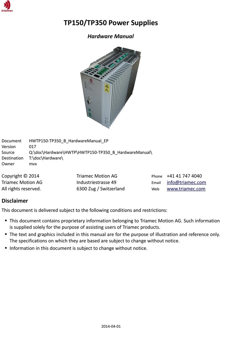
Triamec TP50 User manual

Table of Contents
!"#$
%#&
"'( )
*%# )
+(%,
$ -#.
$ /#.
$# .
$01## .
$ -#
$$ 2/3
$& %/3
$) %/
$, 4,)
$. 4,$
$ 1
$"+(/!
$'+(5
$$1#
$6 3%%#
& 7#8&
& %&
& /&
&$ +(&
&& /)
&) 8/)
) 2'
) 8!"#
)
56
59!
98)$)::97: ;

Safety Informaon
1 Safety Informaon
#!!#
7#207#20#
#<!!
Cauon
Cauon 7#20!
=!#
4
! !
##!!7/
#>!!7#20
!!>
"<
-&;/#7/#!
Danger
Danger ? <
;
Danger
Danger !<#
%
2@ABC
<#
C!D
E7
C
Cauon
Cauon !
#
Cauon
Cauon '2/ ! !
"-#<
98)$)::97: $;

Safety Informaon
Cauon
Cauon 51!
'(!
2 Product Descripon
)<<$$)
%< %$< %$)
F
2#-<
2#!
2(#
'(%/+
%/+
/
3%
##F
!#!'(
#(
D'E
#%/+
"#
#!%/(
!
1
#D$!E
Cauon
Cauon #G5/
"' 7
!
98)$)::97: &;

Product Descripon
2 1 1 Internal or external brake
2(DE'
(D+5E
2 1 2 Phase Fail Detecon
F
HHHF$2/<2/%/
HHH$9F$2/!C#
"<I 1JDK6EB3%JI1
2/3J
2/%/
$2/%/
98)$)::97: );

Product Descripon
2 2 Block Diagram
98)$)::97: ,;
Figure 1: Block Diagram

3 Technical Speci'caons
3 1 Environmental Condions
3 1 1 Transport and storage condions
%< (
%
#$"/,.$D
)L/D$L*EM.L/DM)M/E<!N6)O#E
#"/,.$D
M)L/DM&L*EM&)L/DM$L*E<!))O#E"
!$)L/<
P/Q
3 1 2 General Operang condions
!F"D4,)6E
<D
E!)O)O<#ND,),@E<
M)L/D)L*EM&L/D&L*E
##DR3)/4
,)#E!
S<@##<'<#
!<#<#!
!
98)$)::97: .;

Technical Specicaons
lectrical Specicaons
3 2 Electrical Speci'caons
2-#ML/D)L*EM&L/D&L*E
TP50 TP80 TP130
3-phase or
(1-phase)
AC-Line
input
3-phase AC voltage (L-L) $$)TO &&),TO &&,TO U2/
1-phase AC voltage $$)TO &&),TO &&,TO U2/
Nominal frequency
Nominal maximum AC current IVN
Required external fuse maximum
Power factor correcon
),
<94+4$
9?
2
2
Transformer Requirements "#C
DC-Line
input
Input voltage DC $), , ,$, U%/
Nominal maximum DC current IVN
Required external fuse maximum
&
,
2
2
Line input Internal DC-bus fuse (fast)
In-rush limiter
Insulaon test voltage 1
$
)
$,
2
1
U%/
DC-Bus
output
DC voltage nominal
DC voltage maximum
)
)6
6$
&
&
U
U
Max current (sum)
connuous
pulse 30s
pulse 2s
&
)
2
2
2
Capacitance DC-bus capacitance .)TO *
Internal
brake
resistor
Brake-point UBrake
Adiabac dissipaon energy EA
Connuous power PC
Resistance
).TO
)
)
6TO
)
)
$6TO
)
)
U
K
8
1
External
brake
resistor 2
Min resistance ) & ,) 1
Status/Fan
supply 3
Voltage
Current
&U%/TO
*
U
2
Fan 1, Fan 2 4Direct connecon &U<2
Status out 4High-Side switch &U;B<$2
3!
"'(<(R+((
$ ;*!!"!
& !&U ;*!
98)$)::97: ;

Technical Specicaons
lectrical Specicaons
2-#ML/D)L*EM&L/D&L*E
TP350
3-phase or
(1-phase)
AC-Line
input
3-phase AC voltage (L-L) &&$TO U2/
1-phase AC voltage &&$TO U2/
Nominal frequency
Nominal maximum AC current IVN
Required external fuse maximum
Power factor correcon
),
<94+4$
9?
2
2
Transformer Requirements 4<2
DC-Line
input
Input voltage DC ,$, U%/
Nominal maximum DC current IVN
Required external fuse maximum
&
,
2
2
Line input Internal DC-bus fuse (fast)
In-rush limiter
Insulaon test voltage 1
$
)
$,
2
1
U%/
DC-Bus
output
DC voltage nominal
DC voltage maximum
$)
$
U
U
Max current (sum)
connuous
pulse 30s
pulse 2s
&
)
2
2
2
Capacitance DC-bus capacitance TO *
Internal
brake
resistor
Brake-point UBrake
Adiabac dissipaon energy EA
Connuous power PC
Resistance
$.)TO
)
)
U
K
8
1
External
brake
resistor 2
Min resistance ) 1
Status/Fan
supply 3
Voltage
Current
&U%/TO
*
U
2
Fan 1, Fan 2 4Direct connecon &U<2
Status out 4High-Side switch &U;B<$2
3!
"'(<(R+((
$ ;*!!"!
& !&U ;*!
98)$)::97: 6;

Technical Specicaons
lectrical Specicaons
Cauon
Cauon +"#<
Cauon
Cauon 7'%+!(
/
3 3 AC-Line
2/(
!$D4,)R3&#E
&(2<!D#
4,,6E
(4/ "<
D#ES2"C#
<(&U2/M)O<
!#C"<
* %' %$#CD %E
3 4 DC-Line
"V%/(
3 5 Discharge Currents
Cauon
Cauon %D4).<"/,.))E"!
D5/%E #
(<!+4).1<
##<#
!##
98)$)::97: ;

Technical Specicaons
N 61800-5-1
3 6 EN 61800-5-1
4,)DE<!""" #
4,&U
3 7 EN 61800-3
-4,$/
#
0
0#
5#7/<<!
8<7/-
C*7/#
2/3K,*<2/3
3 8 Overvoltage
2!!!!(#
#8<!
#!!
!(
3 8 1 Internal Brake Capability
!!
!
/W)X/XDRR !E
'<!-!#-!R !
-#
2R+(<(D'E#!
!2!#/"!
98)$)::97: ;

Technical Specicaons
Overvoltage
("B%/
#B'
!'(#
(
3 8 2 External Brake Resistor
#'(!!
'!
"/
3 8 3 Overvoltage Protecon
"'(!<%/+!''
%/! U"
<!!B
'!!
9<B#''
<-!
(2<
!!!
#
3 9 LED Diagnoscs and Status
3%#3%%/+ !
*Y
3%!#
Green LED Red LED Status Output
No line power B B U
Charging DC-Bus Y B U
Ready B &U
One AC-Line missing
(3-Phase Mode only)
Z[ Y U
Line disturbance check (20ms) &U
Line disturbance (1s) U
98)$)::97: ;

Technical Specicaons
L D Diagnoscs and Status
Green LED Red LED Status Output
Discharging DC-Bus Y B U
Brake acve Z[ &U
Overvoltage Y U
Brake open Z[ Y# U
Brake short (*) Z[ Y# U
Over-temperature Z[ Y$# U
Internal error Z[ Y&# U
DXE@#
*F 1;1B
*F 1;1B
98)$)::97: $;

Mounng and Wiring
Mounng and Wiring
4 Mounng and Wiring
!C!("
#
4 1 Dimensions
%F
8 ,6
9 )
% .6
5#
6)
4 2 Cooling
'&L/ 2 $;C
'
4 3 Brake resistor
R!#?!
!! #$
Cauon
Cauon '(
98)$)::97: &;
Figure 2: TP mounng dimensions

Mounng and Wiring
Capacitor reforming
4 4 Capacitor reforming
Cauon
Cauon " !@
@#<C
$)L/
5#F
2&.1;)82!
&<
!)
4 5 Wiring and Connectors
) K" /)&&
98)$)::97: );
Figure 3: TP connecons in case of 1 phase AC supply conguraon
Supply TP50-TP350
Fan 2
DcBusP
DcBusN
L1
L2
L3
PE
PE
24VDC
Ground
solation
Mains
Switch Fuse
Mains
solating
Transformer
L
N
DcBusP
DcBusN
DcBusP
DcBusN
BrakeP
BrakeN
PE
Fan
GND
Fan
GND
24V
GND
Ext. Brake Resistor
DcBusP
DcBusN
Drive 1
Drive 2
Drive 3
Drive 4
Status
GND
Ferrite
DcBusP
DcBusN Drive 5
Fan 1
J6
J5
J10
J11
J7 J9
J0
J1
J2
J3
J4
Controller

Mounng and Wiring
Wiring and Connectors
J0-J4 %/+ 8\((,6$&& )<)!
J5 '( 8\((,6$&&$ )<)!
J6 2/3%/3 8\),.) )<)!
J7 ;*! 8\$&$<<) DE
J9 1 8\,),.<<$) DE
J10 / J11 *<* 8\,),.<<$) DE
PE # 7)D*E 2/3
"%/2/-#<%/3M%/3<4
3;3$
98)$)::97: ,;
Figure 4: TP connecons in case of 3 phase AC supply conguraon
Figure 5: TP connecons in case of DC supply conguraon
Supply TP50-TP350
Fan 2
DcBusP
DcBusN
L1
L2
L3
PE
PE
24VDC
Ground
solation
Fuse
DcBusP
DcBusN
DcBusP
DcBusN
BrakeP
BrakeN
PE
Fan
GND
Fan
GND
24V
GND
Ext. Brake Resistor
DcBusP
DcBusN
Drive 1
Drive 2
Drive 3
Drive 4
Status
GND
DcBusP
DcBusN Drive 5
Fan 1
J6
J5
J10
J11
J7 J9
J0
J1
J2
J3
J4
DC-Supply
DC Line +
DC Line -
Controller
Supply TP50-TP350
Fan 2
DcBusP
DcBusN
L1
L2
L3
PE
PE
24VDC
Ground
solation
Mains
Switch Fuse
Mains
solating
Transformer
L1
L2
L3
DcBusP
DcBusN
DcBusP
DcBusN
BrakeP
BrakeN
PE
Fan
GND
Fan
GND
24V
GND
Ext. Brake Resistor
DcBusP
DcBusN
Drive 1
Drive 2
Drive 3
Drive 4
Status
GND
Ferrite
DcBusP
DcBusN Drive 5
Fan 1
J6
J5
J10
J11
J7 J9
J0
J1
J2
J3
J4
Controller

Mounng and Wiring
Wiring and Connectors
(!7/C
#2/3
Danger
Danger
Must!
Must!
2!-#DE
G
Cauon
Cauon "-#<3
4#
98)$)::97: .;

5 Appendix
5 1 Warranty Informaon
(
-#
#2Triamec Moon AG#
#<#<-4#<'
]!!-#]'!
!
5 2 Service
8>C!"B#!<
/ Triamec Moon AG
Triamec Moon AG
3,
/9,$&+
?
F M&&.&.&&
F ^
8F
98)$)::97: ;

References
Z[ Q0"#_<24&&:0"#:<7#20<
98)$)::97: 6;

Revision History
Version Date Editor Comment
,& *
.& 2%/#
$ 6) 2$
& 66 2(
) /!#
, , 2#8\
. /!!4
< R/%<<<
98)$)::97: ;
/!`
7#20
2
7#20
3,
,$&+; ?
M&&.&.&&
^
8
Disclaimer
a##F
!#7#20 #
!#
'#!
-#!a#
"#a#
This manual suits for next models
3
Table of contents
Other Triamec Power Supply manuals
Popular Power Supply manuals by other brands

fanttik
fanttik EVO300 user manual
IDEATRONIK
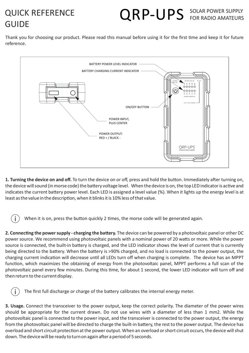
IDEATRONIK QRP-UPS Quick reference guide
Whelen Engineering Company
Whelen Engineering Company CS220 installation guide
VOLTCRAFT
VOLTCRAFT FPPS 9-7.2W operating instructions
Elektro-Automatik
Elektro-Automatik PS 2000 B instruction manual
Akyga
Akyga AK-ND-47 user manual

