XPG PYLON BRONZE Series User manual

QUICK
START
GUIDE
PYLON BRONZE SERIES
POWER SUPPLY
QUICK
START
GUIDE
www.xpg.com
限用物质及其化学符 (Restricted substance and its chemical symbots)
部件名称
Unit
电路板
Circuit Board
电子元器件
Electronic Components
外壳
Case
线材
Cables
风扇
Fan
散热片
Heat Sink
其他辅料
Other Accessories
铅
Pb
汞
Hg
镉
Cd
六价铬
Cr (Vl)
多溴联苯
PBB
多溴 二苯醚
PBDE
超出 0.1wt% 及超出 0.01wt% 系指限用物质之百分比含量超出百分比含量基准值。
Exceeding 0.1wt% and Exceeding 0.01wt% indicate that the percentage content of the restricted substance
exceeds the reference percentage value of presence condition.
: 系指该项限用物质之百分比含量未超出百分比含量基准值。
Indicates that the percentage content of the restricted substance does not exceed the percentage of
reference value of presence.
: 系指该项限用物质為排除項目。
Indicates that the restricted substance corresponds to the exemption.

GAME
TO THE
XTREME
English
Deutsch
Français
Español
Россию
Português
Türkçe
日本の
한국어
简体中文
繁體中文
3
15
27
39
51
63
75
87
99
111
123

03 04
EN
PYLON 750 BRONZE
PYLON 650 BRONZE
PYLON 550 BRONZE
PYLON 450 BRONZE
Installation
Safety and Agency Approvals
5
7
9
11
12
13
Product Specifications
CONGRATULATIONS ON THE PURCHASE OF YOUR NEW
XPG PYLON BRONZE SERIES POWER SUPPLIES
XPG PYLON BRONZE Series power supplies are created for quiet operation while keeping
an Xtreme power Performance. It features a 120mm Fluid-Dynamic Bearing (FDB) fan
running at extremely low RPM with a fan control circuit design that enables a silent and
efficient operation.
80 PLUS BRONZE rated efficiency ensures a low-cost operation and the fixed cable set
provides user convenience with reasonable length and connector quantity. XPG utilizes only
very high quality 105°C Main Japanese capacitors on all units and it’s a great choice for any
high performance PC that are budget conscious.
SAFETY AND PROTECTION
The main outputs will be latched off when each protection is triggered. The main
output can be reset by cycling the DC remote on/off or AC power. +5Vsb output is auto
recovery when fault condition is removed.
INTEGRATED PROTECTION CIRCUITS
Over Current Protection :
XPG has followed Intel Power Supply Design Guide with 110%-140% of total current
on all+12V & +5V & +3.3V rails. Therefore OCP of XPG PYLON is more effective.
Over Voltage Protection :
OVP on +12V, +5V, +3.3V DC outputs rails are required to comply with the latest Intel ATX
Power Supply Design Guide. OVP shuts down the PSU in the event that the DC outputs
exceed a set level, determined by the PSU manufacturer. The minimum voltage levels
required for compliance is +12V rail@ 15.6V max , +5V rail at 7.0V max, +3.3V rail
at 4.5V max.
Over Power Protection :
XPG has followed Intel ATX Power Supply Design Guide with 110-150% of PSU Total
Wattage.
Over Temperature Protection :
OTP ensures that the PSU will shut down when the PSU internal temperature reaches a set
point. This is usually as a result of internal current over loading or a defect fan.
No Load Operation :
XPG has followed Intel ATX Power Supply Design Guide with 0A minimum loading to
support Intel Haswell C6/C7 sleep mode function.
Short Circuit Protection :
SCP is defined as any output impedance of less than 0.1ohms. Amongst other things, SCP
ensures that the PSU shuts down should the +12V, +5V & +3.3V rails short to any ground,
or any other rail. It also ensures that no damage should occur to your PC components if
there is any short circuit inside the system.
XPG Power Supplies have full protection circuits on board to keep your expensive
components safe under all circumstances.

PYLON 750 BRONZE DC cable listing
SPEC Label & Safety Instructions
Packaging content is as follows:
* XPG Pylon Bronze Power Supply Unit
* AC Power Cord
* User Manual
* PSU Screw x 4
Model Number
AC Input
DC Output
Output Current
Output Wattage
Total Continuous Power
Dimension W x L x H
PYLON750BRONZE
+5VSB
2.5A
12.5W
-12V
0.3A
3.6W
+12V
62.5A
750W
750W
+3.3V
20A
+5V
20A
120W
100-240V 10-5A 50-60Hz
150 x 140 x 86mm
Power Supply Fan Curve
Fan speed
2000rpm
1800rpm
1600rpm
1400rpm
1200rpm
1000rpm
800rpm
600rpm
400rpm
10% 30% 40% Typical 60% 70% 80% 90% FullLight
Temp 25°C
Load Condition
05 06
1
1
2
1
2
Qty
Description Connector Per Cable
PCI-E 6+2 Pin x2
Motherboard
20+4 Pin x1
ATX 12V 8 Pin x1
ATX 12V 4+4 Pin x1
SATA x2
Molex x1
Floppy 4 Pin x1
SATA x3
Molex x1
Molex
550mm 150mm 150mm 150mm
SATA SATA SATA
550mm
Floppy 4 Pin
150mm
150mm
150mm
SATA SATA Molex
550mm
650mm
650mm

PYLON 650 BRONZE DC cable listing
SPEC Label & Safety Instructions
Packaging content is as follows:
* XPG Pylon Bronze Power Supply Unit
* AC Power Cord
* User Manual
* PSU Screw x 4
Model Number
AC Input
DC Output
Output Current
Output Wattage
Total Continuous Power
Dimension W x L x H
PYLON650BRONZE
+5VSB
2.5A
12.5W
-12V
0.3A
3.6W
+12V
54A
648W
650W
+3.3V
20A
+5V
20A
110W
100-240V 10-5A 50-60Hz
150 x 140 x 86mm
07 08
Power Supply Fan Curve
Fan speed
1800rpm
1600rpm
1400rpm
1200rpm
1000rpm
800rpm
600rpm
400rpm
200rpm
Load Condition
10% 30% 40% Typical 60% 70% 80% 90% FullLight
Temp 25°C
1
1
2
1
2
Qty
Description Connector Per Cable
PCI-E 6+2 Pin x2
Motherboard
20+4 Pin x1
ATX 12V 8 Pin x1
ATX 12V 4+4 Pin x1
SATA x2
Molex x1
Floppy 4 Pin x1
SATA x3
Molex x1
Molex
550mm 150mm 150mm 150mm
SATA SATA SATA
550mm
Floppy 4 Pin
150mm
150mm
150mm
SATA SATA Molex
550mm
650mm
650mm

1
1
1
1
1
Qty
PYLON 550 BRONZE DC cable listing
SPEC Label & Safety Instructions
Packaging content is as follows:
* XPG Pylon Bronze Power Supply Unit
* AC Power Cord
* User Manual
* PSU Screw x 4
Model Number
AC Input
DC Output
Output Current
Output Wattage
Total Continuous Power
Dimension W x L x H
PYLON550BRONZE
+5VSB
2.5A
12.5W
-12V
0.3A
3.6W
+12V
45.5A
546W
550W
+3.3V
20A
+5V
20A
110W
100-240V 8-4A 50-60Hz
150 x 140 x 86mm
Description
09 10
Power Supply Fan Curve
Fan speed
1800rpm
1600rpm
1400rpm
1200rpm
1000rpm
800rpm
600rpm
400rpm
200rpm
Load Condition
10% 30% 40% Typical 60% 70% 80% 90% FullLight
PCI-E 6+2 Pin x2
SATA x2
Molex x1
Floppy 4 Pin x1
SATA x3
Molex x1
Molex
550mm 150mm 150mm 150mm
SATA SATA SATA
550mm
Floppy 4 Pin
150mm
150mm
150mm
SATA SATA Molex
550mm
650mm
650mm
Temp 25°C
Connector Per Cable
Motherboard
20+4 Pin x1
ATX 12V 4+4 Pin x1

PYLON 450 BRONZE DC cable listing
SPEC Label & Safety Instructions
Packaging content is as follows:
* XPG Pylon Bronze Power Supply Unit
* AC Power Cord
* User Manual
* PSU Screw x 4
Model Number
AC Input
DC Output
Output Current
Output Wattage
Total Continuous Power
Dimension W x L x H
PYLON450BRONZE
+5VSB
2.5A
12.5W
-12V
0.3A
3.6W
+12V
37.5A
450W
450W
+3.3V
20A
+5V
20A
100W
100-240V 7A-3.5A 50-60Hz
150 x 140 x 86mm
11 12
Fan speed
1800rpm
1600rpm
1400rpm
1200rpm
1000rpm
800rpm
600rpm
400rpm
200rpm
Load Condition
10% 30% 40% Typical 60% 70% 80% 90% FullLight
Power Supply Fan Curve
Temp 25°C
1
1
1
1
1
Qty
Description
PCI-E 6+2 Pin x2
Motherboard
20+4 Pin x1
ATX 12V 4+4 Pin x1
SATA x2
Molex x1
Floppy 4 Pin x1
SATA x3
Molex x1
Molex
550mm 150mm 150mm 150mm
SATA SATA SATA
550mm
Floppy 4 Pin
150mm
150mm
150mm
SATA SATA Molex
550mm
650mm
650mm
Connector Per Cable

INSTALLING YOUR NEW PYLON POWER SUPPLY
1. Remove the power supply from its packaging.
2. Install the PSU into the case with the four screws provided.
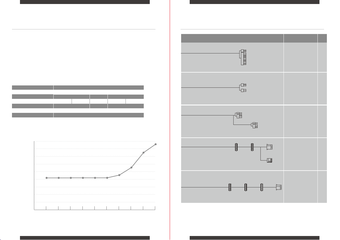
3. Connect the 24pin ATX cable to the motherboard 24pin power socket.
4. Connect the EPS 12V 8 / 4+4pin cable to the CPU power socket.
5. Connect SATA power cables to any devices that may use 4-pin peripheral connectors, i.e. hard drives, solid state
drives, optical drives.
6. Connect the corresponding PCI-E connector as instructed by your graphic card’s user manual, if your graphic card
requires additional PCI-E power.
Please note that the power supply utilizes a 6+2pin PCI-E connector that can be effectively used either as a single
8pin or a 6pin PCI-E connector.
To use it as a 6pin PCI-E connector, please detach the 2pin connector portion from the connector header.
7. Connect the peripheral/floppy disk 4pin connector for fans, pumps, legacy components and other devices/adaptors.
8. Connect the AC Power cord to both your power supply and to the wall.
Check all connections to ensure that every item is properly plugged in and turn the power switch of the power supply
to the ON position.
Make sure that your system is turned off and unplugged before you start installing it.
Disconnect the AC power cord from your old power supply if any.
TROUBLESHOOTING
1. Please make sure the AC main power cord is connected to your PC correctly and that your power outlet is properly
emitting power.
2. Please make sure the AC On/Off switch on the back panel of the power supply unit in the “I” (On) position.
3. Please make sure that the MB& CPU Power Socket & connectors are connected correctly on the motherboard.
4. If you still have problem turning on your PC, please contact ADATA Tech Support, Service Center or your local dealer.
If your system does not turn on after installing the power supply, please follow the
troubleshooting guide listed below:
DURATION OF WARRANTY
ADATA Technology Co., Ltd. provides a 3 years warranty period for this product unless
regional laws and regulations state otherwise.
13 14
1. The warranty label is altered, damaged or missing.
2. Product serial number does not conform to our original system.
3. Product was purchased from an unauthorized agent.
4. Damage caused by natural calamity
5. Any abuse outside the intended product operation.
LIMITATION OF WARRANTY
This limited warranty covers only repairs or replacements of products manufactured by
ADATA Technology Co. Ltd. and its authorized partners.
Please note that ADATA is responsible for providing free repairs except for the following
reasons:
ONLINE CUSTOMER SERVICE
For frequently askeatd questions, additional information and service instruction please visit
our product page www.xpg.com
IMPORTANT SAFETY INFORMATION
1. NEVER, under any circumstances, open the power supply unit or attempt to repair it by yourself. This is extremely
dangerous due to the high voltage components inside.
2. DO NOT insert any object into the fan grill or the ventilation area of the power supply unit.
3. DO NOT place any object in front of the fan or the ventilation area of the power supply unit that may obstruct or
restrict airflow.
4. USE the included cable with the power supply unit. or as purchased from XPG. DO NOT use any third party cables
or extension cables with this unit.
5. Avoid dust, humidity, and temperature extremes. Do not place the power supply unit in any area where it may
become wet.
6. The power supply unit is for integration into a computer, and not intended for external or outdoor usage.
7. Failure to comply with any manufacturer instructions and/or any of these safety instructions may result void
warranties and guarantees.
Agency
CE
CB
FCC (IC)
EAC
CCC
TUV
cTUVus
TUV-S
RCM
NOM
BSMI
KC
ROHS 2.0
WEEE
Standard
SAFETY AND AGENCY APPROVALS
EN55032:2015, EN55035:2017, EN55024:2010+A1:2015
EN61000-3-2:2014, EN61000-3-3:2013
IEC 62368-1:2014 (Second Edition)
IEC 60950-1:2005 (Second Edition) + Am 1:2009 + Am 2:2013
TP TC 004/2011
TP TC 020/2011
UL 62368-1:2014
CAN/CSA-C22.2 No. 62368-1-14
IEC 62368-1:2014, US-TUVR-011828,
US-TUVR-011851, US-TUVR-011833
CNS15663第五節(102), CNS13438 (95), CNS14336-1 (99)
FCC Part 15 Subpart B Class B:2019
ICES-003 Issue 6:2016
ANSI C63.4:2014
GB4943.1-2011, GB17625.1-2012, GB/T9254-2008
EN 62368-1:2014
IEC 62368-1:2014
NOM-001-SCFI-1993
K60950-1 (2011-12)
2011/65/EU &2015/863/EU, Restriction of Hazardous Substances
Directive
2012/19/EU Waste electrical and electronic equipment Directive

15 16
DE
PYLON 750 BRONZE
PYLON 650 BRONZE
PYLON 550 BRONZE
PYLON 450 BRONZE
Installation
17
19
21
23
25
Produktspezifikationen
HERZLICHEN GLÜCKWUNSCH ZUM KAUF IHRES NEUEN
NETZTEIL DES XPG-PYLON-BRONZE-SERIE
Netzteile der XPG-PYLON-BRONZE-Serie sind auf lautlosen Betrieb ausgelegt, während Xtreme-Leistung
gewahrt wird. Sie verfügen über einen 120 mm großen Fluid-Dynamic-Bearing- (FDB) Lüfter mit extrem
geringen U/min und einer Lüftersteuerung, die lautlosem, effizienten Betrieb gewährleistet.
Gemäß 80 PLUS BRONZE bewertete Effizienz gewährleistet einen kostengünstigen Betrieb und ein fester
Kabelsatz bietet Nutzerkomfort mit angemessener Länge und Anschlussquantität. XPG nutzt bei allen
Geräten ausschließlich sehr hochwertige japanische Hauptkondensatoren, die 105 °C standhalten. Sie sind
kostengünstig und eine großartige Wahl für jeden leistungsfähigen PC.
SICHERHEIT UND SCHUTZ
Die Hauptausgabe wird unterbrochen, sobald ein Schutz auslöst. Die Stromausgabe kann durch Aus- und
Wiedereinschalten der Gleichspannungsfernbedienung oder Netzstromversorgung zurückgesetzt werden. Die
Ausgabe von +5 Vsb ist auf automatische Wiederherstellung bei Beseitigung des Fehlerzustands eingestellt.
INTEGRIERTE SCHUTZBESCHALTUNG
Überstromschutz:
XPG hat die Intel-Netzteil-Designanleitung mit 110 bis 140 % des gesamten Stroms an allen Schienen mit
+12 V, +5 V und +3,3 V befolgt. Daher ist der Überstromschutz von XPG PYLON effektiver.
Überspannungsschutz:
Überspannungsschutz an den Ausgangsschienen mit +12 V, +5 V und +3,3 V ist zur Einhaltung der
aktuellsten Intel-ATX-Netzteil-Designanleitung erforderlich. Überspannungsschutz schaltet das Netzteil ab,
wenn die Gleichspannungsausgabe ein vom Netzteilhersteller festgelegtes Niveau überschreitet. Mindestens
erforderliche Spannungsniveaus für Konformität: Schiene +12 V bei max. 15,6 V, Schiene +5 V bei max. 7,0
V, Schiene +3,3 V bei max. 4,5 V.
Überlastungsschutz:
XPG hat die Intel-ATX-Netzteil-Designanleitung mit 110 bis 150 % gesamte Netzteilleistung befolgt.
Überhitzungsschutz:
Überhitzungsschutz stellt sicher, dass sich das Netzteil abschaltet, sobald die Temperatur im Netzteil einen
festgelegten Punkt erreicht. Dies geschieht üblicherweise durch eine interne Stromüberlastung oder einen
defekten Lüfter.
Lastfreier Betrieb:
XPG hat die Intel-ATX-Netzteil-Designanleitung mit einer minimalen Last von 0 A befolgt, um den
Ruhezustand von Intel Haswell C6/C7 zu unterstützen.
Kurzschlussschutz:
Kurzschlussschutz ist als Ausgangsimpedanz von weniger als 0,1 Ohm definiert. Unter anderem
gewährleistet Kurzschlussschutz eine Abschaltung des Netzteils, falls bei den Schienen +12 V, +5 V und
+3,3 V aus irgendeinem Grund oder mit irgendeiner anderen Schiene ein Kurzschluss auftritt. Zudem
gewährleistet er, dass Ihre PC-Komponenten bei einem Kurzschluss im System keinen Schaden nehmen.
XPG-Netzteile haben vollständige Schutzbeschaltung, damit Ihre teuren Komponenten unter allen Umständen
keinem Risiko ausgesetzt werden.
Sicherheits- und
Behördenzulassungen
26

1
Beschreibung
PYLON 750 BRONZE Gleichspannungskabelauflistung
Lieferumfang ist wie folgt:
* XPG-Pylon-Bronze-Netzteil
* Wechselspannungskabel
* Bedienungsanleitung
* Netzteilschraube x 4
PYLON750BRONZE
+5VSB
2,5A
12,5W
-12V
0,3A
3,6W
+12V
62,5A
750W
750W
+3,3V
20A
+5V
20A
120W
100-240V 10-5A 50-60Hz
150 x 140 x 86mm
Netzteil-Lüfterkurve
Lüftergeschwindigkeit
2000rpm
1800rpm
1600rpm
1400rpm
1200rpm
1000rpm
800rpm
600rpm
400rpm
10% 30% 40% Typical 60% 70% 80% 90% FullLight
Load Condition
17 18
1
1
2
1
2
Anzahl
Beschreibung Anschluss
Molex
550mm 150mm 150mm 150mm
SATA SATA SATA
550mm
Diskettenlaufwerk, 4-polig
150mm
150mm
150mm
SATA SATA Molex
550mm
650mm
650mm
ATX-Kabel,
24-polig x1
PCI-E-Kabel,
8-polig (6 + 2)
SATA-Kabel,
5-polig
Molex x1
Diskettenlaufwerk-
skabel, 4-polig
SATA-Kabel,
5-polig
Molex x1
Temp 25°C
ATX-12-V-Kabel,
8-polig x1
ATX-12-V-Kabel,
4 + 4-polig x1
Modellnummer
Wechselspannungseingang
Gleichspannungsausgang
Ausgangsstrom
Ausgangsleistung
Kontinuierliche Leistung gesamt
Abmessungen B x L x H
Technische Daten und Sicherheitshinweise

PYLON 650 BRONZE Gleichspannungskabelauflistung
Lieferumfang ist wie folgt:
* XPG-Pylon-Bronze-Netzteil
* Wechselspannungskabel
* Bedienungsanleitung
* Netzteilschraube x 4
PYLON650BRONZE
+5VSB
2,5A
12,5W
-12V
0,3A
3,6W
+12V
54A
648W
650W
+3,3V
20A
+5V
20A
110W
100-240V 10-5A 50-60Hz
150 x 140 x 86mm
19 20
Netzteil-Lüfterkurve
Lüftergeschwindigkeit
1800rpm
1600rpm
1400rpm
1200rpm
1000rpm
800rpm
600rpm
400rpm
200rpm
Load Condition
10% 30% 40% Typical 60% 70% 80% 90% FullLight
Anzahl
Beschreibung Anschluss
Molex
550mm 150mm 150mm 150mm
SATA SATA SATA
550mm
Diskettenlaufwerk, 4-polig
150mm
150mm
150mm
SATA SATA Molex
550mm
650mm
650mm
ATX-Kabel,
24-polig x 1
PCI-E-Kabel,
8-polig (6 + 2)
SATA-Kabel,
5-polig
Molex x1
Diskettenlaufwerk-
skabel, 4-polig
SATA-Kabel,
5-polig
Molex x1
Temp 25°C
11
1
2
1
2
ATX-12-V-Kabel,
8-polig x 1
ATX-12-V-Kabel,
4 + 4-polig x 1
Modellnummer
Wechselspannungseingang
Gleichspannungsausgang
Ausgangsstrom
Ausgangsleistung
Kontinuierliche Leistung gesamt
Abmessungen B x L x H
Technische Daten und Sicherheitshinweise

Beschreibung
1
1
1
1
1
Anzahl
PYLON 550 BRONZE Gleichspannungskabelauflistung
Lieferumfang ist wie folgt:
* XPG-Pylon-Bronze-Netzteil
* Wechselspannungskabel
* Bedienungsanleitung
* Netzteilschraube x 4
PYLON550BRONZE
+5VSB
2,5A
12,5W
-12V
0,3A
3,6W
+12V
45,5A
546W
550W
+3,3V
20A
+5V
20A
110W
100-240V 8-4A 50-60Hz
150 x 140 x 86mm
Beschreibung Anschluss
21 22
Netzteil-Lüfterkurve
Lüftergeschwindigkeit
1800rpm
1600rpm
1400rpm
1200rpm
1000rpm
800rpm
600rpm
400rpm
200rpm
Load Condition
10% 30% 40% Typical 60% 70% 80% 90% FullLight
Molex
550mm 150mm 150mm 150mm
SATA SATA SATA
550mm
Diskettenlaufwerk, 4-polig
150mm
150mm
150mm
SATA SATA Molex
550mm
650mm
650mm
ATX-Kabel,
24-polig x 1
PCI-E-Kabel,
8-polig (6 + 2)
SATA-Kabel,
5-polig
Molex x1
Diskettenlaufwerk-
skabel, 4-polig
SATA-Kabel,
5-polig
Molex x1
Temp 25°C
ATX-12-V-Kabel,
4 + 4-polig x 1
Modellnummer
Wechselspannungseingang
Gleichspannungsausgang
Ausgangsstrom
Ausgangsleistung
Kontinuierliche Leistung gesamt
Abmessungen B x L x H
Technische Daten und Sicherheitshinweise

PYLON 450 BRONZE Gleichspannungskabelauflistung
Technische Daten und Sicherheitshinweise
Lieferumfang ist wie folgt:
* XPG-Pylon-Bronze-Netzteil
* Wechselspannungskabel
* Bedienungsanleitung
* Netzteilschraube x 4
Modellnummer
Wechselspannungseingang
Gleichspannungsausgang
Ausgangsstrom
Ausgangsleistung
Kontinuierliche Leistung gesamt
Abmessungen B x L x H
PYLON450BRONZE
+5VSB
2,5A
12,5W
-12V
0,3A
3,6W
+12V
37,5A
450W
450W
+3,3V
20A
+5V
20A
100W
100-240V 7A-3.5A 50-60Hz
150 x 140 x 86mm
23 24
Anzahl
Beschreibung Anschluss
Lüftergeschwindigkeit
1800rpm
1600rpm
1400rpm
1200rpm
1000rpm
800rpm
600rpm
400rpm
200rpm
Load Condition
10% 30% 40% Typical 60% 70% 80% 90% FullLight
Netzteil-Lüfterkurve
1
1
1
1
1
Molex
550mm 150mm 150mm 150mm
SATA SATA SATA
550mm
Diskettenlaufwerk, 4-polig
150mm
150mm
150mm
SATA SATA Molex
550mm
650mm
650mm
ATX-Kabel,
24-polig x 1
PCI-E-Kabel,
8-polig (6 + 2)
SATA-Kabel,
5-polig
Molex x1
Diskettenlaufwerk-
skabel, 4-polig
SATA-Kabel,
5-polig
Molex x1
Temp 25°C
ATX-12-V-Kabel,
4 + 4-polig x 1

25 26
IHR NEUES PYLON-NETZTEIL INSTALLIEREN
1. Nehmen Sie das Netzteil aus seiner Verpackung.
2. Installieren Sie das Netzteil mit den vier mitgelieferten Schrauben im Gehäuse.
3. Verbinden Sie das 24-polige ATX-Kabel mit dem 24-poligen Stromanschluss des Motherboards.
4. Verbinden Sie das EPS-12V 8 / 4+4-Pin-Kabel mit dem CPU-Stromascnluss.
5. Verbinden Sie SATA-Kabel mit allen Geräten, die 4-polige Peripherieanschlüsse nutzen können, z. B. Festplatten,
Solid State Drives, optische Laufwerke.
6. Verbinden Sie den entsprechenden PCI-E-Anschluss entsprechend den Anweisungen der Bedienungsanleitung Ihrer
Grafikkarte, falls Ihre Grafikkarte zusätzliche PCI-E-Stromversorgung erfordert.
Bitte beachten Sie, dass das Netzteil einen 6+2-Pin-PCI-E-Anschluss nutzt, der effektiv als einzelner 8-poliger oder
6-poliger PCI-E-Anschluss genutzt werden kann.
Verwenden Sie ihn als 6-poligen PCI-E-Anschluss, indem Sie den 2-poligen Anschlussabschnitt von der Stiftleiste
trennen.
7. Verbinden Sie den 4-poligen Anschluss von Peripherie/Diskettenlaufwerk für Lüfter, Pumpen, veraltete Komponenten
und andere Geräte/Adapter.
8. Verbinden Sie das Netzkabel mit Ihrem Netzteil und einer Steckdose.
Prüfen Sie alle Verbindungen, um sicherzustellen, dass alles richtig angeschlossen ist, drehen Sie dann den
Ein-/Ausschalter des Netzteils in die Ein-Position.
Stellen Sie sicher, dass Ihr System abgeschaltet und getrennt ist, bevor Sie mit der
Installation beginnen.
Trennen Sie das Netzkabel von Ihrem alten Netzteil, falls vorhanden.
PROBLEMLÖSUNG
1. Vergewissern Sie sich, dass das Netzkabel richtig an Ihren PC angeschlossen ist und Ihre Steckdose funktioniert.
2. Prüfen Sie, ob der Ein-/Ausschalter an der Rückblende des Netzteils auf die Position „I“ (eingeschaltet) eingestellt ist.
3. Vergewissern Sie sich, dass Stromanschlüsse von MB und CPU richtig am Motherboard angeschlossen sind.
4. Falls weiterhin Probleme beim Einschalten Ihres PCs auftreten, wenden Sie sich bitte an ADATAs technischen
Support, den Kundendienst oder Ihren örtlichen Händler.
Falls sich Ihr System nach Installation des Netzteils nicht einschaltet, befolgen Sie die
nachstehende Anleitung zur Fehlerbehebung:
GARANTIEDAUER
ADATA Technology Co., Ltd. bietet eine 3-jährige Garantiedauer für dieses Produkt, sofern
nicht von regionalen Gesetzen und Vorschriften anders verlangt.
1. Das Garantieetikett wurde verändert, beschädigt oder fehlt.
2. Produktseriennummer stimmt nicht mit unserem ursprünglichen System überein.
3. Produkt wurde bei einem unautorisierten Händler erworben.
4. Schäden aufgrund von Naturkatastrophen.
5. Missbrauch bzw. Verwendung unter Nichtbeachtung der Bedienungsanweisungen.
GARANTIEBESCHRÄNKUNG
Diese eingeschränkte Garantie deckt nur Reparaturen oder Auswechslungen von durch
ADATA Technology Co. Ltd. und seine autorisierten Partner ab.
Bitte beachten Sie, dass ADATA für die Bereitstellung kostenloser Reparaturen verantwortlich
ist, mit folgenden Ausnahmen:
ONLINE-KUNDENDIENST
Bei häufig gestellten Fragen finden Sie zusätzliche Informationen und Serviceanweisungen
auf unserer Produktseite unter www.xpg.com
WICHTIGE SICHERHEITSHINWEISE
1. Öffnen Sie NIEMALS das Netzteil, versuchen Sie unter keinen Umständen, das Netzteil zu reparieren. Dies ist
aufgrund der hohen Spannung von Komponenten im Inneren extrem gefährlich.
2. Stecken Sie KEINE Gegenstände in das Lüftergitter oder den Belüftungsbereich des Netzteils.
3. Platzieren Sie NICHTS vor dem Lüfter oder Belüftungsbereich des Netzteils, das den Luftstrom blockieren oder
einschränken könnte.
4. VERWENDEN Sie das mit dem Netzteil gelieferte oder bei XPG erworbene Kabel. Verwenden Sie KEINE
Drittanbieterkabel oder Verlängerungskabel mit diesem Gerät.
5. Vermeiden Sie Staub, Feuchtigkeit und extreme Temperaturen. Platzieren Sie das Netzteil nicht an einem Ort, an
dem es feucht werden könnte.
6. Das Netzteil ist für den Einbau in einem Computer vorgesehen. Es eignet sich nicht für externe Nutzung oder eine
Nutzung im Freien.
7. Bei Nichteinhaltung der Herstelleranweisungen und/oder Sicherheitshinweise erlöschen Garantien und
Gewährleistungen.
SICHERHEITS- UND BEHÖRDENZULASSUNGEN
Behörde
CE
CB
FCC (IC)
EAC
CCC
TUV
cTUVus
TUV-S
RCM
NOM
BSMI
KC
ROHS 2.0
WEEE
Standard
EN55032:2015, EN55035:2017, EN55024:2010+A1:2015
EN61000-3-2:2014, EN61000-3-3:2013
IEC 62368-1:2014 (Second Edition)
IEC 60950-1:2005 (Second Edition) + Am 1:2009 + Am 2:2013
TP TC 004/2011
TP TC 020/2011
UL 62368-1:2014
CAN/CSA-C22.2 No. 62368-1-14
IEC 62368-1:2014, US-TUVR-011828,
US-TUVR-011851, US-TUVR-011833
CNS15663第五節(102), CNS13438 (95), CNS14336-1 (99)
FCC Part 15 Subpart B Class B:2019
ICES-003 Issue 6:2016
ANSI C63.4:2014
GB4943.1-2011, GB17625.1-2012, GB/T9254-2008
EN 62368-1:2014
IEC 62368-1:2014
NOM-001-SCFI-1993
K60950-1 (2011-12)
2011/65/EU &2015/863/EU, Restriction of Hazardous Substances
Directive
2012/19/EU Waste electrical and electronic equipment Directive

Agréments de sécurité
et d’agences
27 28
FR
PYLON 750 BRONZE
PYLON 650 BRONZE
PYLON 550 BRONZE
PYLON 450 BRONZE
Installation
29
31
33
35
37
Spécifications du produit
FÉLICITATIONS POUR L’ACHAT DE VOTRE NOUVEAU BLOC
D’ALIMENTATION XPG PYLON BRONZE SERIES
Les blocs d'alimentation XPG PYLON BRONZE Series sont créés pour un fonctionnement silencieux tout en
conservant une performance d'alimentation Xtreme. Ils disposent d'un ventilateur à roulement dynamique
fluide (FDB) de 120 mm tournant à un régime extrêmement bas avec un circuit de commande de ventilateur
permettant un fonctionnement silencieux et efficace.
L'efficacité classée 80 PLUS BRONZE garantit un fonctionnement à faible coût et le jeu de câbles fixes offre
un confort d'utilisation avec une longueur et une quantité de connecteur raisonnables. XPG utilise
exclusivement des condensateurs principal japonais 105°C de très haute qualité sur tous les blocs et c'est un
excellent choix pour tout PC de hautes performances à budget contenu.
SÉCURITÉ ET PROTECTION
Les sorties principales sont verrouillées lors du déclenchement de chaque protection. La sortie principale peut
être réinitialisée en allumant et en éteignant successivement le CC distant ou l’alimentation secteur. La sortie
+5Vsb est réglée sur une récupération automatique lorsque la condition de défaillance est éliminée.
CIRCUITS DE PROTECTION INTÉGRÉS
Protection contre les surintensités (OCP) :
XPG a respecté le Guide Intel de conception des blocs d’alimentation avec 110% à 140% du courant total sur
tous les rails +12V, +5V et +3,3V. L'OCP de XPG PYLON est donc plus efficace.
Protection contre les surtensions (OVP) :
L’OVP sur les rails de sortie CC +12V, +5V et +3,3V est nécessaire pour se conformer au Guide Intel ATX de
conception des blocs d'alimentation ATX. L’OVP arrête le bloc d’alimentation dans le cas où les sorties CC
dépassent un niveau donné, déterminé par le fabricant du bloc d’alimentation. Les niveaux de tension
minimum requis pour la conformité sont les suivants: rail +12 V à 15,6 V maxi, rail + 5 V à 7,0 V maxi, rail +
3,3 V à 4,5V maxi.
Protection contre les surcharges :
XPG a respecté le Guide Intel de conception des blocs d’alimentation ATX avec 110% à 150% de la puissance
totale du bloc d’alimentation.
Protection contre la surchauffe (OTP) :
L’OTP s’assure que le bloc d’alimentation s'éteigne lorsque sa température interne atteint un niveau donné.
Ceci est généralement dû à une surcharge de courant interne ou à un ventilateur défectueux.
Fonctionnement à vide :
XPG a suivi le Guide Intel de conception des blocs alimentations ATX avec une charge minimale de 0 A pour
prendre en charge la fonction de mode de veille Intel Haswell C6/C7.
Protection contre les courts-circuits (SCP) :
La SCP réagit à toute impédance de sortie inférieure à 0,1 ohms. Entre autres choses, la SCP s’assure que
l’alimentation est coupée en cas de court-circuit des rails + 12V, + 5V ou + 3,3V par rapport à une masse ou
à un autre rail. Elle garantit également que les composants de votre PC ne subiront aucun dommage en cas
de court-circuit dans le système.
Les alimentations XPG disposent de circuits de protection complets afin de protéger vos composants coûteux
en toutes circonstances.
38

PYLON 750 BRONZE Listing des câbles CC
Étiquette de SPÉC et instructions relatives à la sécurité
Le contenu de l'emballage est le suivant :
* Bloc d'alimentation XPG Pylon Bronze
* Cordon d'alimentation CA
* Manuel d’utilisation
* Vis de bloc d’alimentation x 4
Numéro de modèle
Entrée secteur
Sortie CC
Courant de sortie
Puissance de sortie
Puissance continue totale
Dimensions L x l x H
PYLON750BRONZE
+5VSB
2,5A
12,5W
-12V
0,3A
3,6W
+12V
62,5A
750W
750W
+3,3V
20A
+5V
20A
120W
100-240V 10-5A 50-60Hz
150 x 140 x 86mm
Courbe du ventilateur d'alimentation
Vitesse du ventilateur
2000rpm
1800rpm
1600rpm
1400rpm
1200rpm
1000rpm
800rpm
600rpm
400rpm
10% 30% 40% Typical 60% 70% 80% 90% FullLight
Load Condition
29 30
1
1
2
1
2
Qté
Description Connecteur
Molex
550mm 150mm 150mm 150mm
SATA SATA SATA
550mm
FLOPPY 4 broches
150mm
150mm
150mm
SATA SATA Molex
550mm
650mm
650mm
Câble ATX 24
broches x 1
Câble ATX 12V
8 broches x 1
Câble ATX 12V
4+4 broches x 1
Câble PCI-e 8
broches (6+2)
Câble SATA 5
broches
Molex x1
Câble SATA 5
broches
Molex x1
Câble FLOPPY
4 broches
Temp 25°C

PYLON 650 BRONZE Listing des câbles CC
Étiquette de SPÉC et instructions relatives à la sécurité
Le contenu de l'emballage est le suivant :
* Bloc d'alimentation XPG Pylon Bronze
* Cordon d'alimentation CA
* Manuel d’utilisation
* Vis de bloc d’alimentation x 4
Numéro de modèle
Entrée secteur
Sortie CC
Courant de sortie
Puissance de sortie
Puissance continue totale
Dimensions L x l x H
PYLON650BRONZE
+5VSB
2,5A
12,5W
-12V
0,3A
3,6W
+12V
54A
648W
650W
+3,3V
20A
+5V
20A
110W
100-240V 10-5A 50-60Hz
150 x 140 x 86mm
31 32
Courbe du ventilateur d'alimentation
Vitesse du ventilateur
1800rpm
1600rpm
1400rpm
1200rpm
1000rpm
800rpm
600rpm
400rpm
200rpm
Load Condition
10% 30% 40% Typical 60% 70% 80% 90% FullLight
1
1
2
1
2
Qté
Description Connecteur
Molex
550mm 150mm 150mm 150mm
SATA SATA SATA
550mm
FLOPPY 4 broches
150mm
150mm
150mm
SATA SATA Molex
550mm
650mm
650mm
Câble PCI-e 8
broches (6+2)
Câble SATA 5
broches
Molex x1
Câble SATA 5
broches
Molex x1
Câble FLOPPY
4 broches
Câble ATX 24
broches x 1
Câble ATX 12V
8 broches x 1
Câble ATX 12V
4+4 broches x 1
Temp 25°C

1
1
1
1
1
Qté
PYLON 550 BRONZE Listing des câbles CC
Étiquette de SPÉC et instructions relatives à la sécurité
Le contenu de l'emballage est le suivant :
* Bloc d'alimentation XPG Pylon Bronze
* Cordon d'alimentation CA
* Manuel d’utilisation
* Vis de bloc d’alimentation x 4
Numéro de modèle
Entrée secteur
Sortie CC
Courant de sortie
Puissance de sortie
Puissance continue totale
Dimensions L x l x H
PYLON550BRONZE
+5VSB
2,5A
12,5W
-12V
0,3A
3,6W
+12V
45,5A
546W
550W
+3,3V
20A
+5V
20A
110W
100-240V 8-4A 50-60Hz
150 x 140 x 86mm
Description Connecteur
33 34
Courbe du ventilateur d'alimentation
Vitesse du ventilateur
1800rpm
1600rpm
1400rpm
1200rpm
1000rpm
800rpm
600rpm
400rpm
200rpm
Load Condition
10% 30% 40% Typical 60% 70% 80% 90% FullLight
Molex
550mm 150mm 150mm 150mm
SATA SATA SATA
550mm
FLOPPY 4 broches
150mm
150mm
150mm
SATA SATA Molex
550mm
650mm
650mm
Câble ATX 24
broches x 1
Câble ATX 12V
4+4 broches x 1
Câble PCI-e 8
broches (6+2)
Câble SATA 5
broches
Molex x1
Câble SATA 5
broches
Molex x1
Câble FLOPPY
4 broches
Temp 25°C

PYLON 450 BRONZE Listing des câbles CC
Étiquette de SPÉC et instructions relatives à la sécurité
Le contenu de l'emballage est le suivant :
* Bloc d'alimentation XPG Pylon Bronze
* Cordon d'alimentation CA
* Manuel d’utilisation
* Vis de bloc d’alimentation x 4
Numéro de modèle
Entrée secteur
Sortie CC
Courant de sortie
Puissance de sortie
Puissance continue totale
Dimensions L x l x H
PYLON450BRONZE
+5VSB
2,5A
12,5W
-12V
0,3A
3,6W
+12V
37,5A
450W
450W
+3,3V
20A
+5V
20A
100W
100-240V 7A-3.5A 50-60Hz
150 x 140 x 86mm
35 36
Qté
Description Connecteur
Vitesse du ventilateur
1800rpm
1600rpm
1400rpm
1200rpm
1000rpm
800rpm
600rpm
400rpm
200rpm
Load Condition
10% 30% 40% Typical 60% 70% 80% 90% FullLight
Courbe du ventilateur d'alimentation
1
1
1
1
1
Molex
550mm 150mm 150mm 150mm
SATA SATA SATA
550mm
FLOPPY 4 broches
150mm
150mm
150mm
SATA SATA Molex
550mm
650mm
650mm
Câble PCI-e 8
broches (6+2)
Câble SATA 5
broches
Molex x1
Câble SATA 5
broches
Molex x1
Câble FLOPPY
4 broches
Temp 25°C
Câble ATX 24
broches x 1
Câble ATX 12V
4+4 broches x 1

INSTALLATION DE VOTRE NOUVELLE ALIMENTATION PYLON
1. Sortez le bloc d'alimentation de son emballage.
2. Installez le bloc d'alimentation dans le boîtier avec les quatre vis fournies.
3. Branchez le câble ATX 24 broches sur la prise d'alimentation 24 broches de la carte mère.
4. Connectez le câble EPS 12V 8 / 4+4 broches à la prise d'alimentation du CPU.
5. Raccordez les câbles d'alimentation SATA à tous les dispositifs pouvant utiliser des connecteurs périphériques à 4
broches, c'est-à-dire les disques durs, les SSD, les lecteurs optiques.
6. Branchez le connecteur PCI-E correspondant comme indiqué dans le manuel d'utilisation de votre carte graphique,
si votre carte graphique requiert une alimentation PCI-E dédiée.
Veuillez noter que l'alimentation utilise un connecteur PCI-E 6+2 broches qui peut servir effectivement de
connecteur PCI-E 8 broches ou 6 broches.
Pour l'utiliser comme connecteur PCI-E 6 broches, veuillez détacher la partie connecteur 2 broches de la tête du
connecteur.
7. Raccordez le connecteur périphérique / floppy (disquette) à 4 broches pour les ventilateurs, les pompes, les
composants anciens et les autres périphériques / adaptateurs.
8. Raccordez le cordon d'alimentation CA secteur à votre bloc d'alimentation et à la prise secteur.
Vérifiez tous les branchements pour vous assurer que chaque élément est correctement raccordé et mettez
l'interrupteur d'alimentation de l'alimentation en position MARCHE.
Assurez-vous que votre système est éteint et débranché avant de démarrer l’installation.
Débranchez le cordon d'alimentation CA secteur de votre ancien bloc d'alimentation, le
cas échéant.
DÉPANNAGE
1. Veuillez vous assurer que le cordon d'alimentation secteur est correctement connecté à votre PC et que votre prise
de courant fournit correctement du courant.
2. Veuillez vous assurer que l'interrupteur secteur Marche / Arrêt situé sur le panneau arrière du bloc d'alimentation
est en position « I » (Marche).
3. Veuillez vous assurer que la prise et les connecteurs d'alimentation de la carte mère et du CPU sont correctement
raccordés à la carte mère.
4. Si vous avez toujours des problèmes pour allumer votre PC, veuillez contacter l’assistance technique ADATA, le
centre de service ou votre revendeur local.
1. L'étiquette de garantie a été altérée, endommagée ou enlevée.
2. Le numéro de série du produit n'est pas conforme à notre système original.
3. Le produit a été acheté auprès d'un agent non autorisé.
4. Les dommages causés par une catastrophe naturelle
5. Tout abus en dehors de l'utilisation prévue du produit.
Si votre système ne s'allume pas après avoir installé l'alimentation, veuillez suivre le
guide de dépannage ci-dessous :
DURÉE DE GARANTIE
ADATA Technology Co. Ltd. offre une garantie limitée de trois (3) ans pour ce produit, à
moins que les lois et règlements régionaux ne stipulent le contraire.
LIMITATION DE GARANTIE
Cette garantie limitée couvre uniquement les réparations ou les remplacements des
produits fabriqués par ADATA Technology Co. Ltd. et ses partenaires autorisés.
Veuillez noter qu'ADATA est responsable de fournir des réparations gratuites, sauf pour
dans les cas suivants :
SERVICE APRÈS-VENTE EN LIGNE
Pour les questions fréquemment posées, des informations supplémentaires et des
instructions de service, veuillez consulter notre page produit sur www.xpg.com
INFORMATIONS IMPORTANTES RELATIVES À LA SÉCURITÉ
1. NE JAMAIS, en aucune circonstance, ouvrir le bloc d’alimentation ou tenter de le réparer par vous-même. Ceci est
extrêmement dangereux en raison des composants sous hautes tensions à l'intérieur.
2. N'insérer AUCUN objet dans la grille du ventilateur ou dans la zone de ventilation du bloc d'alimentation.
3. NE placer AUCUN objet devant le ventilateur ou la zone de ventilation du bloc d'alimentation qui pourrait obstruer
ou restreindre le flux d'air.
4. UTILISER le câble fourni avec le bloc d'alimentation. ou comme acheté auprès de XPG. NE PAS utiliser de câbles
tiers ni de rallonges avec cet appareil.
5. Éviter la poussière, l'humidité et les températures extrêmes. Ne pas placer le bloc d'alimentation dans un endroit où
il pourrait être humide.
6. Le bloc d'alimentation est destiné à être intégré dans un ordinateur et n'est pas prévu pour une utilisation externe
ou extérieure.
7. Le non-respect des instructions du fabricant et / ou de ces instructions relatives à la sécurité peut annuler
immédiatement toutes les garanties.
AGRÉMENTS DE SÉCURITÉ ET D’AGENCES
37 38
Agence
CE
CB
FCC (IC)
EAC
CCC
TUV
cTUVus
TUV-S
RCM
NOM
BSMI
KC
ROHS 2.0
WEEE
Norme
EN55032:2015, EN55035:2017, EN55024:2010+A1:2015
EN61000-3-2:2014, EN61000-3-3:2013
IEC 62368-1:2014 (Second Edition)
IEC 60950-1:2005 (Second Edition) + Am 1:2009 + Am 2:2013
TP TC 004/2011
TP TC 020/2011
UL 62368-1:2014
CAN/CSA-C22.2 No. 62368-1-14
IEC 62368-1:2014, US-TUVR-011828,
US-TUVR-011851, US-TUVR-011833
CNS15663第五節(102), CNS13438 (95), CNS14336-1 (99)
FCC Part 15 Subpart B Class B:2019
ICES-003 Issue 6:2016
ANSI C63.4:2014
GB4943.1-2011, GB17625.1-2012, GB/T9254-2008
EN 62368-1:2014
IEC 62368-1:2014
NOM-001-SCFI-1993
K60950-1 (2011-12)
2011/65/EU &2015/863/EU, Restriction of Hazardous Substances
Directive
2012/19/EU Waste electrical and electronic equipment Directive
Other manuals for PYLON BRONZE Series
1
This manual suits for next models
48
Table of contents
Languages:
Other XPG Power Supply manuals