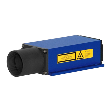
ASTECH VLM500-MID User manual

User Manual
VLM500-MID
Version 1.0

VLM500-MID User Manual
Contents
page 2
ASTECH GmbH
Remarks
The information provided in the manual on hand have been carefully investigated and processed. Still, we cannot
assume any kind of liability regarding completeness or mistakes. However, we are always grateful to get feedback
and proposals.
Claims for damages are, except in the case of premeditation or negligence, in principle excluded.
As a series of versions of this product is available, deviations from the manual on hand might occur, if applicable.
We reserve ourselves the right to implement technical modification that serves to optimize of the product
without related notification. Thus, it cannot be assumed that subsequent product versions show the same
properties as the one on hand.
Registered trademarks are the manufacturer’s property.
VLM500-MID –User Manual V1.0
Copyright © ASTECH Angewandte Sensortechnik GmbH, Rostock 2020
VLM500-Series as of hardware version 2018, Firmware version as of V1.31r0
CDB-Series as of hardware version 2018, Firmware version as of V1.24r1
Date of printing: 10.10.2020
Revision history
Revision
Date
Changes
1.0
10.10.2020
First release
ASTECH GmbH, Schonenfahrerstr. 5, D-18057 Rostock
Internet: www.astech.de E-Mail: info@astech.de
Telephone: +49 (0)381 / 44073-0 Telefax: +49 (0)381 / 44073-20

Contents
VLM500-MID User Manual
ASTECH GmbH
page 3
Table of contents
Table of contents...................................................................................................................................... 3
Commands and parameters of the VLM500-MID....................................................................................... 5
List of figures............................................................................................................................................ 7
List of tables .............................................................................................................................................8
1General information ................................................................................................................................. 9
1.1 Information on how to work with this manual......................................................................................................9
1.2 Safety instructions...............................................................................................................................................9
2Device description .................................................................................................................................. 10
2.1 Intended use ..................................................................................................................................................... 10
2.2 Two components –one device........................................................................................................................... 10
2.3 Measuring principle........................................................................................................................................... 11
2.4 LED-Indicators ...................................................................................................................................................13
2.5 Software integrity and software identification....................................................................................................14
2.6 Preset length outputs ........................................................................................................................................15
3Operating modes.................................................................................................................................... 16
4Device models ........................................................................................................................................ 17
5CDB Handling.......................................................................................................................................... 18
5.1 Keypad..............................................................................................................................................................18
5.2 Switch-on procedure ......................................................................................................................................... 18
5.3 Menu structure .................................................................................................................................................19
5.4 Measurement display ........................................................................................................................................21
5.5 Stored data .......................................................................................................................................................22
5.5.1 Measurement list ......................................................................................................................................22
5.5.2 Storage period and memory size................................................................................................................22
5.5.3 Measurement details.................................................................................................................................22
5.5.4 Searching for specific measurement data................................................................................................... 23
5.5.5 Invalid measured values ............................................................................................................................24
5.6 Device information ............................................................................................................................................24
5.7 Settings.............................................................................................................................................................26
6Performing a measurement process........................................................................................................ 28
7Assembly................................................................................................................................................ 30
7.1 VLM500.............................................................................................................................................................30
7.2 CDB...................................................................................................................................................................32
8Connections and Interfaces..................................................................................................................... 33
8.1 General ............................................................................................................................................................. 33
8.2Power supply and grounding.............................................................................................................................. 34
8.3 Switching in- and outputs ..................................................................................................................................34
8.4 Service interface USB.........................................................................................................................................35
8.5 Printer connection.............................................................................................................................................36
8.6 Protocol output (not legally relevant, optional) .................................................................................................. 36
8.6.1 Serial interface ..........................................................................................................................................38
8.6.2 Profinet IO................................................................................................................................................. 39
8.6.3 EtherNet/IP............................................................................................................................................... 41
8.6.4 Ethernet....................................................................................................................................................41
8.7 Analog output (not legally relevant, optional)..................................................................................................... 42
8.8 Pulse output for encoder emulation (not legally relevant, optional)....................................................................42
8.8.1 Open Collector ..........................................................................................................................................42
8.8.2 Push Pull 5V (IP5V) .................................................................................................................................... 42
8.8.3 Push Pull 24V (IPPP)...................................................................................................................................43

VLM500-MID User Manual
Contents
page 4
ASTECH GmbH
8.9 Process data output (not legally relevant, optional)............................................................................................ 43
8.9.1 Profinet IO................................................................................................................................................. 43
8.9.2 EtherNet/IP............................................................................................................................................... 46
8.9.3 Ethernet....................................................................................................................................................46
9Maintenance .......................................................................................................................................... 47
9.1 General ............................................................................................................................................................. 47
9.2 VLM500 - Window.............................................................................................................................................47
9.3 LED lamp........................................................................................................................................................... 48
10 Service application VLMTool ................................................................................................................... 49
11 Commands and parameters of the VLM500 ............................................................................................ 50
11.1 Notes on use .....................................................................................................................................................50
11.2 Permitted parameter changes in secured mode .................................................................................................50
11.3 Test mode.........................................................................................................................................................50
11.4 Type and device-specific parameters.................................................................................................................. 50
11.5 Commands for system information ....................................................................................................................51
11.6 Legally relevant parameters............................................................................................................................... 52
11.7 Legally relevant commands................................................................................................................................ 65
11.8 Non-legally relevant parameter..........................................................................................................................68
11.8.1 Analog output ........................................................................................................................................... 68
11.8.2 Commands for pulse output 1....................................................................................................................69
11.8.3 Commands for pulse output 2 and 3 .......................................................................................................... 71
11.8.4 Commands for serial interface 2 (Process data output)...............................................................................71
11.9 Non-legally relevant commands.........................................................................................................................72
12 Commands and parameters of the CDB................................................................................................... 75
12.1 Legally relevant commands and parameters....................................................................................................... 75
12.2 Non-legally relevant commands and parameter .................................................................................................76
13 Technical data ........................................................................................................................................ 81
14 Appendix................................................................................................................................................ 82
14.1 Parameter overview VLM500............................................................................................................................. 82
14.2 Parameter overview CDB...................................................................................................................................85
14.3 Error numbers...................................................................................................................................................86
14.4 Terminal assignment.......................................................................................................................................... 90
14.5 Plug connector ..................................................................................................................................................92
14.6 Dimensional and installation drawings ............................................................................................................... 94
15 Declaration of conformity....................................................................................................................... 96

Contents
VLM500-MID User Manual
ASTECH GmbH
page 5
Commands and
parameters of the
VLM500-MID
VLM500
System commands
AO .................................................................... 51
Constant.............................................................. 51
Error.................................................................... 51
Fmax....................................................................51
Info .................................................................... 51
Listerror............................................................... 51
Parameter ........................................................... 51
PO1 .................................................................... 51
PO2 .................................................................... 51
PO3 .................................................................... 51
Post ....................................................................51
Serialnumber.......................................................51
SO1 .................................................................... 51
SO2 .................................................................... 51
Temperature........................................................52
Tmax ................................................................... 52
Tmin.................................................................... 52
Type ....................................................................52
Legally relevant parameter
The command Amax ............................................52
The command Amplifier.......................................52
The command Average ........................................ 53
The command Bw ................................................53
The command Calfactor....................................... 53
The command Calibrate....................................... 54
The command Clock.............................................54
The command Controltime................................... 54
The command Controlhold...................................55
The command Date ............................................. 55
The command Epsilon.......................................... 55
The command Exposure....................................... 55
The command Expmax......................................... 56
The command Expmin.......................................... 56
The command Direction....................................... 56
The command Holdtime....................................... 57
The command Illumination ..................................57
The command Illmax............................................ 57
The command Illmin ............................................ 57
The command Lengthoffset ................................. 58
The command Minrate ........................................58
The command Mode............................................58
The command OED .............................................. 59
The command Permax .........................................59
The command Permin.......................................... 59
The command Rateinterval..................................59
The command Senslevel....................................... 60
The command SO1Format....................................60
The command SO1On .......................................... 62
The command SO1Sync........................................ 62
The command SO1Time ....................................... 62
The command Tracking........................................62
The command Trigger..........................................63
The command Vmax............................................ 64
The command Vmin.............................................64
The command Window ........................................65
Legally relevant commands
Restart................................................................. 66
Restore................................................................ 66
Start .................................................................... 66
Stop ....................................................................66
Store....................................................................66
Update ................................................................ 67
Non-legally relevant parameter
The command AOMax ......................................... 69
The command AOMin .......................................... 69
The command AOOn............................................ 69
The command AOSync ......................................... 69

VLM500-MID User Manual
Contents
page 6
ASTECH GmbH
The command AOValue ....................................... 69
The command PO1Factor..................................... 69
The command PO1Hold ....................................... 70
The command PO1On .......................................... 70
The command PO1Output.................................... 70
The command PO1Sync........................................ 70
The command PO1Value......................................70
The Command SO2Format ...................................71
The Command SO2Interface................................. 71
The command SO2On ..........................................72
The command SO2Sync........................................72
The command SO2Time .......................................72
Non-legally relevant commands
Leave...................................................................72
Savenlp................................................................ 72
Standby ............................................................... 72
TestFilter ............................................................. 73
TestIO.................................................................. 73
TestMeasure........................................................73
TestPS..................................................................73
TestComp ............................................................ 74
Simulation ........................................................... 74
Video...................................................................74
CDB
Legally relevant commands
Command: %date ................................................75
Command: %deletenvm.......................................75
Command: %duration.......................................... 75
Command: %overwrite ........................................75
Command: %time ................................................75
Command: %unit .................................................76
Command: %update ............................................76
Non-legally relevant commands
The Command %additionalunit ............................ 76
The Command %article1 ...................................... 76
The Command %article2 ...................................... 77
The Command %article3 ...................................... 77
The Command %company.................................... 77
The Command %errorlevel................................... 77
The Command %info............................................77
The Command %machine.....................................78
The Command %mode......................................... 78
The Command %parameter ................................. 78
The Command %presetlength1............................78
The Command %presetlength2............................78
The Command %printdoc..................................... 78
The Command %restart ....................................... 79
The Command %readdata....................................79
The Command %SO3Interface.............................. 79
The Command %SO4Interface.............................. 79

Contents
VLM500-MID User Manual
ASTECH GmbH
page 7
List of figures
Figure 1: The VLM500-MID as a part of a length measuring machine............................................................... 10
Figure 2: Simplified structure of a VLM500...................................................................................................... 12
Figure 3: Checksums ....................................................................................................................................... 14
Figure 4: Software identification ..................................................................................................................... 14
Figure 5: CDB with programming adapter........................................................................................................ 16
Figure 6: CDB with sealed programming connector ......................................................................................... 16
Figure 7: CDB with sealed screwed connector ................................................................................................. 16
Figure 8: Main menu of CDB............................................................................................................................ 19
Figure 9: CDB menu structure ......................................................................................................................... 20
Figure 10: Menu "Display Measurement"........................................................................................................ 21
Figure 11: Menu "Stored data"........................................................................................................................ 22
Figure 12: Details of a saved data set .............................................................................................................. 23
Figure 13: Mask to search for a specific date................................................................................................... 23
Figure 14: Mask to search for a specific dataset............................................................................................... 24
Figure 15: CDB Status page ............................................................................................................................. 25
Figure 16: Principle structure of a triggered length measurement.................................................................... 28
Figure 17: Timing diagram of a level-triggered length measurement................................................................ 28
Figure 18: Timing diagram of an edge-triggered length measurement ............................................................. 29
Figure 19: Working distance and alignment towards the measurement object surface .................................... 30
Figure 20: Alignment towards the velocity vector............................................................................................ 30
Figure 21: VLM500 with linear unit LJ2............................................................................................................ 31
Figure 22: VLM500 with mounting plate RMPL1.............................................................................................. 31
Figure 23: CDB with swiveling and tilting device holder ................................................................................... 32
Figure 24: VLM500 device connections............................................................................................................ 33
Figure 25: CDB device connections.................................................................................................................. 33
Figure 26: wiring example for the CDB outputs................................................................................................ 34
Figure 27: wiring example of the CDB inputs ................................................................................................... 35
Figure 28: CDB Profinet sensor page................................................................................................................ 39
Figure 29: VLM500 analog output ................................................................................................................... 42
Figure 30: VLM500 Profinet sensor page ......................................................................................................... 44
Figure 31: Window of the VLM500.................................................................................................................. 47
Figure 32: Exchange of the LED-unit................................................................................................................ 48
Figure 33: Active length measurement or active trigger signal depending on the command Trigger................. 64
Figure 34: Examples for analog output ............................................................................................................ 68
Figure 35: Assembly instruction for shielded plug connectors connections 1, 2, 4 and 5................................... 92
Figure 36: Assembly instruction for shielded plug connectors connection 3, VLM500 ...................................... 92
Figure 37: Assignment of the plug connector (Display on the plug page).......................................................... 93
Figure 38: Dimensional and installation drawings for VLM500 ......................................................................... 94
Figure 39: Dimensional and installation drawings for CDB ............................................................................... 95

VLM500-MID User Manual
Contents
page 8
ASTECH GmbH
List of tables
Table 1: Indicators of the VLM500-MID........................................................................................................... 13
Table 2: VLM500 device models...................................................................................................................... 17
Table 3: Display symbols and there meaning................................................................................................... 18
Table 4: Data output structure ........................................................................................................................ 40
Table 5: Profinet Process data modes.............................................................................................................. 44
Table 6: EtherNet/IP data structure................................................................................................................. 46
Table 7: Replacement windows....................................................................................................................... 47
Table 8: Parameter for command Tracking...................................................................................................... 62
Table 9: Legally relevant VLM500 parameter................................................................................................... 82
Table 10: Non-legally relevant VLM500 parameter.......................................................................................... 84
Table 11: Legally relevant CDB parameter ....................................................................................................... 85
Table 12: Non-legally relevant CDB parameter ................................................................................................ 85
Table 13: Error codes of VLM500..................................................................................................................... 86
Table 14: Error codes of CDB........................................................................................................................... 89
Table 15: Device connection 5, VLM................................................................................................................ 90
Table 16: Device connection 3, VLM................................................................................................................ 90
Table 17: Device connection 3, CDB ................................................................................................................ 90
Table 18: Device connection 4, CDB ................................................................................................................ 91
Table 19: Device connection 5, CDB ................................................................................................................ 91
Table 20: Device connection 6, CDB ................................................................................................................ 91

General information
VLM500-MID User Manual
ASTECH GmbH
page 9
1General information
1.1 Information on how to work with this manual
Commands and functions are displayed in italics. The use of upper case and lower-case letters serves for
improving the readability:
e.g. SO2On (Command for switching on the output at the serial interface S2).
The abbreviated form recommended for the input is additionally displayed in bold letters in the syntax:
e.g. SO1Format (Command for programming the serial interface 1).
The following signs are used:
n Integral number s String
f Floating point number [ ] Optional
c Sign
The following acronyms are used for the measurement parameters:
V Velocity N Object counter
L Length R Measuring rate
1.2 Safety instructions
These safety and operating instructions should be carefully read and followed during practical work with the
device. Compliance with all specified operating conditions is necessary. Failure to observe advisory notes or
nonconforming product usage may cause material damage to the VLM500-MID or lead to wrong measurement
results. Cable connectors must not be plugged or unplugged under voltage. Remember to turn voltage supply off
before you begin working on cable connections.
A light emitting diode (LED) is used as the light source for the VLM500. The LED classification is subject to the
potential photobiological hazard according EN/IEC 62471 named “Photobiological safety of lamps and lamp
systems”. They are not classified according EN 60825 “Safety of laser products”. The lamp of the VLM500 is
classified to the risk group RG-2 (moderate risk) according to the manufacturer. That means that the lamp
represents no hazard due to the natural reaction to look away from bright light sources. The following advice
should be considered anyhow.
Do not stare at operating lamp. It may be harmful to the eye.
Machine directive 2006/42/EC
In the sense of the EU directive “2006/42/EC” the VLM500-MID is not a machine. Hence there is no conformity
declaration available for the device. The directive 2006/42/EC regularizes the requirements on machines. Here,
a machine is meant to be the entity of connected parts or mechanisms (see also EN 292-1, section 3.1). The
VLM500-MID is part of the electrical and sensor equipment of a machine. The machine manufacturer must
consider the VLM500-MID in its process for the declaration of conformity.

VLM500-MID User Manual
Device description
page 10
ASTECH GmbH
2Device description
2.1 Intended use
The measuring device for velocity and length VLM500-MID (the known VLM500 connected with a device to store
and display the measured length values, CDB) is suited for measurements on different materials. The scope of
applications of the VLM in process automation is an extremely wide one. Typical applications are length
measurement of web-type materials and the cutting control or post-control of sheets, profiles and tubes.
The VLM500-MID is designed for the integration into a length measuring machine (LMM). Dependent on the
intended use of the LMM, a calibration of the machine according to the local authorities, can be necessary. In
this sense the VLM500-MID is treated as counter. The counter was pre-tested by the national certification body
„Physikalisch Technische Bundesanstalt (PTB)“ located in the city of Braunschweig, Germany. With the purchase
of the VLM500-MID the customer receives the confirmation, that the device corresponds to the requirements of
the software guide WELMEC 7.2. This guide provides technical guidance for the application of the Measuring
Instruments Directive (MID 2014/32/EU), for software-equipped measuring instruments.
1
This simplifies the
integration and the calibration process for plant manufacturers.
2.2 Two components –one device
General
The VLM500-MID consists of the two main components VLM500 and CDB. The VLM500 is the sensor. The CDB is
a display and storage unit. The length values recorded by the VLM500 are displayed on the CDB screen. When a
length measurement has been completed, the length value is saved together with status information as a data
record in the CDB. If necessary, the data record can also be output via a digital interface. The user can navigate
through a user interface using four buttons located below the display, call up saved measured values and print
them out if necessary. In unsecured mode, the VLM500-MID is parameterized via a serial communication
interface. Both units are connected with a cable.
2
The CDB is supplied with power from the VLM500 via this
connection. Furthermore, the data exchange between themodules takes place via the cable. The housing of both
units is IP 65 rated. The power supply is done with 24 VDC.
Figure 1: The VLM500-MID as a part of a length measuring machine
1
The VLM500-MID fulfills the accuracy class III according to the measuring instrument directive.
2
The customer can select between 5m and 10m cable length.

Device description
VLM500-MID User Manual
ASTECH GmbH
page 11
Interfaces
The VLM500-MID provides different interfaces for the integration into a length measuring machine. There is an
optional dedicated digital protocol interface (RS232, USB, RS422/RS485, ProfiNet, Ethernet/IP, Ethernet) in the
CDB available to share the length measurement protocols. If the protocol needs to be printed out, a serial printer
interface is available by default. The VLM500 can be equipped with an optional analog interface (current
interface 4-20mA) to connect a gauge for visualizing the actual speed or measurement rate. For machine control
up to three pulse outputs and an additional field bus interface (ProfiNet, Ethernet/IP, Ethernet) can be installed
in the VLM500.
CDB unit
The CDB (Control-Display-Box) is a combined display, control and storage unit. It shows the values transmitted
by the VLM500 on the LCD (liquid crystal display). In addition to the length, the current speed and the measuring
rate are also displayed. Further information shown on the screen are the current time and date.
If a triggered length measurement takes place, the final length value is automatically and permanently stored as
a data record in the integrated non-volatile memory together with further information, like length unit, time,
date. In the case of a manual length measurement, the measured value must be confirmed by pressing a key so
that it can be saved automatically.
If the VLM500-MID is equipped with a data interface, this data record is automatically output to the data
interface (not legally relevant). Furthermore, metadata (e.g. batch number, article number) can be transmitted
to the CDB for protocol purposes. These can be changed continuously (e.g. for a changing article number) and
are permanently stored together with the data record in the integrated non-volatile memory. They are not legally
binding. The metadata is also printed on the optional label and transferred to the data interface.
With the help of the buttons located below the display, the user can navigate through a menu structure and call
up saved measured values and other information about the device. Further information on using the CDB can be
found in chapter 5.
Programming
The device is set and parameterized via a USB interface installed in the CDB. Necessary parameter settings or
firmware updates can be made with the parameterization software VLMTool. This comfortable application is
available to the user free of charge and can be installed on several Windows PCs. The individual commands of
the VLM500-MID are described in chapters 12 and 13. The set parameters can be saved permanently in the
device.
2.3 Measuring principle
The VLM500-MID works contact-free optically and implements the physical principle of the spatial filter
3
on the
basis of a charged coupled device sensor (CCD): Optically resolvable structures of the material surface are
displayed on the CCD sensor. This converts the movement directly into a frequency from which the velocity is
calculated. A consecutive internal integration calculates the length. The internal integration can simply be
controlled via an external signal (Start/Stop via the input: Trigger). The calculation of the velocity and the
integration of the length are implemented signed. The direction can be controlled via an external signal. An
automatic direction detection is optionally available.
The function of the VLM500 can be described in a simplified way as follows:
The lens is aligned with the moving object to be measured. The measurement object is mapped onto the CCD
line using a combination of lenses. The optical grating is implemented using a special scanning process for the
CCD line. The CCD line does not record images in the traditional sense. A built-in light source in the form of a
3
Spatial filter is a generic term of a measurement principle for contact-free determination of velocity and
length of moving materials. The spatial filter is based on the filtering effect of grid-shaped structures.

VLM500-MID User Manual
Device description
page 12
ASTECH GmbH
white light LED is used to illuminate the measurement object. Due to the broadband nature of the light, the
greatest possible degree of surface independence is achieved. Any extraneous light that occurs is effectively
suppressed by using a differential measurement method.
When the object moves, the optical grating produces a frequency that is proportional to its speed, i.e. the
structure of the measurement object (contrast differences) generates an analog signal that is sinusoidal. This
signal is called “burst”. After filtering these bursts, the device evaluates them. The signal frequency fSignal is
measured and the speed v is calculated from this with the aid of a proportionality factor k. The proportionality
factor is significantly influenced by the imaging optics and other device-specific parameters. The following
applies:
To adapt the VLM500 to the speed of the measurement object or its reflection behavior, control loops are
implemented in the device that allow automatic adaptation to a wide variety of materials (surface structure and
brightness of the material). Figure 2 shows a simplified internal structure of the VLM500.
Figure 2: Simplified structure of a VLM500
The VLM500 evaluation electronics determine the frequency of the signals (bursts). It realizes a short-term
frequency measurement by evaluating individual periods. The speed is calculated by multiplying the frequency
with the device constant and the calibration factor. The object length can be determined by integrating the speed
over time. The integration can be controlled by an external signal (trigger). Length measurements of greater than
0 m up to a maximum length of 100,000.00 m (in the meter setting) or 500,000.00 km (in the kilometer setting)
are possible. Lengths under 10 m are generally saved as invalid measured values
4
. The current length values are
transmitted to the CDB display at regular intervals and displayed there. A measuring rate "R" is also calculated.
It can be used to optimize device assembly and monitor the measurement function.
4
A minimum length of 10m is required to comply with the MID accuracy class.

Device description
VLM500-MID User Manual
ASTECH GmbH
page 13
2.4 LED-Indicators
The VLM500-MID has integrated LED to display operating states. The VLM500 has five LED in the lid, whereas the
CDB has one LED in the membrane keyboard.
Table 1: Indicators of the VLM500-MID
LED
Color
Meaning
Signal LED
Green
1. Measurement signal available
2. in connection with parameter Minrate: good signal
Red
1. No signal available
2. in connection with parameter Minrate: the threshold value not exceeded
Orange
In connection with parameter VMIN: signal available, but threshold value not
reached
Off
Device off or bad device condition
Busy LED
Yellow
Command processing, also during calibration and simulation
Flashes while device is in standby mode
Off
Device off or no command processing
Error LED
Red
Flashes permanently in case of fatal errors or flashes briefly in case of critical
errors
Off
Device off or no error pending
Forward LED
Green
Direction set to forward or forward automatically detected5
Forward means: object movement from VLM500 bottom to lid
Off
Device off or backward direction set/detected
Automatic direction recognition: off when no direction was detected
Backward LED
Green
Direction set to backward or backward automatically detected
Backward means: object movement from lid to VLM500 bottom
Automatic direction recognition: off when no direction was detected
Off
Device off or forward direction set/detected
CDB LED
Green
CDB ready for operation
Red
Error pending
Orange
Communication with VLM500
off
Device off or bad device condition
Signal LED
A red signal LED may have different reasons:
1. No measuring object available, measuring object outside the working range of the VLM500,
2. Measurement object does not move or is outside the velocity range,
3. Measurement object does not have sufficient structure,
4. Measuring object too bright - Sensor is permanently over exposed,
5. Windows dirty.
The output 'STATUS' is switched parallel to the signal LED. As soon as it lights green, 'STATUS' is switched on.
When the signal LED is yellow, ‘STATUS’ is switched off.
5
For option Automated Direction Recognition only

VLM500-MID User Manual
Device description
page 14
ASTECH GmbH
Error LED
If the red Error LED lights permanently, a technical defect has occurred. If it lights briefly or permanently during
operation, parameters are wrongly set or transfer errors have occurred. In all cases, the reason should be
determined and removed with a PC and the command Error as errors with the measurement results may occur
otherwise.
The Signal LED and the Busy LED lights yellow and the Error LED red during the initialization after switching on
the device or after the command Restart.
2.5 Software integrity and software identification
A key feature of tested software is the compliance with integrity. Integrity exists when software programs run as
intended or unchanged. In order to comply with this requirement, the integrity must be checked regularly. One
technical implementation is the possibility of calculating checksums with the CRC16 algorithm. The checksum is
then compared with a known (reference) value. If the reference value and actual value are identical, it can be
assumed that the integrity is guaranteed and that there has been no intentional or unintentional manipulation
of the software.
Various checksums are calculated in the VLM500-MID. In addition to the two checksums for the software of the
VLM500 and the software of the CDB, a checksum is also calculated from the legally relevant parameters of the
VLM500 and from the legally relevant parameters of the CDB.
The software automatically carries out the integrity check every 60 minutes. If at least one of the checksum
deviates from the reference value, the user is informed of this state with a message and the VLM500-MID is
switched to the unsecured state.
If the user wants to check the software integrity, this can be done via the menu "Device information / Checksum"
(see Figure 3
6
).
Figure 3: Checksums
Figure 4: Software identification
A calibrated length measurement machine has a software that mustn’t be changed. The installed software with
its version number and its release date is therefore notified in the calibration documents. In order to check the
installed version of the VLM500-MID, the software identification is shown during the switch-on procedure. By
calling the menu "Device information / Software identification" the software identification can be looked up at
any time (see Figure 4).
6
The checksums shown are exemplary.

Device description
VLM500-MID User Manual
ASTECH GmbH
page 15
2.6 Preset length outputs
The VLM500-MID has two switching outputs for adjustable preset length. These switch when the currently
measured length value is equal to or greater than a previously programmed target length. These nominal lengths
(preset length) can be set via the user interface of the CDB. Both values are entered in meters. For more
information how to adjust the values via the user interface refer chapter 5.7. Electrical specifications about the
outputs can be read in chapter 8.3.
Preselection 1 specifies the length at which the switching output LENGTH I should switch. This switching output
can be used to indicate that the actual measured value will soon be reached. For example, it can be indicated to
a motor controller that a braking ramp is being driven because the movement process will soon end. Preselection
2 can be used as the actual length. If this value is reached, the switching output LENGTH II is switched through.
In this way, an event can be triggered in a controller that triggers an event that automatically saves the
measurement in the VLM500-MID.
The values of preselection 1 and preselection 2 can also be set and saved as parameters via the service interface.
Reaching a preset length switches the associated output. It is not a trigger event to save a
measurement!

VLM500-MID User Manual
Operating modes
page 16
ASTECH GmbH
3Operating modes
Length measurement machines that are subject to mandatory calibration
7
must be protected against
manipulation. That means intentional or unintentional parameter or other changes shall be impossible.
Precautions have been taken for the VLM500-MID that meet these and other requirements. When a length
measurement machine is calibrated, the VLM500-MID is in secure mode. The secure mode is represented by
attaching seals and lead seals to both the VLM500 housing and the CDB housing (see the photo on the cover
sheet of this user manual as an example). The device itself only recognizes the secure mode by the absence of a
special programming adapter. The VLM500-MID software checks its own integrity at regular intervals using the
calculation of checksums. If a checksum does not match the reference value, the device switches automatically
into unsecured mode. This mode is indicated to the user by a flashing exclamation mark framed in a circle ,
which is shown in the upper area of the display.
If the programming adapter is connected to the CDB housing (see Figure 5), the VLM500-MID is always in
unsecured mode. Legally relevant parameter changes can only be made with a connected programming adapter.
When the length measurement machine is calibrated, the connection flange for the programming adapter is
closed with a screwable cap and then a seal is attached over it (see Figure 6). The cable connection between the
main components VLM500 and CDB is also sealed (see Figure 7). This ensures that any manipulation or
falsification of the software or the measurement data is impossible.
Figure 5: CDB with programming adapter
Figure 6: CDB with sealed programming connector
Figure 7: CDB with sealed screwed connector
If the device is in unsecured mode, length measurements can be carried out at any time. But the data set is
marked as non-legal.
7
For more information about the obligation to calibrate a machine consult national directives and/or laws.

Device models
VLM500-MID User Manual
ASTECH GmbH
page 17
4Device models
Different device models of the VLM500 series are available, which are electrically- and connection-compatible.
Most options (interface cards, assembly accessories etc.) can be used for all models. The differences in
measurement range, working distance and distance variance result from the used optics and the signal
processing of the devices VLM500A, VLM500D and VLM500L. All devices of the VLM500 series are suitable for
highly dynamic processes (minimum update rate of 0.2ms), and have an internal length calculation.
The measuring devices must not be operated out of the velocity range specified in the data sheet,
otherwise no proper functioning can be guaranteed. We kindly ask you to consider the parameter
Mode, as it directly effects on the maximum permissible velocity. The parameter Vmax must be
set according to the actual maximum plant velocity. A reserve of 10 % was already considered in
the device.
VLM500A
The VLM500A is designed as universal device and allows measurements on very different materials. The device
can automatically adapt to reflection, color and structure of the material surface in an extremely wide range.
VLM500D
The VLM500D is specifically designed for application on metallic surfaces and a large distance variance.
VLM500L
The device VLM500L is mainly used for measuring lower velocities.
VLM500E
The device VLM500E is mainly used for measuring medium velocities. It has the largest working distance.
Comparison of VLM models
Table 2: VLM500 device models
VLM500A
VLM500D
VLM500L
VLM500E
Nominal distance and
working range
Extended working range
185 ± 15 mm
185 ± 15 mm
240 ± 15 mm
240 ± 30 mm
185 ± 10 mm
185 ± 15 mm
330 ± 30 mm
330 ± 30 mm
Measuring range
-in extended working range8
- with special filter FB2V
- in extended range and FB2V
0.60 to 2200 m/min
(0.01 to 36 m/s)
1.20 to 3000 m/min
(0.02 to 50 m/s)
0.35 to 280 m/min
(0.006 to 4.6 m/s)
0.75 to 570 m/min
(0.012 to 9.5 m/s)
0,18 to 1200 m/min
(0.003 to 20 m/s)
0.72 to 2400 m/min
(0.012 to 40 m/s)
0.18 to 150 m/min
(0.003 to 2.5 m/s)
0.42 to 330 m/min
(0.007 to 5.5 m/s)
0.12 to 250 m/min
(0.002 to 4.1 m/s)
0.30 to 600 m/min
(0.005 to 10 m/s)
0.08 to 100 m/min
(0.002 to 1.6 m/s)
0.25 to 200 m/min
(0.004 to 3.3 m/s)
0.60 to 2000 m/min
(0.01 to 33 m/s)
1.00 to 2700 m/min
(0.016 to 45 m/s)
0.41 to 270 m/min
(0.007 to 4.5 m/s)
0.82 to 540 m/min
(0.014 to 9.0 m/s)
Measurement uncertainty
DIN 1319 / ISO 3534
±0,025 % for reference distance
(±0,05 % in working distance range and ±0,2 % in extended working range)
Reproducibility
DIN 1319 / ISO 3534
±0,025 %
Material
Nearly all surfaces
Metallic surfaces
Metallic and other
surfaces
Metallic and other
surfaces
Application
Universal
Universal
Low velocity
Universal
8
The extended working mode is activated by changing the parameter MODE to 1.

VLM500-MID User Manual
CDB Handling
page 18
ASTECH GmbH
5CDB Handling
5.1 Keypad
Below the CDB display there are four buttons with a raised embossing. With the help of these buttons, the user
can navigate through the menu structure, select menu items and call up information about the system and the
stored measured values.
The keys are designedas softkeys. This means that depending on the selected menu, the buttons have a different
function. The current meaning of a key is indicated by a small icon at the bottom of the screen above the key.
The following table shows the meaning of the possible symbols.
Table 3: Display symbols and there meaning
One menu level back
One menu entry up
One menu entry down
-Reset counter (in manual working mode)
-Switch display between measured value details and metadata
Print data set
Send data set to protocol interface (PLC, PC etc.)
-Enter selected menu entry
-Store data set (in manual working mode)
5.2 Switch-on procedure
The CDB is supplied with power via the VLM500. The CDB is therefore switched on together with the VLM500.
After switching on, the ASTECH logo is shown on the CDB display. This is followed by the display test, the integrity
check of the software and the display of the software identification. The CDB also checks the internal hardware
components like the memory with the measurement data. If the result of this memory test is negative, i.e. the
memory is not available, a message is shown on the display. The counter is then immediately put into the
unsecured mode.
To evaluate the display test, the user must look at the screen and identify any pixel errors. During the integrity
check of the software, checksums are calculated and compared with reference values. All values are displayed
on the screen. The software detects any differences that occur and immediately switches the VLM500-MID into
unsecured mode.

CDB Handling
VLM500-MID User Manual
ASTECH GmbH
page 19
If this occurs, the device can still be operated and used. However, new measured values are saved as invalid
measured values. The software identification (version numbers of the software) is displayed after the checksums.
After this automatic switch-on test run, the menu measurement display is automatically displayed. A length
measurement process can then be started right away.
To get back to the main menu (Figure 8) the softkey must be pressed.
Figure 8: Main menu of CDB
5.3 Menu structure
Figure 9 shows the entire menu structure of the CDB user interface. With the help of the control buttons ( ,
, and ), the user navigates through the menu items and levels and calls up a function. Figure 8 shows
the menu structure of the CDB user interface.

VLM500-MID User Manual
CDB Handling
page 20
ASTECH GmbH
Figure 9: CDB menu structure
Table of contents
Other ASTECH Measuring Instrument manuals