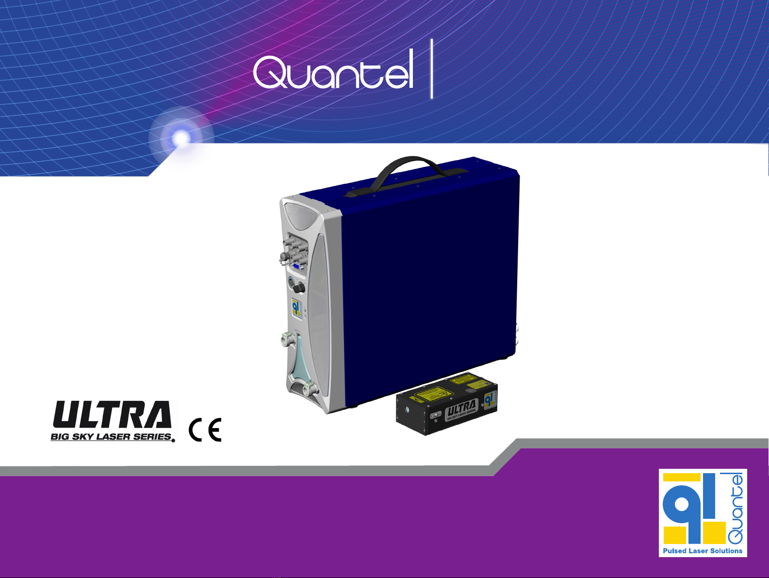
Quantel Ultra Big Sky Laser Series User manual

Tough. Rugged. Reliable. Simply easy to use.
User Manual Ultra
Version M | # DOC00040 April 22, 2012

Tips for Navigating this PDF File
Click on a link to jump to the destination.
Press Alt + to return to the previous location.
Click Contents to return to the Contents page.
Press
Ctrl
+ f to open a search box.
© 2012 Quantel. All rights reserved.
Ultra User Manual
This manual is copyrighted by Quantel and all rights are reserved. This manual may only be reproduced with permission of Quantel. This manual is furnished
for informational use only and is subject to change without notice. This manual does not imply any commitment on the part of Quantel or its business partners.
Quantel and its business partners assume no responsibility or liability for any error or inaccuracies that may appear in this manual.

QUANTEL HEADQUARTERS (Worldwide)
2 bis avenue du Pacifique – Z.A. de Courtaboeuf
BP 23–91941 Les Ulis Cedex – France
Phone: 33-1-6929-1700
Fax : 33-1-6929-1729
QUANTEL USA (North America)
601 Haggerty Lane
Bozeman, MT 59715 USA
Service toll free: 1-800-914-8216
Fax: 1-406-522-2007
www.quantel-laser.com
USER MANUAL
Authorization Memorandum
I have carefully assessed the User Manual for the Ultra.
This document has been completed in accordance with the
requirements of Quantel.
MANAGEMENT CERTIFICATION
Patrick Quero, April 22, 2012
Quality Director & Regulatory Affairs - Quantel Group
User Manual
Document # DOC00040
Version M
April 22, 2012
This manual is provided in digital form to conserve paper.
If you need to print this document, please remember to select
two-sided printing to help keep paper use to a minimum.

Contents
CONTENTS
Laser Safety ................................ 1
1.0 Hazard Information....................... 1
2.0 Terms & Warning Symbols ........... 1
3.0 Acronyms and Abbreviations ....... 1
4.0 General Hazards .......................... 2
5.0 Other Hazards.............................. 3
6.0 Disposal ....................................... 3
7.0 Safe Operation of the Laser ......... 3
8.0 Additional Safety Information ....... 4
Safety Labels.............................. 5
1.0 Laser Head................................... 5
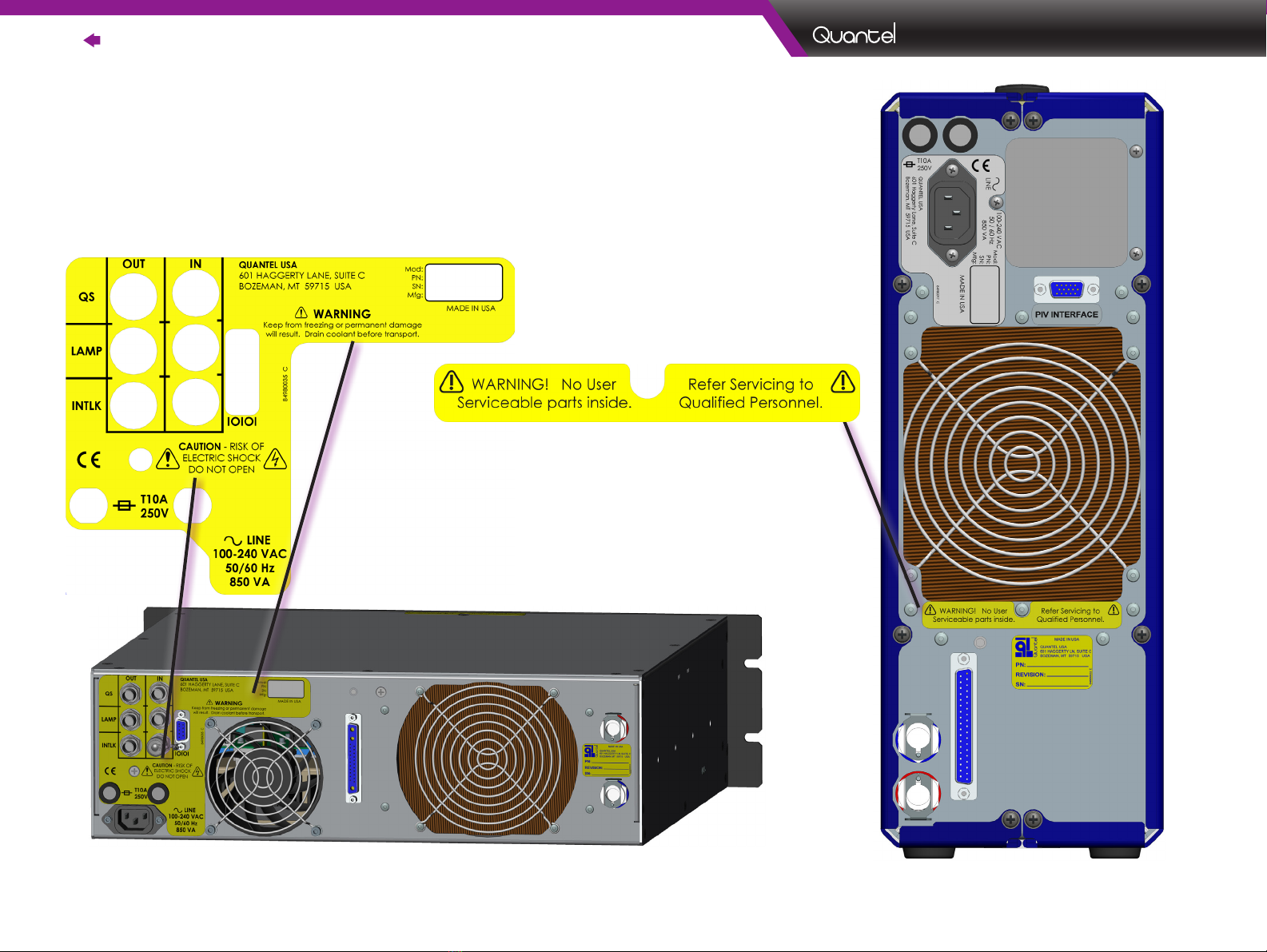
2.0 ICE450 ......................................... 6
3.0 Part/Serial Numbers ..................... 7
Setup ................................................ 8
1.0 Mounting the Laser Head............. 8
2.0 Connecting................................... 9
3.0 Filling the Standard ICE450.......... 11
4.0 Filling the Rack ICE450 ................ 12
Functions....................................... 13
1.0 ICE450 Front Panel Controls ........ 13
2.0 ICE450 Rear Panel ....................... 15
Operation....................................... 16
1.0 Safety ........................................... 16
2.0 Precautions .................................. 16
3.0 Remote Interlock .......................... 16
4.0 Manual Shutter ............................. 17
5.0 Remote Box.................................. 18
6.0 Remote Box Navigation................ 19
7.0 Remote Box Menu,
Detailed Descriptions ................... 20
8.0 Operating Modes ......................... 27
9.0 Manual Modes.............................. 27
10.0 Automatic Mode (INT/INT) ......... 28
11.0 External Modes (EXT) ................ 30
12.0 Example Start-Up Procedure ..... 33
13.0 Shutdown Procedure ................. 33
14.0 Decreasing Output Energy ........ 34
15.0 Increasing Output Energy.......... 34
Software......................................... 35
1.0 Serial Interface ............................. 35
2.0 Serial Command Reference ......... 36
3.0 Quick Reference .......................... 47
Technical Specifications..... 48
1.0 General Specifications ................. 48
2.0 Data Summary Sheet.................... 49
3.0 RS-232 Cable Wiring.................... 50
4.0 External Trigger Signal Req.......... 52
5.0 Timing Diagrams .......................... 53
Optional Equipment................ 56
1.0 Variable Attenuator (MVAT)........... 56
2.0 MVAT Command Set..................... 57
3.0 Hyperterminal Setup for MVAT ..... 58
Drawings........................................ 59
1.0 Cooling System Diagram.............. 59
2.0 Laser Head, 1064nm.................... 60
3.0 Laser Head, 532/355/266 nm
Ultra Stable................................... 61
4.0 Laser Head with GRM, 1064nm ... 62
5.0 Laser Head with GRM
532/355/266nm............................ 63
6.0 Laser Head with Dichroics
532/355/266nm............................ 64
7.0 Laser Head with GRM & Dichroics
532/355/266nm............................ 65
8.0 Laser Head, 1574nm
Ultra Stable.................................. 66
9.0 Laser Head with MVAT
Ultra 1064nm ............................... 67
Maintenance................................ 68
1.0 Scheduled Maintenance .............. 68
2.0 Draining the ICE450 ..................... 68
3.0 Draining a Rack ICE450 ............... 70
4.0 Replacing the DI Cartridge .......... 72
5.0 Transporting the System............... 73
6.0 Replacing the ICE450 Fuses........ 73
7.0 Flashlamp Replacement............... 74
8.0 Nitrogen Purge for the Ultra ......... 76
9.0 Nitrogen Purge for FOLA.............. 77
Troubleshooting ........................ 78
1.0 General Information...................... 78
2.0 Interlocks...................................... 78
3.0 Resolving Interlock Faults ............ 79
4.0 Serial Communications
Troubleshooting ............................ 86
5.0 Diagnosing Problems ................... 87
Warranty......................................... 91
Certificates .................................. 92

Laser Safety | Contents | 1
|
Ultra
Version M 22-April-2012
3.0 Acronyms and Abbreviations
AEL: Accessible Emission Limits
BNC: Bayonet Neill-Concelman RF connector often used with coaxial cable
CFR: Compact Folded Resonator
GRM: Gaussian-Reflectivity Mirror
ICE: Integrated Cooling and Electronics (Laser Power Supply)
I/O: Input/Output
IR: Infrared
LASER: Light Amplification by Stimulated Emission of Radiation
MVAT : Motorized Variable Attenuator
Nd:YAG: Neodymium-doped Yttrium Aluminum Garnet
NLO: Nonlinear Optic
PRF: Pulse Repetition Frequency
PFN: Pulse Forming Network
RB: Remote Box
UHP: Ultra High Purity
1.0 Hazard Information
Hazard information includes terms, symbols and instructions used in this
manual or on the equipment to alert operating and service personnel to the
recommended precautions in the care, use and handling of Class IV laser
equipment.
2.0 Terms & Warning Symbols
DANGER Imminent hazards which, if not avoided, will
result in serious injury or death.
WARNING Potential hazards which, if not avoided, could
result in serious injury or death.
CAUTION Potential hazards which, if not avoided, could
result in minor or moderate injury.
CAUTION Potential hazards which, if not avoided, could
result in product damage.
NOTE
Points of particular interest for more efficient
or convenient equipment operation; additional
information or explanation concerning the
subject under discussion.
WARNING:
LASER
RADIATION
Avoid exposure of eyes or skin to direct
or diffused laser radiation. Permanent eye
damage or blindness may occur.
WARNING:
HIGH
VOLTAGE
Electric shocks and burns from capacitor
discharge or power circuits could lead to
serious injury or even death.
LASER SAFETY
Dimensions listed in this manual are:
U.S. Standard Units inches [SI Metric mm].

2| Contents | Laser Safety
|
Ultra
Version M 22-April-2012
DANGER
Serious
Personal
Injury
This Class IV laser configures to emit 1064nm, 532nm, 355nm, 266nm, 213nm or 1574nm laser radiation.
Do not allow laser radiation to enter the eye by viewing direct or reflected laser energy. Laser radiation may be reflected
from various surfaces; care should be taken to avoid inadvertent reflection of laser energy while working with the laser.
Wear appropriate protective eye-wear when working in an area with an exposed laser beam. Avoid looking directly into
the laser output aperture or at reflections of the beam from other surfaces.
DANGER
Serious
Personal
Injury
This product is not intended for use in explosive, or potentially explosive, atmospheres.
WARNING
Serious
Personal
Injury
U.S. customers should refer to and follow the laser safety precautions described in the American National Standards
Institute (ANSI) Z136.1-2007 document, Safe Use of Lasers. Procedures listed in this Standard include the appointment
of a Laser Safety Officer (LSO), operation of the product in an area of limited access by trained personnel, servicing of
equipment only by trained and authorized personnel, and posting of signs warning of the potential hazards.
European customers should appoint a Laser Safety Officer (LSO) who should refer to and follow the laser safety precautions
described in EN 60825-1,2007 – Safety of Laser Products
WARNING
Serious
Personal
Injury
Materials processing with a laser can generate air contaminants such as vapors, fumes, and/or particles that may be
noxious, toxic, or even fatal. Material Safety Data Sheets (MSDS) for materials being processed should be thoroughly
evaluated and the adequacy of provisions for fume extraction, filtering, and venting should be carefully considered.
Review the following references for further information on exposure criteria:
ANSI Z136.1-2007, Safe Use of Lasers, section 7.3.
U.S. Government’s Code of Federal Regulations: 29 CFR1910, Subpart Z.
Threshold Limit Values (TLVs) published by the American Conference of Governmental Industrial Hygienists (ACGIH).
It may be necessary to consult with local governmental agencies regarding restrictions on the venting of processing vapors.
4.0 General Hazards
The following descriptions are of general hazards and
unsafe practices that may result in product damage, severe
injury or death. Other more specific warnings and cautions
are presented as appropriate throughout this manual.

Laser Safety | Contents | 3
|
Ultra
Version M 22-April-2012
|
Ultra
7. Place warning signs at all work area accesses. The signs must
be appropriate and clearly visible. It is recommended that work
area accesses be interconnected to the Laser Remote Interlock.
8. During normal operation, the laser area (work area) must be
marked off by screens, walls or other means that ensure that
laser beams outside the area are less than the AEL (class 1 type
laser). These screens must not be covered by materials that may
reflect the laser wavelength. They must not be inflammable, nor
may they, when exposed to the direct laser beam (even only for
several seconds), allow laser radiation greater than the AEL limit
to pass.
A warning area limited by barriers is necessary to warn all
people of the potential risk that lies within the laser area.
9. Only qualified people may operate the lasers. When not in use,
the lasers must be completely inoperable. This may be done by
removing the laser key, for example. It must be impossible for
unauthorized people to operate the laser.
10. Aiming laser radiation at individuals, vehicles, aircraft or any
other flying object is prohibited by federal regulations.
11. Due to the risk of electric shock, the power supply must be
switched off and disconnected from the Laser Head prior to any
maintenance operation. Electric shocks or burns resulting from
the power supply may cause serious injury or death.
12. Operate the laser at the lowest possible beam intensity, given
the requirements of the intended application.
13. Increase the beam diameter wherever possible to reduce beam
intensity and thus reduce the hazard.
14. Use an IR detector or energy detector to verify that the laser
beam is off before working in front of the laser.
15. Provide enclosures for the beam path whenever possible.
16. Set up an energy absorber to capture the laser beam, preventing
unnecessary reflections or scattering.
5.0 Other Hazards
The following hazards may be considered typical for this product:
• Risk of exposure to hazardous laser energy and injury through
failure to follow appropriate laser safety procedures.
• Risk of exposure to hazardous laser energy through unauthorized
removal of protective covers.
• Risk of exposure to hazardous or lethal voltages through
unauthorized removal of protective covers.
• Risk of injury when lifting or moving the unit.
6.0 Disposal
This product contains material that is considered hazardous industrial
waste. If for any reason a laser is rendered unusable and is not
repairable, Quantel recommends that disposal of the system follow
all appropriate guidelines for such hazardous waste to prevent
environmental degradation.
7.0 Safe Operation of the Laser
1. Never look at the direct beam from the laser or one of its
reflections. No visual alignment should be made when the
electric power supply of the laser is ON. Permanent eye damage
or blindness may result.
2. Avoid exposing any part of the body to the beam. Avoid blocking
the laser beam with any part of the body.
3. Limit work area access to the required personnel only. Only use
the laser in supervised areas, which are clearly marked and have
supervised access.
4. Remove all objects with a reflecting or shiny surface from the
work area, as well as all inflammable materials.
5. Do not wear reflective jewelry while using the laser, as it may
cause hazardous reflections.
6. Maintain a high level of ambient lighting in the laser operation
area so the eye pupil remains constricted, reducing the
possibility of hazardous exposure.

4| Contents | Laser Safety
|
Ultra
Version M 22-April-2012
8.0 Additional Safety Information
There are several public resources for good laser safety information.
United States
•The American National Standards Institute (ANSI) Z136.1-2007
document Safe Use of Lasers prescribes procedures intended to
promote safety in using lasers. The document describes practices such
as the appointment of a Laser Safety Officer (LSO), operation of the
equipment only by trained personnel and in an area of limited access,
equipment servicing only by trained and authorized personnel, and
appropriate use of warning signs to increase awareness of potential
hazards.
•The Occupational Safety and Health Administration (OSHA) provides an
online Technical Manual (located at www.osha.gov/dts/osta/otm/otm_iii/
otm_iii_6.html). Specifically, Section III, Chapter 6 and Appendix III
contain specific laser safety information.
•The Laser Institute of America (LIA) has a comprehensive web site
(located at www.laserinstitute.org).
Europe
•Norm EN 60825-1 - Safety of laser products, Part 1: Equipment
classification, requirements and user guide
•Norm EN 207 - Personal eye protection - Filters and eye protectors
against laser radiation
•Norm EN 208 - Personal eye protection - Eye protector for adjustment
work on lasers and lasers systems

Safety Labels | Contents | 5
|
Ultra
Version M 22-April-2012
SAFETY LABELS
1.0 Laser Head
The following figures show the safety, model
number, serial number and origination labels,
and their locations on the Ultra Laser System.
These labels are installed at the factory and
should not be removed by the user. If for
some reason a label is removed, obscured or
damaged in any way, please contact Quantel
for a replacement.
LASER HEAD NLO MODULE
MVAT MODULE
OR

6| Contents | Safety Labels
|
Ultra
Version M 22-April-2012
2.0 ICE450
The following images show the safety labels, and their locations
on the Ultra Laser System. These labels are installed at the factory
and should not be removed by the user. If for some reason a label
is removed, obscured or damaged in any way, please contact
Quantel for a replacement.
ICE450 BACK PANEL
19” RACK ICE450 BACK PANEL

Safety Labels | Contents | 7
|
Ultra
Version M 22-April-2012
|
Ultra
3.0 Part/Serial Numbers
The Ultra Laser System has the following labels with
product serial numbers and information:
• System Origination Labels
(located on the ICE450 upright or rack style)
• Part Number Labels
(located on the Laser Head and ICE450
LASER HEAD PART NUMBER LABEL
ICE450 LABEL LOCATION
RACK ICE450 LABEL LOCATION
SYSTEM ORIGINATION LABEL
00XXX00-2
A
1010080105
00XXX00-2
A
1010080109
Have this serial
number ready when
you call customer
service.
Have this serial
number ready when
you call customer
service.

8| Contents | Setup
|
Ultra
Version M 22-April-2012
Figure 1: Bottom View of Laser Head
Note: See details for Setup and Operation of MVAT equipment
under Optional Equipment on page 56.
SETUP
1.0 Mounting the Laser Head
Secure the Laser Head to a flat mounting surface using three (3) 6-32
UNC screws. It is important that the mounting surface be flat, to prevent
distortion of the Laser Head and subsequent misalignment of the
resonator.

Setup | Contents | 9
|
Ultra
Version M 22-April-2012
|
Ultra
LASER
HEAD
ICE450
FRONT PANEL
REMOTE BOX
ICE450
BACK PANEL
2.0 Connecting
Standard Upright Ultra System
CAUTION: Do not power up the laser system
before thoroughly reading the installation and
operation instructions.
1. Verify that the ICE key switch is turned OFF.
2. Connect the I/O cable between the ICE rear panel
and the Laser Head. All connectors are unique and
keyed to ensure proper connection. Secure all non-
locking connectors using the captive fasteners.
CAUTION: These connections carry high
voltage and high current. Ensure that the
connectors are fully inserted and the collars or
screw locks are fully engaged or interlock faults
may result.
3. Remove the blue plastic shipping covers from the
coolant ports. Keep them for reuse.
4. Connect the coolant lines between the back panel
of the ICE and the Laser Head. Connect red to red
and blue to blue. Coolant flows from the ICE into
the Laser Head via the blue hose and returns to the
ICE via the red hose.
5. Verify that the Emergency Stop switch on the
Remote Box is in the OUT position.
6. Connect the Remote Box to the ICE front panel.
7. Connect the AC Mains power cable from the ICE
back panel to 100-240 VAC, 50/60 Hz power.
CAUTION: Ensure the system is connected to
the proper voltage. The voltage rating is marked
on the ICE back panel. Operating the system at
the incorrect voltage may damage the system.
Ensure that the power outlet used is properly
grounded.
TO
100-240 VAC,
50/60 HZ
POWER
I/O CABLE
COOLANT
LINES
EMERGENCY STOP
Figure 2: Connecting a Standard Ultra System

10 | Contents | Setup
|
Ultra
Version M 22-April-2012
Connecting a Rack ICE450
CAUTION: Do not power up the laser
system before thoroughly reading the
installation and operation instructions.
1. Verify that the ICE key switch is turned OFF.
2. Connect the I/O cable between the ICE rear
panel and the Laser Head. All connectors
are unique and keyed to ensure proper
connection. Secure all non-locking connectors
using the captive fasteners.
CAUTION: These connections carry high
voltage and high current. It is necessary to
fully insert the mating connector and fully
engage the collars or screw locks or
interlock faults may result.
3. Remove the blue plastic shipping covers from
the coolant ports. Keep them for reuse.
4. Connect the coolant lines between the back
panel of the ICE and the Laser Head. Connect
red to red and blue to blue. Coolant flows from
the ICE into the Laser Head via the blue hose
and returns to the ICE via the red hose.
5. Verify that the Emergency Stop switch on the
Remote Box is in the OUT position.
6. Connect the Remote Box to the ICE front panel.
7. Connect the AC Mains power cable from the
ICE back panel to 100-240 VAC, 50/60 Hz
power.
CAUTION: Ensure the system is connected
to the proper voltage. The voltage rating is
marked on the ICE back panel. Operating the
system at the incorrect voltage may damage the
system. Ensure that the power outlet used is prop-
erly grounded.
TO
100-240 VAC,
50/60 HZ
POWER
I/O CABLE
COOLANT
LINES
Figure 3: Connecting a Rack ICE450 Ultra System
EMERGENCY STOP

Setup | Contents | 11
|
Ultra
Version M 22-April-2012
|
Ultra
3.0 Filling the Standard ICE450
CAUTION: Do not operate the system until it has been filled. Running
the pump without coolant may damage the pump. Running the pump
without the Laser Head connected may result in pump failure due to
overpressure.
Complete all preliminary steps prior to laser operation, including visual
inspection for damage, filling coolant, properly connecting all cables,
and performing all laser safety precautions.
Always drain the system before shipping or storage. See Draining
the ICE450 on page 68.
Use only distilled water with 1MΩ-cm to 5MΩ-cm resistivity.
1. Connect the fill/drain tube and vent tube to the fill/drain bottle.
Press firmly until you hear the fitting snap into place.
2. Connect the fill/drain tube to the ICE front panel Fill/Drain fitting.
Connect the vent tube to the ICE Vent fitting.
3. Remove the cap and fill the bottle with the approved coolant.
4. Raise the bottle higher than the ICE reservoir. Keep the fill bottle
cap loose.
5. Allow coolant to flow into the ICE reservoir until it rises into the
vent tube.
6. Turn the Key Switch ON (“I”) to power the system.
The pump turns ON automatically when the system is powered ON.
Coolant from the ICE reservoir flows into the coolant lines. When the
coolant falls below the minimum level, the pump automatically turns
OFF and the reservoir-level window lights blink.
7. Using the Remote Box System menu, set the pump to Fill mode.
See Pump on page 26.
8. Refill the bottle. Continue adding coolant until the level is well
above the reservoir-level window minimum mark. When the fluid
level is sufficient, the pump automatically turns ON and again fills
the lines with coolant.
Note: If more than three pump cycles are needed to fill the lines, turn the
power OFF. Wait five seconds, then turn the system ON again.
The reservoir-level light remains ON whenever the coolant is above the
required minimum.
9. Filling is complete when the coolant level is stable and the pump
remains ON.
Figure 4: Filling a Standard ICE450
Vent tube
Fill/drain
bottle
ICE450
Fill tube
Vent
fitting
Fill/Drain fitting
Reservoir-level window
Key
switch
Coolant Loop
(only used when draining)
Fill/Drain
tube
Vent tube
Vent tube
10. Using the Remote Box System menu, set the pump to Normal mode. See
Pump on page 26.
11. Replace the fill/drain bottle reservoir cap.
12. Disconnect the fill/drain bottle from the ICE front panel. The tubing from the
fill/drain bottle may leak. Have a container ready.
13. Purge air bubbles from the Laser Head by tilting it vertically with the
coolant circulating for 10 seconds.
Note: Any time the Laser Head has been disconnected and reconnected, follow this
procedure to purge all of the air from the Laser Head and coolant lines before
operating the laser.
14. Remove the protective sticker from the Laser Head before operating the
system.

12 | Contents | Setup
|
Ultra
Version M 22-April-2012
4.0 Filling the Rack ICE450
CAUTION: Do not operate the system until it has been filled.
Running the pump without coolant may damage the pump.
Running the pump without the Laser Head connected may result
in pump failure due to overpressure.
Complete all preliminary steps prior to laser operation, including
visual inspection for damage, filling coolant, properly connecting
all cables, and performing all laser safety precautions.
Always drain the system before shipping or storage. See
Draining a Rack ICE450 on page 70.
Use only distilled water with 1MΩ-cm to 5MΩ-cm resistivity.
1. Connect the fill/drain tube and vent tube to the fill/drain bottle.
Press firmly until you hear the fitting snap into place.
2. Connect the fill/drain tube to the ICE front panel Fill/Drain
fitting. Connect the vent tube to the ICE Vent fitting.
3. Remove the cap and fill the bottle with the approved coolant.
4. Raise the bottle higher than the ICE reservoir. Keep the fill
bottle cap loose.
5. Allow coolant to flow into the ICE reservoir until it rises into the
vent tube.
6. Turn the Key Switch ON (“I”) to power the system.
The pump turns ON automatically when the system is powered
ON. Coolant from the ICE reservoir flows into the coolant lines.
When the coolant falls below the minimum level, the pump
automatically turns OFF and the reservoir-level window lights
blink.
7. Using the Remote Box System menu, set the pump to Fill
mode. See Pump on page 26.
8. Refill the bottle. Continue adding coolant until the level is well
above the reservoir-level window minimum line. When the fluid
level is sufficient, the pump automatically turns ON and again
fills the lines with coolant.
Note: If it takes more than three pump cycles to fill the lines, turn the
power OFF. Wait five seconds, then turn the system ON again.
The reservoir-level lights remain ON whenever the coolant is above
the required minimum.
9. Filling is complete when the coolant level is stable and the pump
remains ON.
10. Replace the fill/drain bottle reservoir cap and disconnect the fill/drain
bottle from the ICE front panel.
11. Purge air bubbles from the Laser Head by tilting it vertically with the
coolant circulating for 10 seconds.
Note: Any time the Laser Head has been disconnected and reconnected, follow this
procedure to purge all of the air from the Laser Head and coolant lines before
operating the laser.
12. Remove the protective sticker from the Laser Head before operating the
system.
Vent tube
Fill/drain
bottle
RACK ICE450
Fill/drain
tube
Vent
fitting
Fill/Drain fitting
Reservoir-level
window
Connect
vent tube to
upper fitting
Key switch
Figure 5: Filling a Rack ICE450
Coolant Loop
(only used when draining)
Fill/Drain
tube
Vent tube

Functions | Contents | 13
|
Ultra
Version M 22-April-2012
FUNCTIONS
1.0 ICE450 Front Panel Controls
Key Switch
ON: To turn the ICE450 ON, rotate the key to the ON (“I”)
position. With the Key Switch in the ON position, the laser
system is ready for use. The key is not removable when in the
ON position.
OFF: To turn the ICE450 OFF, rotate the key to the OFF (“O”)
position. Remove the key to keep unauthorized personnel from
operating the laser.
Power ON Indicator
This indicator illuminates when the Key Switch is ON and the
unit is connected to 100–240VAC, 50/60 Hz AC Mains power.
The indicator light is amber colored to ensure visibility through
laser safety goggles.
Emission Warning
When high voltage is activated, or when the simmer supply
enables, this indicator illuminates as a warning that laser
output is possible. The indicator light is amber colored to
ensure visibility through laser safety goggles. The user must
observe laser safety precautions when the Emission Warning
indicator is ON.
Remote Box Interface (RB)
Use this input to connect the Remote Box for access to
settings and operating parameters.
Note: The emergency stop button is on the Remote Box. The
Remote Box must be connected to the ICE450 or the laser will
not operate.
Figure 6: ICE450 Front Panel
Key Switch
Power ON indicator
Emission Warning
BNC connectors
Fill/Drain port
Vent port
Reservoir-level
window
Remote Box
connector
Serial interface
(RS-232) port

14 | Contents | Functions
|
Ultra
Version M 22-April-2012
Lamp Out: Use this BNC connector to synchronize with the laser flashlamp
trigger signal. Flashlamp firing corresponds with the rising edge of this
positive signal, which is 5V, 50mA max, and greater than 10µS pulse width.
Q-Switch Out: This BNC connector allows synchronization with the laser
Q-Switch trigger. The Q-Switch trigger corresponds to the rising edge of
this positive signal (5V, 50 mA max, and greater than 10µS pulse width).
Q-Switch In: This is a 50Ω-terminated input. A signal applied to this
BNC connector causes the Q-Switch to trigger if External Q-Switch Trigger
Mode is selected using the Remote Box or the serial interface. The source
of this signal must be capable of supplying a pulse with the following
characteristics (See External Trigger Signal Requirements on
page 52 for details.)
•Amplitude: +5V, acceptable range: {3.0V-5.0V}
•Pulse-width: 100µsec minimum
Computer Serial Port Interface (RS-232): Use this DE-9S D-Sub
connector to operate the system by remote computer control using the
standard RS-232 interface. See Software on page 34 for details on port
configuration and the command set.
Note: To disable remote computer control, press any button on the
Remote Box.
Interlock Out
Interlock In
Lamp Out
Lamp In
Q-Switch Out
Q-Switch In
Computer Serial Port
Interface (RS-232)
BNC Connectors
Interlock Out: Use this BNC output to connect an external laser-
warning indicator. The signal output is low (pulled to ground) when the
laser is disabled. When the laser high voltage is enabled, this connection
outputs +15 VDC and up to 150mA.
CAUTION: This output is not short-circuit protected.
Interlock In: Use this BNC to connect an external safety shutdown
switch. For the laser to operate, this connector must be shorted. When this
circuit is open, the ICE450 high voltage is disabled and discharges in less
than 5 seconds. Install the attached BNC shorting cap on this connector if
this function is unnecessary.
Note: Multiple safety switches must be in a series connection.
Lamp In: This is a 50Ω-terminated input. A signal applied to this BNC
connector causes the flashlamp to fire if External Flashlamp Trigger Mode
is selected using the Remote Box or the serial interface. The source
of this signal must be capable of supplying a pulse with the following
characteristics: (See External Trigger Signal Requirements on
page 52 for details.)
• Amplitude:+5V,acceptablerange:{3.0V-5.0V}
• Pulse-width:100µsecminimum
Figure 7: BNC Connector Locations ICE450

Functions | Contents | 15
|
Ultra
Version M 22-April-2012
|
Ultra
RACK ICE450 REAR PANEL
Fuses for AC
Mains power
Auxiliary I/O
connection
ports
AC Mains power
connector
External I/O
port #1
Serial Interface
port
2.0 ICE450 Rear Panel
AC Mains Power
AC Mains Power Input: Industry standard IEC
60320-power connector for AC Mains power at
100-240 VAC, 50/60 Hz, 850VA.
Fuses: These fuses disconnect the ICE450 from AC
Mains power in the event of an electrical fault. The label
next to the fuse holder lists the specified fuse type and
rating.
CAUTION: Replace the fuses with the specified
fuse only. See Replacing the ICE450 Fuses
on page 73. Failure to do so may result in equipment
damage or personal injury. For your safety, disconnect the
power cord before servicing fuses.
Coolant Ports
Coolant OUT Port: Connect the blue coolant line to
provide coolant to the Laser Head.
Coolant IN Port: Connect the red coolant line to
provide the coolant return from the Laser Head.
Rear Panel Options
See Optional Equipment on page 56 for more details.
Auxiliary I/O Connection Ports: (Available on some
models.) System Interlock, Lamp Sync, Q-Switch Sync,
and RS-232 Port connectors are factory-installed options.
PIV Interface: (Available on some models.) A DA-
15S-HD, D-Sub connector provides fault interlock and
serial communications between the Master and Slave
ICE450 in a dual enclosure PIV system. Contact Quantel
Customer Service for more information.
External I/O Port #1: The CBD25W3F, D-Sub mixed
contact connector provides the interface to the Laser Head.
Fuses for AC
Mains power
AC Mains power
connector
Coolant Out
port
External I/O
port #1
PIV
Interface
Coolant In
port
Figure 8: ICE450 Rear Panel
The ICE450 upright model may
be operated on its side. When
doing so, always orient the Vent
port above the Fill port.
ICE450 on Side
Fill port is down
Vent port is at top

16 | Contents | Operation
|
Ultra
Version M 22-April-2012
3.0 Remote Interlock
This BNC Connector provides an interface for an external safety
shutdown switch. The Remote Interlock can be connected to a lab
door or other system outputs for safety purposes. When using the
Remote Interlock, only an isolated switch, such as a relay, should be
used in order to avoid ground loops. If external safety switches are
used, it is important that they are connected in series.
The Remote Interlock connection must be completed in order to
operate the laser. If an open circuit occurs, the ICE high voltage is
disabled and the Fault indicator is illuminated.
The system is shipped with the BNC shorting cap attached on this
connector. Leave this connector in place if this function is not needed.
OPERATION
1.0 Safety
CAUTION: Obey all safety procedures described in the Safety
section of this manual.
CAUTION: Wear eye protection. Follow safety precautions as
though the system is capable of lasing at anytime.
2.0 Precautions
Follow these guidelines to avoid laser damage.
•Store the laser in a dust-free environment. Keep the Laser Head
covered when not in use. This protects the output window from
dust and particulate.
•The Laser Head is sealed using low-outgassing materials.
Silicone and similar sealing, bonding or insulating materials
should not be used in close proximity to the Laser Head since
these substances will outgas and could contaminate the output
window, causing laser damage.
•Avoid back reflections. Back reflections of even a small
percentage of the output energy can damage optical components
in the Laser Head.
Example: An uncoated convex lens or a glass disk calorimeter
reflects about 4% of the incident energy. While the reflection may
seem harmless, it can perturb the resonator operation and degrade
the near-field beam intensity profile and damage laser optics. It may
also affect the resonator holdoff, causing prelasing and catastrophic
optical damage. In some cases, even anti-reflection coated glass
optics reflect enough energy to damage laser optics. It is best to
use only quality optics coated for the operating wavelength.
CAUTION: To avoid laser damage, minimize back reflections of
the output beam. When reflections are unavoidable, direct
them away from the optical axis of the system by canting the
optics off-axis. Failure to do so can cause laser damage and
void the warranty.
CAUTION: Use of controls or adjustments or
performance of procedures other than those specified
herein may result in hazardous radiation exposure.
This manual suits for next models
1
Table of contents
Other Quantel Measuring Instrument manuals
Popular Measuring Instrument manuals by other brands

Midtronics
Midtronics MDX-652P instruction manual

Tork
Tork AFLOWT BUF-311 Operation manual

ATAGO
ATAGO PAL-Easy ACID4 instruction manual

Bayer HealthCare
Bayer HealthCare RapidPoint 400 Series Service manual

TOA-DKK
TOA-DKK TB-31 instruction manual

RR Mechatronics
RR Mechatronics STARRSED TL Work instructions

Pfeiffer Vacuum
Pfeiffer Vacuum TPR 280 operating instructions

ATP Instrumentation
ATP Instrumentation LX-1309 manual

ekwb
ekwb EK-Quantum Scalar Flow Indicator Bottom-Top... installation manual

Siemens
Siemens SITRANS P Compact operating instructions

PKP
PKP DTL06 instruction manual

Milwaukee
Milwaukee L4 CLL Original instructions