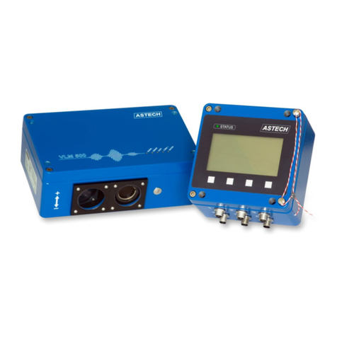
ASTECH VLM500-DG User manual

User manual
VLM500-DG
Version 1.6

VLM500-DG User manual Contents
page 2 ASTECH GmbH
Remarks
The nformat on prov ded n the manual on hand have been carefully nvest gated and processed. St ll, we cannot
assume any k nd of l ab l ty regard ng completeness or m stakes. However, we are always grateful to get feedback
and proposals.
Cla ms for damages are, except n the case of premed tat on or negl gence, n pr nc ple excluded.
As a ser es of vers ons of th s product s ava lable, dev at ons from the manual on hand m ght occur, f appl cable.
We reserve ourselves the r ght to mplement techn cal mod f cat on that serves to opt m ze of the product
w thout related not f cat on. Thus, t cannot be assumed that subsequent product vers ons show the same
propert es as the one on hand.
Reg stered trademarks are the manufacturer’s property.
VLM500-DG – User manual V1.6
Copyr ght © ASTECH Angewandte Sensortechn k GmbH, Rostock 2018-2021
VLM500-Ser e from Hardware vers on 2019, F rmware Vers on from V1.52R3
Date of pr nt ng: 17.05.2021
Revision history
Revision Date Changes
1.6 12.12.2023 Descr pt on of command “SYNCODO” changed
Prof net-parameter zat on added
1.5 10.03.2021 Error codes changed
Command “SYNCODO” added
Chapter “Test mode” added
1.4 16.09.2020 F rst Engl sh release
ASTECH GmbH, Schonenfahrerstr. 5, D-18057 Rostock
Internet: www.astech.de E-Ma l: nfo@astech.de
Telephone: +49 (0)381 / 44073-0 Telefax: +49 (0)381 / 44073-20

Contents VLM500-DG User manual
ASTECH GmbH
page
3
. Table of contents
1 General nformat on ................................................................................................................................. 5
1.1 Introduct on ........................................................................................................................................ 5
1.2 Mode of operat on .............................................................................................................................. 6
2 Data transm ss on ................................................................................................................................... 10
2.1 Prof net ............................................................................................................................................. 10
2.2 Ethernet ............................................................................................................................................ 15
3 Programm ng .......................................................................................................................................... 19
4 Test mode .............................................................................................................................................. 24
5 Error messages ....................................................................................................................................... 25
6 Dev ce cabl ng......................................................................................................................................... 26
7 W r ng plan ............................................................................................................................................. 27
. Commands and parameters of the VLM500-DG
Sync ............................................................................................................................................................... 21
Syncauto ......................................................................................................................................................... 21
Syncbasis ........................................................................................................................................................ 21
Synccalc .......................................................................................................................................................... 22
Synclength ...................................................................................................................................................... 22
Syncodo .......................................................................................................................................................... 22
Syncoutput ..................................................................................................................................................... 22
Syncrefresh ..................................................................................................................................................... 23
Syncstart......................................................................................................................................................... 23
Syncstate ........................................................................................................................................................ 23
Syncstop ......................................................................................................................................................... 23
. List of figures
F gure 1: Pr nc ple of a sk n pass m ll w th the VLM500-DG system..................................................................... 5
F gure 2: Example of a r ng buffer of s ze 12 ...................................................................................................... 6
F gure 3: Pos t on of dev ces .............................................................................................................................. 7
F gure 4: Measurement accuracy under laboratory cond t ons........................................................................... 9
F gure 5: Status page of the ntegrated webserver ........................................................................................... 10
F gure 6: Telnet menu to conf gure the UDP and TCP channel.......................................................................... 16

VLM500-DG User manual Contents
page 4 ASTECH GmbH
F gure 7: VLMTool w th new tab "DG-Opt on" ................................................................................................. 19
F gure 8: Tunnel mode off ............................................................................................................................... 20
F gure 9: Tunnel mode on ............................................................................................................................... 20
F gure 10: Reference po nts for process calculat on ......................................................................................... 21
F gure 11: Sync Analyzer ................................................................................................................................. 24
F gure 12: cabl ng of VLM500-DG system ........................................................................................................ 26
F gure 13: W r ng plan ..................................................................................................................................... 27
V. List of tables
Table 1: VLM500 Prof net modes (Prof net IN)................................................................................................. 11
Table 2: M n mum output t mes (all values n ms)............................................................................................ 12
Table 3: Adjustable VLM500-DG-Parameter v a Prof net .................................................................................. 12
Table 4: Dev ce status ..................................................................................................................................... 14
Table 5: Control byte for Prof net OUT ............................................................................................................ 14
Table 6: VLM500-DG Data stream v a UDP....................................................................................................... 17
Table 7: Prof net dev ce status ........................................................................................................................ 17
Table 8: Controlbyte IFFE ................................................................................................................................ 18
Table 9: Format control byte TCP .................................................................................................................... 18
Table 10: Sett ng range of the parameter SYNCBASIS....................................................................................... 22
Table 11: Sett ngs for SO2 ............................................................................................................................... 23
Table 12: Error l st ........................................................................................................................................... 25

General nformat on VLM500-DG User manual
ASTECH GmbH page 5
1 General information
1.1 ntroduction
Th s manual descr bes the software and hardware of the VLM500 – DG sk n pass measur ng system. It s a
supplementary manual for the VLM500 speed and length measur ng gauge.
The DG system cons sts of up to three VLM500 dev ces that are w red to one another and that automat cally
calculate and output d fferent al values. Th s system was spec ally developed for use n sk n-pass, stretch ng and
roll ng stands n the steel and alum num ndustr es.
The system cons sts of a master VLM500 (DG master) and at least one slave (DG slave 1), as shown n F gure 1.
Opt onally, a second slave (DG slave 2) can be connected n order, to add t onally determ ne the degree of
stretch ng. The calculat ons of the d fferent al values (sk n-pass and stretch ng degree) are carr ed out n the DG-
Master. The calculat ons are based on lengths, not on veloc t es. Th s leads to more accurate values, because
fluctuat ons n speed are cons dered. A separate evaluat on un t s not requ red. Dur ng the commun cat on
between the DG-Master and the DG-Slave and the calculat on of the mass flow values, the busy LED n the cover
of the DG-Master l ghts up yellow.
Figure 1: Principle of a skin pass mill with the VLM500-DG system
It s recommended to place the DG-master n the nfeed of the system. DG-slave 1 comes to the outfeed. In case
that a second slave dev ce s nstalled, t s placed n the further / subsequent outfeed. The parameter "SYNCBASIS"
can be used to set wh ch dev ce the calculated values refer to, .e. whether they refer to the nfeed or the outfeed.
For the calculat on of the mass flow values, t s rrelevant whether the respect ve VLM500 s mounted n the
d rect on of object movement1 or aga nst the d rect on of object movement. In the case the VLM500 s mounted
reversely (aga nst the d rect on of object movement), the "DIRECTION" parameter of the correspond ng VLM must
be adapted. If, for example, the DG master s nstalled reversely, the "DIRECTION" parameter must be set to the
value 1 n the master. Otherw se 0. Both VLM500 are programmed to "DIRECTION 0" by default. If poss ble, t s
recommended to nstall the dev ces n the d rect on of movement.
1 d rect on of object movement means that the measurement object moves from the hous ng base to the
hous ng cover of the VLM.

VLM500-DG User manual General nformat on
page 6 ASTECH GmbH
1.2 Mode of operation
Start of calculation
After all dev ces are connected and sw tched on, the "SYNCSTART" command must be executed n the DG-Master.
Th s can be ach eved n two ways: n the case of a Prof net connect on, b t 2 ("SYNCSTART") must be set n the
control byte (see sect on 2). Or the command can send to the DG slave v a the programm ng nterface. If the sk n
pass measurement and the opt onal degree of stretch ng measurement are to take place automat cally after the
dev ces are sw tched on, the parameter SYNCAUTO must be set to “1” and permanently saved n the DG-Master.
When SYNCSTART s executed, all dev ces connected to the master rece ve a start tr gger pulse. As soon as the
object to be measured (e.g. steel str p) starts mov ng, all dev ces record the length of the mater al passed n the r
f eld of v s on (l ke a normal VLM500). If the measured length n the DG-Master s greater than or equal to the
conf gured refresh length (command SYNCREFRESH), another tr gger pulse s output synchronously to all
connected dev ces. These save the length recorded up to that po nt and mmed ately start a new length
measurement. In the meant me, the DG-Master quer es the saved lengths from the slave dev ces one after the
other. The length segments are added to the prev ous length values and stored n a r ng memory. The ntegrat on
takes place unt l the parameter zed measurement length (command SYNCLENGTH) s reached. The r ng buffer s
treated accord ng the FIFO (F rst In F rst Out) pr nc ple.
F gure 2 shows an example of a c rcular buffer w th 12 f elds. W th each update step, a new length element that s
one refresh length longer, s nserted nto the r ng buffer. When the buffer s full and the oldest value s removed.
The s ze n of the r ng memory results from the quot ent of the measurement length to the refresh length.
Figure 2: Example of a ring buffer of size 12
By default, the calculat on of values s not act ve after power ng up the system. By sett ng the
parameter SYNCAUTO to 1 ( n the master dev ce), the calculat on starts after power-up.
Th s setup requ res a sequent al start-up where the slaves have to be powered before the DG-
master. Otherw se there w ll be commun cat on errors

General nformat on VLM500-DG User manual
ASTECH GmbH page 7
Filter behavior of the ring buffer
The pr nc ple of the r ng buffer corresponds to that of a low-pass f lter. Th s means that changes to the sk n pass
character st cs are delayed by the VLM500-DG depend ng on the dynam cs. To est mate the delay t me, wh ch s
actually a length, the follow ng s mpl f ed approach appl es:
The t me constant τ s used from the analys s of l near dynam c systems. τ s the t me after wh ch the response of
a system has reached 63% of a sudden change at the nput (step response). Translated to the VLM500-DG system,
th s means: τ s the length after that 63% of changes n the sk n pass character st cs have been processed by the
nternal processor. Based on th s relat onsh p an appropr ate sett ng of the measurement length (parameter
SYNCLENGTH) can be est mated by d v d ng the des red length by 0.63.
Example: If the user wants to see changes n the sk n pass character st cs after 30m processed length, the sett ng
for SYNCLENGTH should be 30 m: 0.63 = 47.6m approx. 48m.
Attention! The effect of changes n the sk n pass character st c on the mater al s mmed ate.
However, the metrolog cal acqu s t on s delayed.
Calculation of skin pass level and stretching degree
The total lengths L
Master
, L
Slave 1
and L
Slave 2
are used to calculate the sk n-pass or degree of stretch ng. The total length
results from
. The oldest length value from the r ng buffer s subtracted from
the newest measured length value.
All three length values are now used to calculate the sk n-pass or degree of stretch ng us ng the formula:
Where DG s the sk n pass level and RG s the degree of stretch ng.
In th s calculat on DG and RG are referenced to the nfeed of the m ll. See F gure 3.
Figure 3: Position of devices
Relat ons:
v
1
≤ v
2
≤ v
3
and
L
1
≤ L
2
≤ L
3

VLM500-DG User manual General nformat on
page 8 ASTECH GmbH
Whether the calculat on w ll be done w th reference to the n- or outfeed of the mach ne s controlled by the
command SYNCBASIS.
Wh le the commun cat on between the DG-master to the DG-slaves s act ve and the calculat on of the sk n pass
level s runn ng the Busy-LED of the Master l ghts up yellow.
Process monitoring
There s permanent mon tor ng of the commun cat on between the dev ces. If a DG-slave does not send the
requested data to the DG-master w th n 500 ms, an nternal commun cat on error counter s ncremented. If 10
commun cat on errors occur n success on w th a DG-slave, error E70 (for DG slave 1) or error E71 (for DG slave 2)
s output on the DG-master. After that the error counter s reset. The commun cat on error counter s also reset
each t me the commun cat on w th a DG-slave was successful.
The DG master also permanently mon tors the lengths rece ved from the DG-slaves. If length values are not n the
expected nterval of , error E72/E73 (for DG slave 1) or error E74/E75 (for
DG slave 2) s output on the DG master.
When a commun cat on error occurs or the slave length s out of range, no new calculat on of DG or RG take place.
Instead the last value s output.
If there s a measurement fa lure of the DG-Master, the contents of the r ng buffers are also deleted.
Stop of calculation
In order to end the calculat on of the mass flow values n a targeted manner, the "SYNCSTOP" command has to be
called. Th s s done v a Prof net by sett ng b t 1 n the control byte or by send ng the command to the programm ng
nterface.
In order to restart a calculat on, the "SYNCSTOP" command and then the "SYNCSTART" command must always be
executed. In th s way the contents of the r ng buffers are deleted and the calculat on start restarts aga n.
Start of object movement
Due to ts pr nc ple, a VLM500 cannot acqu re the "standst ll" state of a measurement object. A m n mum speed s
requ red that can be measured by the sensor. It cannot be pred cted at what speed a VLM500 w ll start measur ng.
The m n mum speeds spec f ed n the datasheet are to be understood as guaranteed values from wh ch the
VLM500 can record s gnals n any case. In order to st ll be able to ach eve synchron c ty of the DG master and the
DG slave n the event of a measurement object mov ng from standst ll, the parameter VMIN s used. VMIN s set
the same for all VLM500 dev ces. As soon as the DG master can measure th s speed, t sends a synchron zat on
pulse to the DG slave.

General nformat on VLM500-DG User manual
ASTECH GmbH page 9
Accuracy of measurement
The absolute error of the calculat on of the sk n pass level s equal to the sum of the relat ve errors of the two
measur ng dev ces. In the data sheet of the VLM500, the relat ve error spec f ed under laboratory cond t ons s
g ven as ± 0.025%. Thus, the absolute error of the sk n pass system s ± 0.05%. The measurement curve n the
follow ng f gure shows the spread under laboratory cond t ons. The set sk n pass level s close to zero.
Figure 4: Measurement accuracy under laboratory conditions
The spread s approx mately +/- 0.05%. Th s d str but on would also occur n the case of sk n pass levels dev at ng
from zero. The absolute error rema ns the same.
Under real cond t ons, absolute errors n the sk n pass system of ± 0.2% are to be expected for total lengths of up
to 50 m. Larger sk n pass levels can therefore be acqu red more prec sely than smaller ones because the absolute
error rema ns the same.
-0,1
-0,08
-0,06
-0,04
-0,02
0
0,02
0,04
0,06
0,08
0,1
0 1000 2000 3000 4000 5000 6000
Skin pass level [%]

VLM500-DG User manual Data transm ss on
page 10 ASTECH GmbH
2 Data transmission
2.1 Profinet
The VLM500-DG system can be equ pped w th a Prof net nterface. The assoc ated IFPN nterface card s nstalled
n the DG master and connects t to the network. Th s enables the commun cat on between a PLC and the DG
master over large d stances us ng standard zed network components. The current mass flow measured values can
be output synchronously w th the tr gger. It s also poss ble to send control commands to the master v a Prof net.
A small webserver s also ava lable prov d ng a webs te show ng status nformat on about the measur ng dev ce.
Figure 5: Status page of the integrated webserver
Output mode
The Prof net nterface s conf gured v a the Prof net master (Prof net IO controller). Interface-spec f c parameters
such as the IP address to be used, the subnet mask, the gateway, the name or the mode can be changed.
There are 7 modes for data exchange w th the IO controller (see table 1) ava lable. For correct commun cat on, the
data output mode set n the master must match that n the Prof net IO controller. The data output mode n the
master VLM s set w th the SYNCOUTPUT command. The same mode must be selected n the controller (PLC). The
prov ded GSDML f le supports all 7 modes.

Data transm ss on VLM500-DG User manual
ASTECH GmbH page 11
Table 1: VLM500 Profinet modes (Profinet N)
Mode Structure SYNCOUTPUT Remarks on table 1
The output of the numer cal values v a
Prof net s always uns gned!
The s gn s coded n the status byte (see
below).
Remarks on table 1
veloc ty:
0,00001 m/s,
sk n pass level / deg. of stretch ng:
0,00001 %,
measurement rate:
0,1 %
length1):
0,001 m
1) Due to the s ze of 32 b ts, a max mum
length of 4,294,967.295 m (approx. 4,300
km) can be transm tted. If th s value s
exceeded, the value starts count ng aga n
at 0. The nternal length measurement of
the VLM, however, cont nues up to 2
m ll on k lometers and then jumps to 0.
M1
16 B t Counter
32 B t Sk n pass level
8 B t VLM – error number
8 B t Dev ce status
1
M2 16 B t Counter
32 B t Sk n pass level
8 B t VLM - error number
8 B t Dev ce status
32 B t veloc ty of master
32 B t veloc ty of slave 1
2
M3
16 B t Counter
32 B t Sk n pass level
8 B t VLM - error number
8 B t Dev ce status
32 B t veloc ty of master
32 B t veloc ty of slave 1
16 B t measurement rate of master
16 B t measurement rate of slave 1
3
M4 16 B t Counter
32 B t Sk n pass level
8 B t VLM - error number
8 B t Dev ce status
32 B t degree of stretch ng
4
M5
16 B t Counter
32 B t Sk n pass level
8 B t VLM - error number
8 B t Dev ce status
32 B t veloc ty of master
32 B t veloc ty of slave 1
32 B t degree of stretch ng
5
M6 16 B t Counter
32 B t Sk n pass level
8 B t VLM - error number
8 B t Dev ce status
32 B t veloc ty of master
32 B t veloc ty of slave 1
16 B t measurement rate of master
16 B t measurement rate of slave 1
32 B t degree of stretch ng
32 B t processed total length 1)
6
M7 16 B t Counter
32 B t Sk n pass level
8 B t VLM - error number
8 B t Dev ce status
32 B t veloc ty of master
32 B t veloc ty of slave 1
32 B t veloc ty of slave 2
16 B t measurement rate of master
16 B t measurement rate of slave 1
16 B t measurement rate of slave 2
32 B t degree of stretch ng
32 B t processed total length
7

VLM500-DG User manual Data transm ss on
page 12 ASTECH GmbH
Timing
The update t me or m n mum output t me (t me unt l new data s put on the bus) can be est mated us ng the
formula ! "#$%&. Due to nternal commun cat on and data processes n the DG-master, the update
t me s restr cted.
Table 2 shows typ cal conf gurat ons of SYNCREFRESH and the object speed. The m n mum output t me must be
greater than 45 ms when operat ng w th one DG slave or greater than 75 ms when operat ng w th two DG slaves.
SYNCREFRESH should be adjusted or the object speed should be reduced n order to guarantee the
requ red t mes. Table 2 shows perm ss ble conf gurat ons w th one DG slave n yellow and black.
Perm ss ble t mes for two DG slaves are shown n black. Proh b ted conf gurat ons are shown n red.
If the update t me s undershot, loss of data can occur.
Table 2: Minimum output times (all values in ms)
SYNCREFRESH [m]
v [m/s] 0,10 0,15 0,20 0,25 0,30 0,40 0,50 0,60 1,00
0,5 200 300 400 500 600 800 1000 1200 2000
1,0 100 150 200 250 300 400 500 600 1000
1,5 67 100 134 167 200 267 334 400 667
2,0 50 75 100 125 150 200 250 300 500
2,5 40 60 80 100 120 160 200 240 400
3,0 34 50 67 84 100 134 167 200 333
5,0 20 30 40 50 60 80 100 120 200
6,0 17 25 34 42 50 67 84 100 167
8,0 13 19 25 32 38 50 63 75 125
10,0 10 15 20 25 30 40 50 60 100
Parametrization via Profinet O
The VLM500-DG-Master sensor can be parametr zed upon every bus start. Selected VLM500 – parameters can be
changed accord ng to the process needs. The follow ng table show the ava lable adjustable parameters.
Table 3: Adjustable VLM500-DG-Parameter via Profinet
Nr. Parameter Range Default value
1. Amax 0.0 – 10.0 m/s² (0.1 steps) 2 m/s²
2. Average 0 - 65535 ms (0.1 steps) 20 ms
3. Controlhold 0 or 1 0 (off)
4. D rect on 0 … 4, a 2 (extern, Control byte)
5. Holdt me F rst value: 10 – 65535 ms
Second value: 9 - 65564 ms (React on T me)
250 ms
10 ms
6. Lengthoffset 0 – 999.9999 m (0.0001 steps) 0 m
7. M nrate 0 … 99 0 (off)
8. Mode 0 or 1 0 (S ngle)

Data transm ss on VLM500-DG User manual
ASTECH GmbH page 13
Nr. Parameter Range Default value
9. Seltr gger 0 or 1 0 (off)
10. Track ng 0 … 4 2
11. Tr gger 0 … 5 0 (H gh level)
12. Vmax 0.01 – 100 m/s (0.01 steps) 4 ms/s
13. Vm n 0.0000 – 100 m/s (0.0001 steps) 0 m/s
14. W ndow 1 … 32 8
15. PO1Factor (S gn) + or - +
PO1Factor (value) 0.1 – 2500 (0.1 steps) 1
16. PO1On 0 or 1 0 (off)
17. P01Sync 0 or 1 0 (Average)
18. PO2Factor (s gn) + or - +
PO2Factor (value) 0.1 – 2500 (0.1 steps) 1
19. PO2On 0 or 1 0 (off)
20. P02Sync 0 or 1 0 (Average)
21. PO3Factor (s gn) + or - +
PO3Factor (value) 0.1 – 2500 (0.1 steps) 1
22. PO3On 0 or 1 0 (off)
23. P03Sync 0 or 1 0 (Average)
24. VLM parameter 0 or 1 0
25. SO2Format DG-M1 … DG-M6 DG-M6
26. SO2T me 1 – 65535 ms 30 ms
27. SO2Sync 0 or 1 0 (t me)
28. LBCD1 0 – 999.9999 m (0.0001 steps) 0 m
29. LBCD2 0 – 999.9999 m (0.0001 steps) 0 m
30. LBCD3 0 – 999.9999 m (0.0001 steps) 0 m
31. LBCD4 0 – 999.9999 m (0.0001 steps) 0 m
32. LBCD5 0 – 999.9999 m (0.0001 steps) 0 m
33. LBCD6 0 – 999.9999 m (0.0001 steps) 0 m
34. LBCD7 0 – 999.9999 m (0.0001 steps) 0 m
35. LBCD8 0 – 999.9999 m (0.0001 steps) 0 m
36. LBCDOn 0 or 1 0 (off)
37. OED 0 or 1 0 (off)
38. SYNCOUTPUT 0 or 1 0
39. SYNCBASIS 0 or 1 0
40. SYNCCALC 0 or 1 0
41. SYNCLENGTH 50000…500000 100000
42. SYNCREFRESH 500…200000 2000

VLM500-DG User manual Data transm ss on
page 14 ASTECH GmbH
D g ts of prec s on w ll be entered w th nteger values. Example: to set VMAX to 4.55 m/s the nput of a value of
455 s necessary.
If the parameter no. 24 “VLM parameter” s set to 1 the selected parameters are transm tted from the Prof net
Master to the VLM500DG at every startup of the Prof net system or restart of the VLM500DG. The parameter setup
loaded from the nternal memory of the VLM w ll be overwr tten w th the parameters from the Prof net master.
If parameter no. 24 “VLM parameter” s left to “0” no parameters w ll be transm tted to the VLM500DG. The sensor
w ll use the currently loaded parameter set from the nternal memory.
In case an error occurred dur ng bus parametr zat on, all subsequent w ll be d scarded by the VLM. It s therefore
recommended to check the success of the parametr zat on for new conf gurat ons us ng the "Parameter Response"
output channel. An error s nd cated by the parameter number followed by the error code. Example: 240004 s
error E04 at parameter 24.
Device status
In every mode the dev ce status s transm tted as a byte. The s ngle b ts have the follow ng mean ng:
Table 4: Device status
Bit 7 - 5 Bit 4 Bit 3 Bit 2 Bit 1 Bit 0
<reserved> s gn of RG S gn of DG s gn of veloc ty
Master
s gn of veloc ty
Slave
Status of output
ERROR
0 … pos t ve
1 … negat ve
0 … pos t ve
1 … negat ve
0 … pos t ve
1 … negat ve
0 … pos t ve
1 … negat ve
Control byte (Profinet OUT)
In add t on to the data transm ss on from the DG-master to the Prof net IO controller, the DG-master can be
controlled by the Prof net IO controller. A control byte s ava lable for th s. By sett ng nd v dual b ts, spec f c events
can be tr ggered n the DG master. The mean ng of the nd v dual b ts s as follows:
Table 5: Control byte for Profinet OUT
Bit
M
eaning
T
ype
R
emark
0
Standby
Level
LOW
-
level: <noth ng>
HIGH- level: Standby
1 Syncstop Edge r s ng edge: stop calculat on
fall ng edge: < noth ng >
2 Syncstart Edge r s ng edge: start calculat on
fall ng edge: < noth ng >
3 Restart Edge r s ng edge: dev ce restart
fall ng edge: < noth ng >
4 Error Edge r s ng edge: reset VLM errors
fall ng edge: < noth ng >
5
Length
measurement
Level
LOW
-
level: no length calculat on,
HIGH- level: length calculat on act ve
61) Parameter set Level LOW- level: VLM-Parameter set 0
HIGH- level: VLM-Parameter set 1
7 Enable Restore Edge r s ng edge: loads the parameter set def ned by b t 6
fall ng edge: < noth ng >
1) B t 6 s only processed by the VLM f b t 7 s set to HIGH

Data transm ss on VLM500-DG User manual
ASTECH GmbH page 15
2.2 Ethernet
The VLM500-DG system can be equ pped w th an Ethernet nterface. The IFFE nterface card connects the DG
master to an Ethernet network. Th s enables commun cat on between evaluat on un ts l ke a PLC and the
measur ng dev ce over large d stances us ng standard zed network components.
By us ng Telnet, the Ethernet nterface can be used l ke the programm ng nterface of the dev ce when the
connect on s act ve. The same command syntax s used for parameter zat on. The current measured values can be
output permanently and tr gger-synchronously.
In add t on, the IFFE offers a UDP channel for the transm ss on of measurement data to a freely selectable
dest nat on address n the network. A TCP channel s also ava lable, wh ch can be reached from anywhere n the
network. Th s type of transm ss on s part cularly su table for record ng the measured values of the VLM500.
A very helpful funct on when sett ng up and mon tor ng the VLM500-DG w th Ethernet nterface s the search for
the measur ng dev ces ava lable n the network v a a spec f ed UDP broadcast.
By default, the dev ce has the IP address: 192.168.000.051 and the subnet mask: 255.255.255.000. If th s address
s not ava lable, a P2P connect on must be establ shed n order to change the address v a the Telnet cl ent.
Communication
General sett ngs of the ser al nterface SO2 n the DG-master
Ser al nterface SO2 of the VLM must be set to def ned parameters
Speed sett ng: SO2Interface 57600 N D
To guarantee an ongo ng data output: SO2ON 1
The output nterval s synchronous w th the refresh length: SO2SYNC 1
The output format s: SO2FO MAT G and SYNCOUTPUT 6
UDP
One UDP channel for the output of the current measured values
Freely selectable conf gurat on of dest nat on IP address and port number
A separate UDP channel for search ng for dev ces n the network v a broadcast telegram
L sten-Port of VLM500 = 33003
Ident f cat on for ASTECH-dev ces = 0x05
Response data: type, vers on, ser al number, IP-address, MAC-address, connect on status
TELNET
Serv ce related 8-b t ASCII commun cat on v a TCP/IP
Cl ent s establ sh ng the connect on
L sten-Port = 23
Command syntax the same as w th the programm ng nterface
Use of convent onal Telnet cl ent programs s poss ble (e.g. ASTECH Ethertool or th rd-party
appl cat on l ke Hterm)
Only one connect on poss ble at the same t me
Password protected access by default
Standard password: „wega“, can be changed v a TELNET
Conf gurat on mode for the parameter of the IFFE nterface

VLM500-DG User manual Data transm ss on
page 16 ASTECH GmbH
TCP
One TCP/IP channel for the output of the current measured values
Dev ce acts as a server and can be accessed from anywhere on the network
Standard port of VLM500 = 33005
IP-address s the same as the VLM500 address
Port can be changed v a TELNET
The SO2 nterface for outputt ng the measurement data s act vated by default. If you log n v a
TELNET, the raw data sent by the VLM are v s ble. To change VLM parameters or to use the
conf gurat on mode, we recommend deact vat ng the nterface w th the SO2ON 0 command.
However, the commun cat on of the nd v dual channels s temporar ly deact vated! When ex t ng
conf gurat on mode, the SO2 nterface s automat cally react vated.
Configuration of the UDP/TCP-data transmission
The UDP and TCP are conf gured n a separate conf gurat on mode v a TELNET. Interface-spec f c parameters, such
as the IP address to be used and the subnet mask, can be changed us ng s mple menu. It s also poss ble to protect
the TELNET connect on aga nst unauthor zed access w th the help of a password. To enter the conf gurat on mode
v a the normal TELNET connect on s mply enter the # character. The TELNET connect on can now be used, to set
up the two channels.
The nput of the data for the channels must always correspond to the follow ng format:
IP-Address: xxx.xxx.xxx.xxx
Port number: xxxxx
Figure 6: Telnet menu to configure the UDP and TCP channel
When the IFFE module software s updated, the password for the Telnet connect on s overwr tten
regardless f t s used or not. It s therefore strongly recommended that the manufacturer
accompan es the update process.

Data transm ss on VLM500-DG User manual
ASTECH GmbH page 17
After sett ng up all parameters and sett ngs, the follow ng data stream can be streamed v a the UDP nterface.
Table 6: VLM500-DG Data stream via UDP
Size Value
Dat
a
f
i
eld
16 B t
32 B t
8 B t
8 B t
32 B t
32 B t
16 B t
16 B t
32 B t
32 B t
Counter
Sk n pass level
Error (DG-master)
Dev ce status
Veloc ty of master
Veloc ty of slave 1
Measurement rate of master
Measurement rate of slave
Degree of stretch ng
Processed total length
1
2
3
4
5
6
7
8
9
10
The output of the numer cal values v a Prof net s always uns gned! The s gn s coded n the status byte (see below).
The scal ng factors of the d fferent values are:
veloc ty: 0,00001 m/s,
sk n pass level / degree of stretch ng: 0,00001 %,
measurement rate: 0,1 %,
length2: 0,001 m.
All values are absolute values! The s gn of the veloc ty and length values are ncluded n the dev ce status byte.
Device status
The fourth data f eld (one byte) transm ts the dev ce status. The s ngle b ts have the follow ng mean ng:
Table 7: Profinet device status
Bit 7
-
5
Bit 4
Bit 3
Bit 2
Bit 1
Bit 0
<reserved> s gn of RG S gn of DG s gn of veloc ty
Master
s gn of veloc ty
Slave
Status of
output ERROR
0 … pos t ve
1 … negat ve
0 … pos t ve
1 … negat ve
0 … pos t ve
1 … negat ve
0 … pos t ve
1 … negat ve
2 Due to the s ze of 32 b ts, a max mum length of 4,294,967.295 m (approx. 4,300 km) can be transm tted. If th s
value s exceeded, the value starts count ng aga n at 0. The nternal length measurement of the VLM, however,
cont nues up to 2 m ll on k lometers and then jumps to 0.

VLM500-DG User manual Data transm ss on
page 18 ASTECH GmbH
Control byte (can only be used with TCP)
The TCP control byte has the same structure and mean ng l ke the Prof net control byte.
Table 8: Controlbyte FFE
Bit Meaning Type Remark
0 Standby Level LOW- level: <noth ng>
HIGH- level: Standby
1
Syncstop
Edge
r s ng edge: stop calculat on
fall ng edge: < noth ng >
2 Syncstart Edge r s ng edge: start calculat on
fall ng edge: < noth ng >
3 Restart Edge r s ng edge: dev ce restart
fall ng edge: < noth ng >
4 Error Edge r s ng edge: reset VLM errors
fall ng edge: < noth ng >
5 Length
measurement
Level LOW- level: no length calculat on,
HIGH- level: length calculat on act ve
6
1)
Parameter set
Level
LOW
-
level: VLM
-
Parameter set 0
HIGH- level: VLM-Parameter set 1
7 Enable Restore Edge r s ng edge: loads the parameter set def ned by b t 6
fall ng edge: < noth ng >
1) B t 6 w ll only be processed f B t 7 w ll be set to 1 at the same t me (see manual VLM500).
To prevent unauthor zed and un ntent onal access to the dev ce by the control byte, t must be sent n the follow ng
format:
Table 9: Format control byte TCP
Byte 1
Byte 2
Byte 3
character „*“
(0x2A)
Control byte character „EOF“
(0x04)

Programm ng VLM500-DG User manual
ASTECH GmbH page 19
3 Programming
The dev ces of the VLM500-DG system are programmed w th the VLMTool. It s runn ng under M crosoft W ndows.
Th s appl cat on s prov ded by ASTECH for free. After sett ng up the r ght commun cat on port n the program
opt ons the VLMTool detects the connected VLM500-DG system. The DG system supports a group of add t onal
commands and parameters. The VLMTool shows a spec al tab for the parameters as shown n the screenshot
(F gure 7).
Figure 7: VLMTool with new tab "DG-Option"
The VLM500-DG system s a comb nat on of two s ngle VLM500 dev ces. Both gauges have the r own parameter
set wh ch can be changed by the user. However, there s only one programm ng nterface ava lable. It s located n
the slave dev ce.
To guarantee the parametr zat on of the DG-master, a spec al commun cat on mode was added to the software.
When power ng up the system the connected PC or notebook s always commun cat ng w th the DG slave dev ce
(see F gure 8). W th the command “COMSLAVE” the DG-slave can be put nto a tunnel mode. Now all commands
and parameters w ll be forwarded d rectly to the DG-master and w ll be processed there (see F gure 9).
The act ve tunnel mode can also be dent f ed by the cover LEDs of the slave case. Only the two d rect on LEDs l ght
up.

VLM500-DG User manual Programm ng
page 20 ASTECH GmbH
Figure 8: Tunnel mode off
Figure 9: Tunnel mode on
The tunnel mode can also be controlled by us ng the respect ve buttons of the VLMTool. To act vate the tunnel
mode button “Conf gure Master” must be pressed. Th s button now s nact ve and the button “Conf gure Slave” s
act ve to get back to the slave by qu tt ng the tunnel mode.
Any parameter changes ns de the DG-master need to be stored permanently, before the tunnel
mode w ll be left. Otherw se these changes w ll be d scarded.
When the VLM500-DG system s n progress there s a permanent data exchange between the master and the
slave(s). When the user wants to change parameters ns de the master by act vat ng the tunnel mode, the DG-
system s not work ng as long as the tunnel mode s act ve. In fact, t s mandatory to stop the process to guarantee
a stable tunnel mode.
It s strongly recommended to use the VLMTool for parameter z ng the gauges and to act vate and
deact vate the tunnel mode.
Comslave
The command s used to set up a d rect commun cat on channel (tunnel mode) between the DG-slave and the DG-
master. In pr nc ple, the DG-master does not have a commun cat on nterface for connect ng a PC or notebook. In
order to st ll be able to parameter ze the DG master, a commun cat on channel can be establ shed v a a DG slave.
Syntax: Comslave
After enter ng th s command, you can commun cate d rectly w th the DG-Master. All commands entered are then
rece ved by the DG-Master and acknowledged accord ngly. The LED nd cators at the top cover of the slave w ll
show the act ve tunnel by l ght ng both d rect on nd cators.
When us ng two connected DG-slave dev ces and one DG-master the commun cat on tunnel can be establ shed
from both slaves to the master, but there s no tunnel mode between the two slaves ava lable.
The commun cat on channel s ended by send ng the ASCII character 0x0F
(
(ASCII-Code Shift In) to the DG-master.
There s a correspond ng button n the VLMTool. Alternat vely, the power supply for the dev ce can be nterrupted
to term nate the commun cat on channel.
Before call ng “comslave”, the command “syncstop” must be called. Th s ends the sk n pass
calculat on n the master. Only then s commun cat on from the PC to the master poss ble.
Table of contents
Other ASTECH Measuring Instrument manuals