4
NOTE: DIAGRAMS & ILLUSTRATIONS NOT TO SCALE.
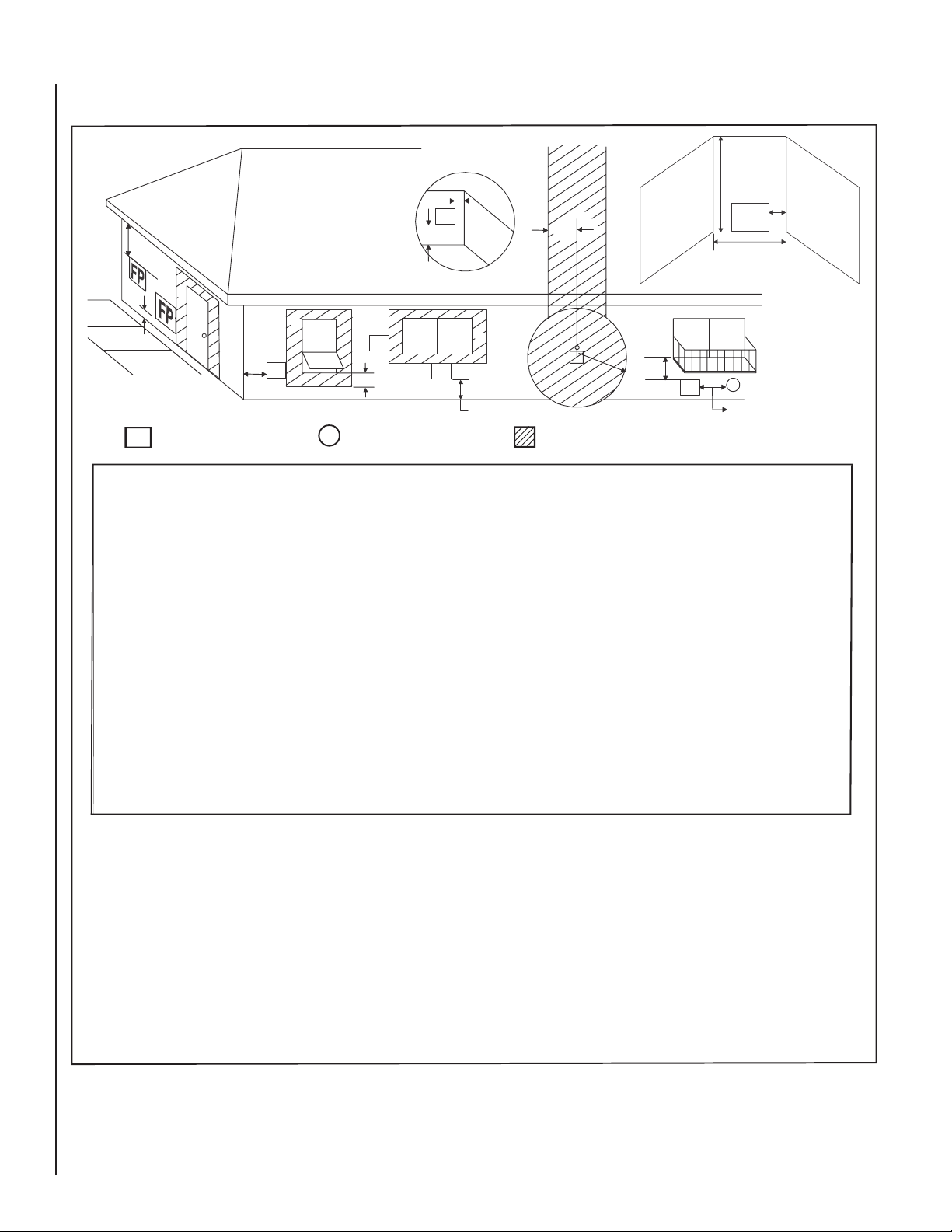
Figure 2
Carefully consider the position of the fireplace
opening with respect to the location of adjacent
or nearby stairwells, doors, windows, walkways
and over hanging trees, patios and wires.
When locating the fireplace, considerationmust
be given to combustibles and final finishing.
See Figure 18 and confine the final location of
combustible finish materials to the "Safe Zone".
Also referto Clearance Specificationson Page 6.
Consider the effects of heat when locating any
object in front of or near the fireplace opening.
PRE-INSTALLATION NOTES
The fireplace may be installed directly on a
combustible oor or raised on a platform of an
appropriate height. Do not place the fireplace
on vinyl or other soft oor coverings. It may,
however, be placed on at wood, plywood,
particle board or other hard surfaces.
Position the electrical junction box as detailed
in LOCATION OF FIREPLACE. (The umbilical
cord is 9 feet long).
Be sure the fireplace rests on a solid continu-
ous oor or platform with appropriate framing
for support.
The fireplace may be positioned and then the
framing built around it, or the framing may be
constructed and the fireplace positioned into
the opening.
Usually, no special oor support is needed for
the fireplace, however, to be certain:
1.Estimate the total weight of the fireplace sys-
tem including surround materials such as brick,
stone, etc., to be installed. Shipping weights for
the fireplace may be found on Page 8.
2. Measure the square footage of the oor space
to be occupied by the system, surrounds and
hearth extensions.
3. Note the decking construction, i.e. 2 x 6’s,
2 x 8’s or 2 x 10’s, single or double joists, type
and thickness of oor boards.
4. Use this information and consult your local
building code to determine if you need ad-
ditional support.
If you plan to raise the fireplace and hearth
extension, build the platform assembly then
position fireplace and hearth extension on
top. Secure the platform to the oor to prevent
possible shifting.
ASSEMBLY STEPS
NOTE: The following steps represent the normal
sequence of installation. Each installation is
unique, however, and might require a different
sequence.
1. Position firebox prior to framing or into
prepared framing (non-combustible framing
is recommended).
2.Position the electrical junction box as detailed
in LOCATION OF FIREPLACE.
(The umbilical cord is 9 feet long).
3.Waterproofthe fireplace or installthe optional
drip pan (see Waterproong The Fireplace and
Figure 3 on Page 5).
4. Plumb gas line. (Gas connections should
only be performed by an experienced, licensed/
certified tradesman.)
5. Complete the installation, finish wall mate-
rial, surround and hearth extension to your
individual taste.
6. Assemble and attach optional accessories.
Study the three dimensional illustration (Fig-
ure 1) to get a general idea of each element
of your fireplace system.
WATERPROOFING THE FIREPLACE
Although the fireplace is designed to operate
safely outdoors, rain may enter the hearth area,
condensation and can cause water to collect
inside the fireplace bottom.
To prevent water collection, the builder must
provide a means to drain water from under
the fireplace by building or installing a water
collector of the builders choice, before posi-
tioning the fireplace in its location.
Special care must be taken when the fireplace is
installed against an exterior wall. The enclosure
surrounding the fireplace on the sides and back
must be treated as an exterior wall.
Innovative Hearth Products (IHP) provides an
optional drain pan to assist weatherproofing
the fireplace.
H4651 DPSS36 Drain Pan for Polaris36, H4652
DPSS42 Drain Pan for Polaris42.
ASSEMBLY OUTLINE
Before You Start
Check your inventory list to be sure you have
all the necessary parts supplied in good usable
condition.Checkalsofor any concealed damage.
LOCATION OF FIREPLACE
Carefully select the proper location for any
obstructions, clearance to side wall(s), air
availability, location and aesthetics. With proper
pre-planning, a slight adjustmentof a few inches
can save considerable time and expense later
during construction and assembly. See Figure
2for some examples.
When choosing a location, care must be taken
to avoid places where ooding or running water
may be a problem.
Identify the desired location for the battery
pack/ON/OFF switch junction box location. This
should be easily accessible and convenient for
use and high enough on the wall to be protected
from water and drifted snow.
Do not use this appliance if any part has been
under water. Immediately call a qualified ser-
vice technician to inspect the appliance and to
replace any part of the control system and any
gas control that has been under water.
Ne pas se servir de cet appareil s'il a été plongé
dans l'eau, complètement ou en partie. Appeler
un technicien qualifié pourinspecter l'appareil et
remplacer toute partie du système decontrôle et
toute commande qui ont étéplongés dans l'leau.
If it is evident that the burner is damaged, the
burner must be replaced with one specified by
the manufacturer before the appliance is put
into operation.
LIVING SPACE
PATIO
Optional
Hearth
Extension