manuals.online logo
Brands
  1. Home
  2. •
  3. Brands
  4. •
  5. AstroMedia
  6. •
  7. Toy
  8. •
  9. AstroMedia Hands-on Science Series Instruction Manual

AstroMedia Hands-on Science Series Instruction Manual

AstroMedia
© Klaus Hünig – Translation: A&A Schröer
The Camera Obscura
foot rest bracket
right side
wall
edging
strip
visor, right side front wall
lens
holder
inner
lens tube
support
outer
lens tube
top cover
and visor
Building instructions
Hands-on Science Series
visor, right side
foot rest
bracket
right
side wall
edging strip
door latch
rear wall
viewing screen
with tracing paper
visor, left side
door with
hinge
top cover and visor
Contents of this kit
The Camera Obscura
The principle of the camera obscura (dark room), the
forerunner of all our photographic and video devices, is
amazingly simple: in a darkened room, a small hole in a
wall creates an upside-down image of the outside world
on the opposite wall.
The picture isn’t very bright because the small amount of
light that comes through the hole is spread over the en-
tire wall, but once your eyes adjust to the darkness, the
picture magically becomes visible. The camera obscura
can be a whole room or just a box where the projection
screen is replaced by a transparent screen so that the im-
age can be viewed from the outside (see sketch).
One might assume that even prehistoric people ob-
served that a small hole in the curtain in front of the cave
opening projects the landscape into the interior. The
camera obscura would therefore be the oldest optical
device known to mankind.
The Mother of all Cameras
Aristotle (384-332 BC) was the rst to study it scien-
tically and Leonardo da Vinci discovered that it copies
the optical principle of our eyes (and the ones of most
vertebrates). In fact, the image on the retina of the eye
is upside down! That we see it the right way up is due to
corrective action in our brain. The pinhole camera, as the
camera obscura is also called when it does not use a lens,
is subject to two laws:
1. The further away the projection screen is from the pin-
hole, the larger and dimmer the image will be.
2. The larger the pinhole, the brighter the image will be,
but also the more blurred it gets.
This severely restricted the possible uses of the camera
obscura, e.g. to the observation of very bright objects
such as the Sun during solar eclipses. The problem was
not solved until the 16th century, when for the rst time
ground glass lenses replaced the simple pinhole. They
admitted more light and made it possible to sharpen
(focus) the image.
But a focusing camera obscura has a dierent disadvan-
tage: the lens cannot focus on objects at dierent dis-
tances at the same time. It has to be pulled out to focus
on close objects and pushed in for objects that are fur-
ther away. A pinhole camera, on the other hand, focuses
on all points of the image equally.
In 1686, Johann Zahn constructed the rst camera ob-
scura which, with the help of a mirror, allowed the ob-
served picture to be traced with a pen on a screen. As a
result, it became popular with painters, who could use it
to easily determine the perspective for their paintings.
The almost photorealistic views of Dresden by the Vene-
tian painter Canaletto from around 1750 are well known.
He used a focusing camera obscura to create them. This
AstroMedia kit works exactly like the camera he used.
In 1826 photography was born when the Frenchman
Nicéphore Nièpce shortened the imaging process by
capturing the picture directly on a light-sensitive plate.
The camera obscura lives on today in the millions of pho-
to and video cameras and, of course, in the miniature
cameras of mobile phones.
However, there are still real camera obscuras in operation
at some tourist attractions (e.g. on the Royal Mile in Edin-
burgh): a large, darkened room in which the outside world
is projected onto a table via a mirror in the roof and so can
be viewed by entire groups at the same time.
This kit contains:
• 4 die-cut sheets of cardboard, 0.65 mm thick
• 4 die-cut sheets of cardboard, 0.4 mm thick
• 1 acrylic glass lens Ø 62 mm, focal length +275 mm
• 1 acrylic glass mirror, 188.5 x 188.5 x 2 mm
• 1 clear viewing screen made of transparent hard
plastic, 190 x 190 mm
• 1 optional diaphragm to cut out
• 3 pieces of tracing paper, 160 x 160 mm
• 1 title page and these building instructions
A detailed photograpic instruction
by Michael Monscheuer can be
found here:
astromedia.de/pdf/
COB-E_Camera_Obscura_BB.pdf
A. The Front Wall and the Side Walls
The walls, base, and viewing window of the camera obscu-
ra form a cube-shaped housing measuring 190 x 190 x 190
mm. Walls and base are made of strong cardboard, the oth-
er parts with visible folded edges are made of more exible
cardboard.
Not absolutely necessary, but helpful:
•For perfectionists: a black and a golden pen to col-
our the white edges of the cardboard.
What you need for assembly:
•Normal all-purpose glue containing solvents, e.g.
UHU, Evo-Stick Impact, B&Q all-purpose glue. Do
not use water-based all-purpose glue or white
glue, they soften the cardboard, warp it and do not
adhere well to plastic parts and the varnished card-
board surfaces. Solvent-based all-purpose glue
also dries much faster.
•Double sided sticky tape for the plane mirror. Some
solvent based glues can damage its reective coat-
ing.
•A small piece of sandpaper (medium to ne) to
roughen the edges of the screen to help the glue
stick to the plastic surface. The craft les from As-
troMedia (order No 400.SBF) are also very practical
for this.
•A sharp craft knife, e.g. the AstroMedia craft knife
(order No 401.MES), or a narrow-tipped scalpel to
cut the thin holding tabs of the pre-punched parts.
•A cutting board or mat, made from hardboard,
plastic, or wood. Self-healing cutting mats are ide-
al, as the material re-closes after each cut.
Please Read Before Commencing:
Tips for successful assembly
The building instructions are divided into 32 small
steps with detailed descriptions. At rst glance, this
looks like a lot of text and a lot of steps, but it makes
assembly easier and faster because each step is
small and easier to understand. Please read each
step from the beginning to the end before com-
mencing and allow yourself about 3 hours for the
construction (depending on experience). The more
care you take, the better your camera obscura will
work and look.
1
Each part has its own name and part number,
consisting of a letter and a number, printed in a
convenient place on the front or back. The letters
denotes the chapter the part belongs to, the num-
bers denote the order of construction. Only remove
the parts from the cardboard as you need them.
2
We recommend that you do not tear the parts out
of the cardboard sheet, but cut through the thin
connecting tabs with a knife to make sure that the
edges are completely smooth.
4
All folding lines are prepared by groves or perfo-
rations. If they are to be bent ‘forwards’, you have to
fold them towards you when looking at the printed
side of the part. If they are to be bent ‘backwards’,
you need to fold them away from you. You get a
straighter fold if you position the folding line over a
sharp edge.
5
The places where something is to be glued are
marked by grey areas. Please note that these glue-
ing areas are usually a bit narrower and shorter
than the part that is to be stuck on. This ensures
that the grey areas will be completely covered. On
each glueing area is a symbol that indicates which
part is to be glued there.
3
All three parts have one edge with a glue tab
that is bevelled on both sides. These edges face up-
wards; the transparent viewing window will later be
glued onto them. Place the front wall [A1] in front
of you with this tab facing upwards, the black inside
towards you. Set up the left side wall [A2] at right
angles to it on the left so that its beveled glue tab
Step 2
is also facing upwards. The black areas of the two
parts then point inwards, the gold-printed areas
outwards (Fig. 1). Check that the rectangular slant-
ed glue area with the 5 arrows on the inside of the
left side wall has its lower end near the front wall.
Glue the front panel in this position to the side glue
tab of the left side panel.
Important: Before drying, press the bottom and side
edges onto your work surface to ensure that they are
level and straight.
Fig. 1: Front and side walls
A2
A1
A3
Detach the front wall [A1, sheet 1], the left
side wall [A2, sheet 3], and the right side wall [A3,
sheet 4] from the cardboard sheets. Also detach the
octagonal base panel [C5] from the front wall, you
will need it in section C. The small disc in the base
panel[C5] should notberemovedbecause although
it is punched during the production process it is not
needed. Fold all glue tabs backwards along the per-
forations, i.e. towards the black back.
Tip: This is how to fold the 0.65 mm thick cardboard
neatly: Place the part on a board or similar with a sharp
edge so that the perforated fold line is lying on the edge
and bend the glue tab downwards. Then fold it all the
way over and smooth the fold with your thumbnail or
a folding tool.
Step 1
Important: “Front” is where the camera obscura has its lens,
“back” is where its back wall with the small door is located.
“Left” and “right” then follow automatically. The observer
stands behind the camera obscura and points the lens to-
wards the object whose image is to be captured.
Fold the 3 glue tabs of the right side wall
[A3, sheet 2] backwards as well and glue the right
edge of the front wall to the glue tab in the same
way. Now the three walls form part of a box with the
base, back wall, and lid missing.
Step 3
Hold the outer lens tube horizontally and
turn it so that the side with the connecting piece
is facing downwards. Slide the foot tabs through
the octagonal opening in the front panel from the
outside and glue them to the glue marks located
around the opening.
Tip: Press the inside of the front wall onto your work
surface to push the foot tabs in place.
Step 5
Four supports are required to stabilise the
connection between the outer lens tube and the
front wall. Fold the foot tabs of the 8 support parts
[B4 to B11, sheets 1 to 4] forwards and glue each two
of them back to back to form four angled supports
with two foot tabs on one edge. As a test, rst place
one of the supports with its foot tabs on one of the
glue marks on the outside of the front wall and push
it against the outer lens tube. The edge of the sup-
port without tabs butts against the wall of the tube.
Apply glue to the foot tabs and to the blunt edge
and glue the support in this position. Glue the oth-
er three supports in place the same way. The lower
support is glued to the connecting piece that holds
the outer lens tube together.
Step 7
B. The Outer Lens Tube
The outer lens tube serves as a guide for the inner lens tube,
which will be built in Section D. The inner lens tube can be
moved back and forth inside the outer lens tube so that the
objective lens can be focused on objects at dierent dis-
tances.
Remove the outer lens tube [B1, sheet 5]
from the cardboard and fold all 8 long groove lines
backwards. When you butt the edges of the two
half-segments at the ends of the piece of cardboard
together, a short octagonal tube is created that is
black on the inside. The small glue tabs marked in
grey are the foot tabs with which the tube will be at-
tached to the inside of the front wall. They all need
to be folded forwards towards the gold printed side.
In order to turn the folded piece of cardboard into
a stable octagonal tube, you need the connecting
piece [B2, sheet 7]. Glue it to the outside of one half
segment so that it sticks out exactly half way, then
glue it to the the other half. This works particular-
ly well if you press the tube at, so that both edges
are pushed against each other without a gap. Make
sure there is about a millimetre of space between
the connecting piece and the foot tabs.
Step 4
Fold the two mirror mounts [A4 and A5,
sheet 6] backwards at right angles. This creates
two angled strips that are black on the inside and
grey on the outside. Glue the mirror holders onto
the two glue marks located on the inside of the left
and right side walls.
Important: The folded edges must be exactly ush
with the edge of the glue marking to which the arrows
are pointing. The mirror itself will be installed in Sec-
tion E-2.
Step 8
Fold the grooved lines of the edge rein-
forcement [B3, sheet 5] backwards and glue it onto
the glue marks around the opening of the outer
lens tube. The seam where the ends of the edge re-
inforcement meet should be at the bottom of the
outer lens tube.
Step 6
Fig. 2: Outer lens tube
B2
B1
C. The Base Panel
The base panel has glue tabs on all four sides. It consists of
four trapezoidal parts and the octagon detached from the
front wall. These ve parts are glued together on the back
with eight connecting pieces (Fig. 3). On the side facing the
inside of the housing, all parts are black, including the con-
necting pieces.
C10
C5
C12
C3
C11
C2
C7
C13
C8
C4
C1 C6
C9
Fig. 3: Base panel
way using the large connecting pieces and nally
glue the small connecting pieces to the remaining
free edges of the octagon (see Fig. 3).
Detach the round centre cover [C14, sheet 7]
from the cardboard. The ring between parts D3 and
C14 is not needed and can be discarded. Glue the
cover onto the outside of the octagonal centre sec-
tion of the base panel. This covers the small round
disc that was not removed.
Step 13
Remove the base panels 1 to 4 [C1 to C4,
sheets 1 to 4] from the cardboard, as well as the
large connecting pieces 1 to 4 [C6 to C9, sheets 1
and 2] and the small connecting pieces 5 to 8 [C10
to C13, sheets 1 to 4]. The octagonal central base
panel [C5] was left over from Step 1. Fold the long
glue tab on oor panels 1 to 4 backwards.
Step 9
Place the octagonal base plate [C5] with the
black side facing up in the gap provided so that one
of the narrower glue marks is under the protruding
end of the connecting piece and all edges butt to-
gether without gap. Glue the part to the connecting
piece. Now attach the other base panels in the same
Step 11
First place two of the trapezoidal base
plates with the black side facing upwards on your
work surface so that the sloping edges meet and
half an octagon is formed in what is going to be the
centre.Glueone ofthe largerconnectingpiecesover
the joint. The pointed end of the connecting piece
points to the corner and the blunt end protrudes a
little into the area of the octagon. Make sure that
the edges of the base plates meet without a gap and
that the black side of the connecting piece is facing
upwards.
Step 10
Check that the space where you can write
your name and the year of manufacture faces the
direction you want (towards the front or back of
the camera obscura). Fold the glue tabs of the base
plate backwards again and push them between the
two side walls of the housing until they touch the
front wall. Then glue the bottom panel to the front
wall. Push the front wall onto the work surface so
that the base is ush with its bottom edge. As a test,
push the two side walls against the base and check
that the base sits exactly in the middle. Then glue
the side walls to the glue tabs on the base panel.
Step 12
Remove the lens holder [D3, sheet 7] from
the cardboard and fold all 8 glue tabs backwards. The
enclosed acrylic glass lens is used as the objective
lens. It has one curved side that points towards the
object, the other side is at and faces towards the
inside of the camera obscura. Handle the lens by the
edges only and, if necessary, wipe ngerprints o
withasoft cloth (don’tuse tissue paper,as it scratch-
es the surface). Place the lens holder with the black
inside facing up on your work surface or, even bet-
ter, on top of a small cup and try the lens on it with
the curved side facing down. Remove the lens again
and coat the lens holder with glue around the hole to
a width of about 3mm. Check that no threads of glue
have formed across the opening, then carefully place
the lens on top and centre it. Leave to dry completely.
Step 15
Fold all groove lines of the inner lens tube
[D1, sheet 5] backwards. Again, an octagonal tube,
black on the inside, is formed with the two half seg-
ments touching. Connect the two half segments on
their inside with the connecting piece [D2, sheet 5].
Make sure that the edges of the half segments butt
against each other without a gap and that the black
surface of the connecting piece faces towards the
inside of the tube.
Step 14
D. The Inner Lens Tube
The inner lens tube has a slightly smaller diameter than the
outer one and houses the objective lens.
The housing is now complete, except for the top cover. It will
gain its stability in the next step, when the mirror is tted
inside and the viewing window is tted to the top.
Fold the two door handle parts [E7 and E8,
sheet 7] forwards and glue one half of each back
to back. Then glue the resulting handle with the
other two halves onto the grey back of the bar [E6,
sheet 7].
Step 19
Place the lens holder on the end of the in-
ner lens tube with the glue marks and glue its tabs
to the tube. After drying, check that the inner tube
can be pushed back and forth inside the outer tube.
Then put it aside so that the lens is not damaged
during the rest of the assembly. Tip: If, despite all
caution, you have a mishap with the lens, you can order
a new one from AstroMediaShop.co.uk (OptiMedia lens
no. 10, article No. 314.OM10).
Step 16
Remove the small disc-shaped bar shaft
[E5] from the door [E2, sheet 2].Glue the shaft onto
the grey glue marking of the interior bar so that it
sits in the centre of the semi-circle forming the end
of the inner bar. Leave to dry well.
Step 18
Lay the rear wall [E1, sheet 2] black side
down onto your work surface and put the door in
the doorway. The bar is turned all the way to the left
so that it does not protrude over the door. Fold the
door hinge [E9, sheet 7] forward once and then at
again and glue it onto the glue marks located on the
door and door frame. The fold should lie exactly on
the die-cut line. After drying, check the door func-
tions (opening, locking).
Step 21
Detach the door [E2, sheet 2] from the
rear wall and lay it black side down onto your work
surface. Place the inner bar under the door so that
the disc-shaped bar shaft snaps into its hole in the
door from below. Rotate it a bit so that the axle can
grind into its bearing a little, then turn it so that the
visible part protrudes at right angles from the door.
Put a small amount of glue on the shaft and stick
the door bar with its glue mark onto it. It points
in exactly the same direction as the inner bar, but
is slightly shorter than this. This is intentional to
make it easier to close. Allow the glue to dry thor-
oughly and then carefully move the latch back and
forth until it can be rotated around fully.
Step 20
Fold the glue tab of the rear wall backwards
and again fold the three glue tabs of the side walls
and oor, to which the rear wall is glued. Open the
door latch and push the door partly through the
door opening. This way the door handle does not
get in the way when the rear wall is placed on the
work surface to be pressed. Glue the rear wall to the
glue tabs on the base panel and side walls. Its own
glue tab is pointing upwards, just like those on the
other housing walls. Again, make sure that all edges
are ush with the other walls. To dry, lay the case on
its back and put a light weigh on it, e.g. a book.
Step 22
door
E2
Glue the two parts of the interior bar [E3
and E4, sheet 7] with their grey sides back to back,
accurately aligned at the edges (Fig. 4 shows a
cross-section of the bar and door).
Step 17
E1. The Door and the Rear Wall
In the rear wall is a small door that can be locked with a ro-
tating bar so that pencils and rolled-up sheets of transparent
paper can be stored in the space below the mirror. First the
door is assembled, then the door is mounted in the rear wall
and the rear wall is tted to the housing.
handle
interior bar
E7 E8
E3
E4
E6
Fig. 4: Cross-section rotating bar
E2. The Mirror and the Viewing Screen
Without a mirror, the image would fall onto the back wall
of the housing and would be upside-down. Reecting the
image upwards at right angles with a mirror results in an
upright mirror image. The viewing window alone does not
display the image because the light goes straight through
it. But when a piece of semi-transparent paper (tracing pa-
per) is placed on top, the image appears.
F. The Edging Strips
The 12 edging strips cover the glued edges of the hous-
ing and increase its stability. Four of them [F7, F8, F10 and
F11] have punched cut-outs that will later accommodate
the footrests of the visor. The places to which they are to be
glued are indicated by the accordingly shaped glue mark-
ings. The edging strip [F9] has a glue mark on its outside. It
is used to attach the top cover, which also serves as part of
the visor.
As a test, place the mirror with the protec-
tive foil facing upwards into the housing from above
so that its side edges are ush with the two mirror
supports. Its upper edge is pretty close to the future
cover, the distance between the lower edge and the
base panel is signicantly larger. Refold the mirror
supports so that they are perpendicular to the side
walls and glue the mirror in place. Push the side
walls together lightly and make sure the top open-
ing of the case is square before the glue sets. This
can be checked easily with the help of the trans-
parent viewing screen, by placing it temporarily in
its future position on top of the glue tabs. Allow to
dry thoroughly and then remove the protective lm
from the mirror.
Step 23
Using a craft le or sandpaper, roughen all
four edges of the viewing screen to a width of about
1 cm on both sides, so that the glue adheres better
to the plastic. If you don’t have sandpaper, you can
scratch the edges with a sharp object, but be careful
not to scu or scratch the viewing area. Then fold
the glue tabs of the housing again so that they are
horizontal. Glue the viewing screen onto the hous-
ing and check that it does not protrude on any side.
Weigh the screen down while the glue sets, e.g. with
a book.
Step 24
Fold all edging strips 1 to 12 [F1 to 12, sheets
5, 6 and 8] sharply backwards. Make sure the fold
goes precisely through the pointed ends. Glue the
edging strips [F1 to F4] to the four edges of the base
panel, then the edging strips [F5 and F6] to the two
vertical edges on the right and left of the rear wall.
Their pointed ends should touch without gaps and
their tips meet at the corners of the housing.
Step 25
Next, glue the edging strip that has the
grey glue marking [F9] onto the upper front edge of
the housing above the lens. The half with the glue
marking is glued onto the viewing screen. Then
glue the edging strip [F10] to the upper left edge
of the housing. The punched cut-out should be on
the back of the left side wall, towards the back wall,
as the glue marking indicates. Correspondingly,
the edging strip [F11] is glued onto the edge of the
housing at the top right. The last strip [F12] then
lls the last free space at the top back.
Step 27
Glue the edging strip [F7] to the edge
formed by the front wall and the left side wall in
such a way that the half-oval cut-out is positioned
at the bottom of the left side wall, as indicated by
the glue marking. Then glue the edging strip [F8] to
the front right edge of the housing accordingly.
Step 26
Fold the glue tab on the right side of the vi-
sor [G2, sheet 7] backwards and glue the grey sur-
face of the foot rest 1 [G3, sheet 7] to the marked
spot on the black back of the side part of the visor
(Fig. 5). The foot rest should be ush with one edge
of the visor side part and on the other side the gold
printed semicircular end protrudes beyond the
edge. Then glue the right visor part with its tab onto
the right hand edge of the top cover. At the rear it
should be ush with the end of the top cover. At the
front it just reaches the bend of the cover’s hinge.
Step 29
Fold the glue tab on the top cover [G1, sheet
6] forwards and then glue this tab to the marked
spot located at the top of the front edge strip. Make
sure that the cover sits in the middle of the housing
and is ush with the edges of the housing when it is
closed.
Step 28
To enable the top cover to be secured in a
60° position, two further brackets are provided for
the foot rests. They are glued at an angle onto the
side walls. Glue the four bracket feet [G10+11 and
G13+14, sheet 3 and 4] under the ends of the foot
rest brackets [G12 and G15, sheet 7] and then glue
these onto the angled glue markings on the right
and left side wall. Before the glue sets, check that
the foot rests of the visor t neatly into place.
Step 32
G2
G3
If you now open and close the lid, you will see
that the foot rests on the sides of the visor t into
the cut-outs in the edging strips. To enable them
to latch in those positions, brackets are glued over
the cutouts. Glue the 4 foot rest brackets 1 to 4 [G6
to G9, sheet 5] over the cut-outs in the front and
the top edging strips so that they are ush with the
edges of the edging strips. This creates pockets in
which the foot rests can be inserted and the lid can
be secured either closed or open at right angles.
Step 31
Glue foot rest 2 [G5, sheet 7] to the left side
of the visor [G4, sheet 7] in the same way and then
glue it to the left edge of the top cover.
Step 30
Fig. 5: Visor side part with foot rest
Congratulations!
Your camera obscura is now complete. Place a sheet of trac-
ing paper on the viewing screen and it’s ready to use.
G. The Top Cover and Visor
To make the image on the tracing paper easier to see, the top
of the Camera Obscura can be shaded by a visor. The top cov-
er acts as the front of the visor. The side visor parts have foot
rests that can be slid into brackets at dierent heights.
Photo prints of your drawings
The camera obscura is not suitable for direct exposure
of photographic paper, but you can make very impres-
sive photographic prints from pencil drawings you made
on the tracing paper. There is a simple method without
having to use a darkroom or chemical developers. Take
a sheet of AstroMedia’s Solar Photo Paper (article No.
411.FSP) and place the front side of the sketch, which
is mirror-inverted, on the photo paper when exposing.
When developing (with normal tap water!), a white neg-
ative appears on a dark blue background, now showing a
right-sided image.
The Camera Obscura as a pinhole camera
Your Camera Obscura can also be turned into a pinhole
camera. To do this, remove the inner tube with the lens
and cover the outer tube with dark paper, in which you
have pierced a hole.
Start with a small hole (approx. 1 to 2 mm), which you can
then gradually enlarge. Cover yourself and the screen as
lightproof as possible with a dark cloth and allow your
eyes to adjust to the darkness. Unlike those obtained
with the lens, the images you see have a continuous
depth of eld – which is the great advantage of pinhole
cameras. However, the picture is also much darker. The
bigger the hole, the brighter, but also the blurrier the
image becomes.
Tips for using the camera obscura:
Make sure that the subject is well lit and that
the camera obscura itself, especially the tracing pa-
per screen, is in the shade or in the dark.
Tip 1
If the inner lens tube moves too easily, you can
glue some strips of (black) paper into the outer tube
to make the t tighter.
Tip 3
The lens has a large aperture and with a focal
ratio of 4.8 a high light intensity. The focal ratio or
f-number is calculated by dividing the focal length
of 275mm by the 57mm lens diameter. A trade-o
for the bright picture is the low depth of eld, i.e.
onlyobjects thatareata similardistance areimaged
sharply. By moving the lens in or out you can adjust
the camera to dierent distances. You can increase
the depth of eld by reducing the lens aperture with
a diaphragm made from dark cardboard. The small-
er the diaphragm, the larger the depth of eld and
the dimmer the image will be.
Tip 5
You can see the picture more clearly by cov-
ering yourself and the screen with a dark cloth or a
piece of clothing.
Tip 2
Unwanted reections, which cannot be avoid-
ed despite the black inner walls, can be greatly re-
duced with the additional diaphragm provided. Cut
it out of the cardboard and fold the eight tabs back-
wards. Push the diaphragm, octagon rst, into the
open end of the inner lens tube, opposite the lens,
until the tabs are ush with the edge of the tube.
You can secure it in this position with a few drops of
glue or, if you want to experiment with other dia-
phragm sizes, just leave it loose.
Tip 4
The lens cannot be pulled out far enough for
very close objects. However, you can get around this
with a makeshift extension made of black paper,
which you fold into a suitable octagonal tube and
insert between the inner and outer lens tubes.
Tip 6
AstroMedia
Understand science with our
fascinating and fully functional
cardboard kits
THE SOLAR
PROJECTOR
Solar Eclipse Cinema
A projector to safely watch solar
eclipses, planetary transits, or sunspots
THE NITINOL
ENGINE
Fuel: Hot Water!
When this engine starts to turn
tirelessly and at high speed, it attracts
astonished and puzzled looks.
THE STEAM
ENGINE
A fascinating classic
A cleverly constructed steam conduit makes
it possible to power this cardboard machine
with water that is boiled by tea lights.
THE STIRLING
ENGINE
A cup of tea or coee is all it takes
When you put this stirling engine on
top of a hot cup of tea, it transforms the
heat into rapid rotary motion.
Hands-on Science Series
COB-E-3230

This manual suits for next models

1

Other AstroMedia Toy manuals

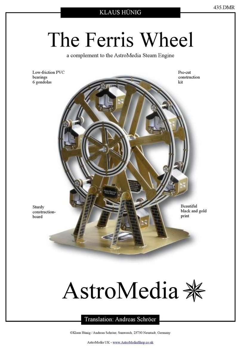
AstroMedia The Ferris Wheel User manual

AstroMedia

AstroMedia The Ferris Wheel User manual

Popular Toy manuals by other brands

Fisher-Price Little People Circus Friends Gift Set instructions

Fisher-Price

Fisher-Price Little People Circus Friends Gift Set instructions

Kavan CUMUL DLG instruction manual

Kavan

Kavan CUMUL DLG instruction manual

Fisher-Price H6430 instruction sheet

Fisher-Price

Fisher-Price H6430 instruction sheet

Fisher-Price PowerMax Rescue Heroes Hal. E. Copter manual

Fisher-Price

Fisher-Price PowerMax Rescue Heroes Hal. E. Copter manual

Fisher-Price Bigfoot the Monster instruction sheet

Fisher-Price

Fisher-Price Bigfoot the Monster instruction sheet

Eduard Zoom Victor B Mk.2 (BS) quick start guide

Eduard

Eduard Zoom Victor B Mk.2 (BS) quick start guide

Krick 20310 instructions

Krick

Krick 20310 instructions

Hasbro Gaming Blowfish Blowup manual

Hasbro Gaming

Hasbro Gaming Blowfish Blowup manual

VTech Baby Snooze & Soothe Elephant Parents' guide

VTech Baby

VTech Baby Snooze & Soothe Elephant Parents' guide

Hacker RT SUPER SIRIUS Mounting and operation manual

Hacker

Hacker RT SUPER SIRIUS Mounting and operation manual

GWS PT-17 instruction manual

GWS

GWS PT-17 instruction manual

MTHTrains HO 4-8-8-2 Cab Forward Steam Engine Engineer's guide

MTHTrains

MTHTrains HO 4-8-8-2 Cab Forward Steam Engine Engineer's guide

Backyard Discovery Cedar Chateau 6511 owner's manual

Backyard Discovery

Backyard Discovery Cedar Chateau 6511 owner's manual

marklin 36711 user manual

marklin

marklin 36711 user manual

Educational Insights GeoSafari Jr EI-5112-P manual

Educational Insights

Educational Insights GeoSafari Jr EI-5112-P manual

marklin BR 44-OI manual

marklin

marklin BR 44-OI manual

Modelbouw Atelier Apeldoorn CASPER Owner's handbook

Modelbouw Atelier Apeldoorn

Modelbouw Atelier Apeldoorn CASPER Owner's handbook

advanced scale models P-61 Black Widow Assembly instructions

advanced scale models

advanced scale models P-61 Black Widow Assembly instructions

manuals.online logo
manuals.online logoBrands
  • About & Mission
  • Contact us
  • Privacy Policy
  • Terms and Conditions

Copyright 2025 Manuals.Online. All Rights Reserved.