manuals.online logo
Brands
  1. Home
  2. •
  3. Brands
  4. •
  5. Astronomy Technologies
  6. •
  7. Telescope
  8. •
  9. Astronomy Technologies AT8RC User manual

Astronomy Technologies AT8RC User manual

1
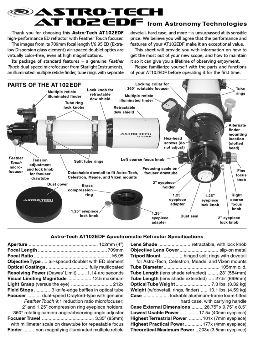
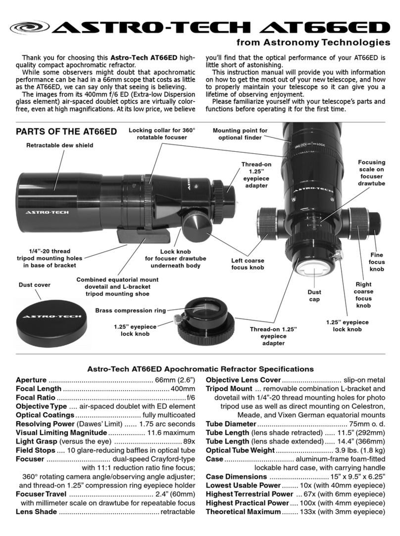
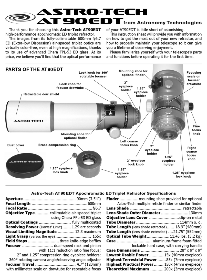
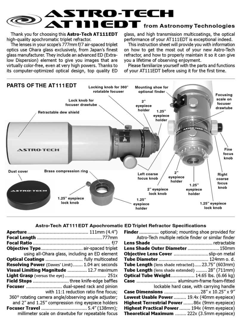
Thank you for choosing this Astro-Tech AT8RC 8” f/8
Ritchey-Chrétien astrographic reflector.
Your AT8RC is designed for coma-free imaging using DSLRs
and CCD cameras. It is particularly good with systems
involving long imaging equipment chains (CCD camera, filter
wheel, adaptive optics system, electric focuser, etc.)
These instruction sheets will provide you with information
on how to get the most out of your new Ritchey-Chrétien
reflector, and how to properly maintain your telescope so it
can give you a lifetime of quality imaging.
Please familiarize yourself with your astrograph’s parts and
functions before operating it for the first time.
astro-tech
AT 8 R C
from Astronomy Technologies
Lock knob
for focuser
drawtube
PARTS OF THE AT8RC
1.25” accessory
lock knob
Right coarse
focus knob
Fine
focus
knob
Mounting shoe for
optional finder
Locking collar for
removable 360°
rotatable focuser
Thread-on
extension
rings
Aperture .................................................... 203mm (8”)
Focal Length .................................................. 1625mm
Focal Ratio ............................................................... f/8
Optical Type .............................. dual hyperbolic mirror
true Ritchey-Chrétien reflector
Mirrors .......................... low thermal expansion quartz,
99% reflectivity dielectric multicoatings
Secondary Mirror Holder Obstruction ............. 95mm
(47% by diameter, 22% by area)
Field Stops .................... ten internal knife-edge baffles
Tube Diameter............................... 9.02” (229mm) o. d.
Tube Length (without focuser) ................ 18.5” (470mm)
Tube Length (with focuser) ....................... 22” (560mm)
Astro-Tech AT8RC Ritchey-Chrétien Astrograph Specifications
Tube Weight (without focuser) ........... 14.8 lbs. (6.73 kg)
Tube Weight (with focuser) ................ 16.4 lbs. (7.45 kg)
Mounting System ........ one 15.5” Vixen-style dovetail,
one 15.5” Losmandy-style “D-plate” dovetail
Focuser ............ removable dual-speed linear Crayford
with 10:1 reduction ratio fine focus;
2” and 1.25” compression ring accessory holders;
360° rotating camera angle/observing angle adjuster
Focuser Mounting Thread ......... 90mm x 1mm metric
Focuser Travel ....................................... 1.97” (50mm)
Focuser Extension Rings ....... two 25mm, one 50mm
Finder ........ none; mounting shoe provided for optional
Astro-Tech multiple reticle finder or similar finder
Collimation
screws
Secondary mirror
holder and baffle
Vixen-style
dovetail
1.25” compression
ring accessory adapter
2” compression
ring accessory
holder
Drawtube
tension knob
(underneath)
Carbon fiber
tube
2” accessory
lock knob
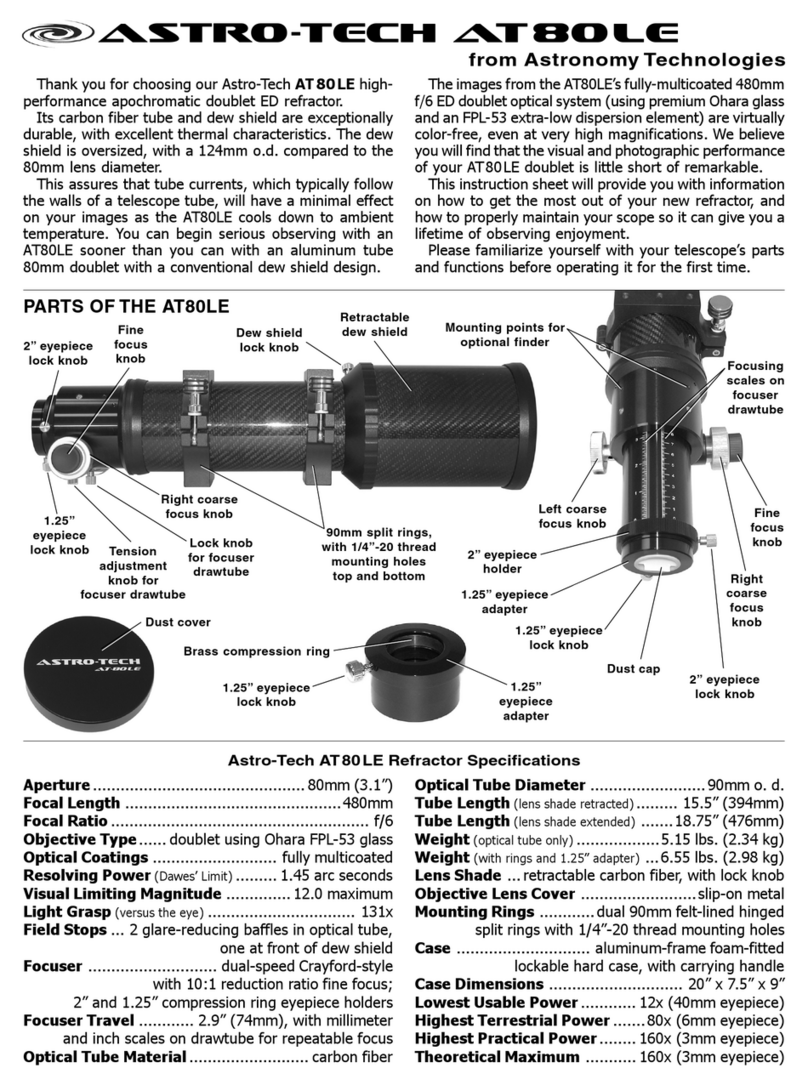
Components of the Focusing System: Your AT8RC has
a 2” Crayford focuser with a 2” compression ring accessory
holder on the focuser drawtube. There is also a separate 1.25”
compression ring accessory holder that can be slipped into
the drawtube’s 2” holder. These allow you to use either 1.25”
or 2” photographic accessories with no other adapters needed.
To minimize drawtube flexure under heavy loads during
imaging, the drawtube travel of the removable AT8RC fo-
cuser is kept short, at 50mm. To make up for the longer back
focus and lengthy all-purpose drawtube travel found in scopes
used both visually and for imaging (typically 80mm to 135mm
or more), the AT8RC focusing system has several compo-
nents, as shown in the illustration on the next page. They
consist of a removable 2” linear Crayford focuser that is
threaded onto the scope’s rear cell when you receive your
AT8RC and three thread-on extension rings (two 1” and one
2”). The rings can be installed singly or in combination be-
tween the focuser and the AT8RC’s rear cell. They provide a
flex-free solid metal focuser extension to take up any un-
needed back focus.
Left coarse
focus knob
Vixen-style
dovetail on
top of tube;
Losmandy-style
“D-plate”
dovetail
underneath
2
The focuser is used by itself or (more typically) in combina-
tion with one or more extension rings to place your camera at
the telescope focal plane. Many long equipment train imaging
setups will require either one or no extension rings. Two or
three extension rings will generally be needed for imaging
with a CCD that is used without other accessories and with
DSLRs. A little experimentation will be called for to determine
what combination of focuser and extension ring(s) will be
needed for your particular combination(s) of components.
In some rare cases, there may not be enough focuser ex-
tension even when using all three extension rings. Astro-Tech
makes optional thread-on extension rings in 1” and 2” lengths
that can be used along with the three supplied extension rings
to add the extra non-flexing focuser length needed.
Be careful not to cross-thread any of the focuser
components when and if changing them in the dark.
The Crayford Focuser: The backlash-free linear drive
Crayford focuser has dual-speed focusing. There are two coarse
focusing knobs. The right knob also has a smaller concentric
knob with a 10:1 reduction gear for microfine focusing. This
provides very precise image control during critical CCD/DSLR
imaging. The focus knobs have ribbed gripping surfaces so
they are easy to adjust, even while wearing gloves or mittens
in cold weather.
There are two chrome lock knobs on the focuser, as shown
in the illustration above. The smaller bottom knob (in the
housing between the focus knobs) adjusts the tension on the
Crayford focuser drawtube to accommodate different weight
equipment loads without focuser slippage.
This tension lock
knob should always be tightened firmly, even with a
light equipment load, to avoid drawtube flexure.
The larger top knob (by the Astro-Tech logo) locks the fo-
cuser drawtube in place by disengaging the focusing knobs
once the correct photographic focus has been reached.
Rotating the Focuser: Your AT8RC focuser can be ro-
tated a full 360° for the best photographic composition prior
to critical focusing. To rotate the focuser, loosen the ribbed
aluminum focuser rotation lock ring (shown above) by turn-
ing the ring slightly counterclockwise. This ring also connects
the focuser to the telescope rear cell or to an extension ring.
Adjust the focuser to the desired angle. Then turn the lock
ring back in the opposite direction to lock the focuser in its
new orientation. It is best to adjust the focuser orientation
before fine-tuning the focus and locking the drawtube.
Extension
rings
Crayford
focuser
THE PARTS
OF THE AT8RC
FOCUSING
SYSTEM
Rear
cell
Top lock knob:
locks drawtube in place
Bottom lock knob:
adjusts drawtube tension
The AT8RC FOCUSER LOCKS
Mounting Your AT8RC: The underside of the AT8RC has
a 15.5” long Losmandy-style “D-plate” dovetail rail running
from front cell to rear cell. This will let you install your AT8RC
on any high-payload equatorial mount that uses a Losmandy-
style dovetail to hold a telescope. You can also use the dove-
tail rail to piggyback your AT8RC on a larger scope using any
accessory mounting system that uses Losmandy-style dove-
tail adapters.
There is also a 15.5” long Vixen-style dovetail running from
front cell to rear cell on top of your AT8RC. If you have mounted
your AT8RC directly on an equatorial mount using the
Losmandy-style dovetail bar on the underside of the scope,
this Vixen-style dovetail will let you mount accessories (such
as Astro-Tech photoguide rings) on top of your AT8RC.
You can also invert your AT8RC to put the Vixen-style dove-
tail on the bottom. This lets you install your AT8RC on one of
the many lighter-payload equatorial mounts that use a Vixen-
style dovetail to hold a scope. Either way, the long length of
the dovetail rails makes it easy to balance your AT8RC (and
gives you the room to add optional counterweights at the
nose of the AT8RC to balance long equipment trains, if needed).
Finderscope: No finderscope is provided, due to the pho-
tographic nature of the AT8RC. However, a rear cell mounting
shoe is provided that will hold an optional Astro-Tech #ATF
illuminated multireticle finder, or any similar red dot finder or
refractor-type finder that will fit the mounting shoe.
Caring for Your Scope Finish: The body of your AT8RC
is made of low thermal expansion carbon fiber cloth encapsu-
lated in a clear epoxy shell. Automotive-grade paint is used
on the aluminum front and rear cells. The focuser and dove-
tails are anodized. All of these very durable surfaces can be-
come smudged with fingerprints during use, but these will
not harm the finishes. A little moisture from your breath and
a quick wipe with a clean handkerchief is generally enough to
remove the fingerprints. Avoid harsh chemical cleaners or or-
ganic solvents like benzene, acetone, etc., as these may af-
fect the clear epoxy finish.
Cleaning Your Scope Optics: Because the mirrors are
protected by the optical tube and dust covers, they will rarely
(if ever) need cleaning. Small amounts of dust on the mirrors
will not appear in the image or block enough light to be an
issue and can be safely ignored. If you absolutely feel you
must
clean the optics, however, you can do so
at your own
risk,
but it is
not
recommended. You will have to disassemble
the optical tube to do it, and recollimate it afterwards. This
can often result in an inadvertent change in the image-critical
factory-fixed spacing between the primary and secondary mir-
rors that will affect your performance.
Any damage or mirror-spacing changes to your
AT8RC sustained during an attempt to disassemble and
clean the optics is not covered by warranty.
Collimating Your AT8RC Optics: Your Astro-Tech AT8RC
Ritchey-Chrétien’s primary and secondary mirrors were colli-
mated at the factory before being shipped. Nevertheless, rough
treatment in transit could potentially cause the secondary mir-
ror to be knocked out of collimation, and rough and bumpy
roads during transit to a dark sky observing site might require
periodic re-adjustments. The optical axis of the primary mir-
ror/baffle tube assembly is less likely to be knocked out of
collimation, but is capable of being collimated if needed.
Preliminary Collimation Check: You can roughly check
the collimation of both mirrors indoors before performing a
more rigorous star test for a final tweaking in the field. You
will need a Cheshire eyepiece to do this collimation check.
Set up your scope in a well-lit room with the telescope
pointed horizontally. Remove the lens cover and point the
Ribbed focuser rotation lock ring
3
Viewing aperture
in center of
Cheshire eyepiece
Reflective surface
of Cheshire
eyepiece
Secondary mirror
spider vane
Secondary
mirror in its
holder
Reflection of the
interior of central
baffle tube; the
glare stop baffles
are visible as light
concentric rings
Figure 1:
View through a
Cheshire eyepiece
(not to scale)
Viewing aperture is
off center in reflective
surface of Cheshire
Figure 2:
Secondary mirror
out of collimation
(not to scale)
Secondary mirror is
centered when viewed
through Cheshire
End of focuser
drawtube (optical axis)
Surface of
room wall
Front end of
optical tube
Front end of
optical tube
End of focuser
drawtube (optical axis)
SECONDARY
MIRROR
COLLIMATION
SCREWS
Collimation screws
(4mm hex head)
DO NOT ADJUST
CENTER
PHILLIPS-HEAD SCREW
DO NOT
ADJUST
Matte black interior
of optical tube
telescope at a white (or light colored) wall. Remove all of the
extension rings and attach the focuser directly to the optical
tube. Insert the Cheshire eyepiece fully into the focuser using
the 1.25” eyepiece adapter. Lock the focuser drawtube firmly
in place. Make sure there is a light source directed at the 45°
cutout in the side of the Cheshire.
Look through the Cheshire eyepiece. You will see a small
black dot within a centrally-located bright circle as seen in
Figure 1, above. The central black dot is the viewing aperture
in the center of the Cheshire eyepiece. The bright circle around
the central dot is the 45° reflective surface of the Cheshire
eyepiece and the larger black circle surrounding that is a
reflection of the interior of the scope’s baffle tube in the
secondary mirror. Your room wall and the interior of the optical
tube form the background.
Concentric light-colored rings will be visible in the black
circle of the secondary mirror if your room and the light source
aimed at the cutout in the side of the Cheshire are bright
enough. These are the reflections from the glare stops
machined into the baffle tube interior. You are seeing the front
of the glare stops that face the sky and their visibility here
simply shows that they are doing their job of reflecting stray
light back at the sky.
The outermost ring of light around the entire Cheshire field,
as shown in Figure 1, is the end of the focuser drawtube (the
optical axis of the scope). You can disregard this for the time
being. It will be covered later, when checking the primary
mirror collimation.
If the central black dot (the viewing aperture of the eyepiece)
appears centered in the circular reflective surface of the
Cheshire eyepiece as shown above, no further significant
adjustment of the secondary mirror will be necessary.
Secondary Mirror Collimation: However, if the black dot
of the viewing aperture appears off-center as in Figure 2, at
the top of the next column, adjust the three secondary mirror
collimation screws shown below until the viewing aperture is
centered as closely as possible in the Cheshire’s circular
reflective surface.
A user-supplied 4mm hex key is required to collimate the
secondary mirror. Adjust only the three hex head screws around
the perimeter of the holder, as shown in the illustration in the
previous column.
Do not adjust the center screw.
Adjusting
the center screw can cause the secondary mirror to fall off
and any resulting damage will not be covered under warranty.
As you adjust each of these screws you will need to make
equal counter-adjustments to the other two. In other words,
as you tighten one screw you will need to loosen, by an equal
amount, the other two. The opposite is also true. If a screw is
loosened, the two opposing screws should be tightened. When
the process is complete you should have equal tension on all
three screws.
Only minor adjustments should be required to fine-tune
the collimation. Adjust the screws no more than an eighth of
a turn or less at a time. This will help prevent accidently putting
the optics grossly out of collimation. The force vector diagram
on the next page will show you how different adjustments
affect the tilt of the secondary mirror.
The correct alignment of the secondary mirror is critical in
determining if the optical axis (primary mirror) requires
alignment. Be certain you have properly aligned the secondary
mirror before proceeding to the next step of adjusting the
optical axis collimation, using the primary mirror collimation
screws shown below.
Optical Axis (Primary Mirror) Collimation: As
mentioned above, the optical axis of the scope (the primary
mirror/baffle tube assembly) will rarely need collimation. If
the optical axis does get knocked out of collimation, however,
the image through the Cheshire eyepiece will appear to be
shifted to one side within the light ring formed by the end of
the focuser drawtube, as shown in Figure 3 on the next page.
If properly collimated, all of the light and dark circles will be
concentric, as shown in Figure 1 in the previous column.
Adjusting the optical axis will require user-supplied 3mm
and 2.5mm hex keys. There are three pairs of “push-pull”
hex-head screws on the rear cell of the optical tube, as shown
AT8RC OPTICAL AXIS
COLLIMATION
SCREWS
Collimation screw
(2.5mm black
hex head)
Lock screw (3mm
silver hex head)
Rear cell
4
astro-tech
www.astronomytechnologies.com
from Astronomy Technologies, 680 24th
© 2009 by Astronomy Technologies Specifications, features, and descriptions are effective 12/1/2009, but are subject to correction and/or modification without notice and/or obligation.
Scope in collimation
Scope out of collimation
Diffraction pattern
Diffraction pattern Rough focus
Rough focus Sharp focus
Sharp focus
APPEARANCE OF A STAR DURING COLLIMATION
Patterns have been exaggerated for clarity
............
A.-
C.-
B.-
➞
➞
➞
➞
.......
A.- Screw 3 is loosened;
Screw 2 is tightened; Screw
1 is tightened slightly; the
resulting star motion is shown
by the center arrow
B.- Screws 1 and 3 are
loosened; Screw 2 is
tightened; the resulting
star motion is shown by
the arrow
1
1
1
23
2
2
3
3
C.- Screw 3 is loosened;
Screws 1 and 2 are tightened
evenly; the resulting star motion
is shown by the center arrow
➞
FORCE VECTOR DIAGRAMS FOR VARIOUS
SECONDARY MIRROR SCREW ADJUSTMENTS
➞
➞
...........
...........
in the illustration on the previous page. Each pair consists of
a smaller black screw and a larger chrome screw. These must
be adjusted in tandem. As you loosen one, tighten the other
in each pair to adjust the tilt of the optical axis in relation to
the secondary mirror. This procedure will require only micro-
adjustments, if any. When properly aligned you will see a
concentric outer white circle around the perimeter of your
view through the Cheshire eyepiece and all circular light and
dark elements will be concentric.
Once the optical axis has been collimated, recheck the
secondary mirror collimation and tweak as necessary, then
confirm the optical axis collimation one last time.
Star Testing: For optimum imaging performance, perform
a star test to confirm the accuracy of your collimation. The
star test relies on your eye and an out of focus star for
collimation, rather than a Cheshire eyepiece. Seeing conditions
will affect the end result, so it is somewhat more difficult than
collimating indoors.
Install all three extension rings between the scope’s rear
cell and the focuser. Using the 1.25” compression ring adapter,
insert an eyepiece directly into the focuser drawtube and
visually center and focus on a bright star at a reasonably high
magnification. Do not use a star diagonal in the system and
be certain that the focuser tension and drawtube lock knobs
are tightened firmly after focusing. Choose a star close to the
zenith rather than at the horizon to minimize atmospheric
distortions.
The diagram at the top of the next column illustrates the
appearance of collimated (top) and out of collimation (bottom)
images of the star being examined. The top left image is the
diffraction pattern in a collimated scope. The center and right-
hand images show what the star looks like when roughly
focused and sharply focused. The bottom row of images show
the same sequence through an out-of-collimation scope.
If collimation is needed, begin by placing a bright star in
the center of a low to medium power eyepiece field (again
without using a star diagonal). Defocus the image until it is
about the apparent size of a dime or nickel held at arm’s
length. This will show the diffraction pattern, which should
look like a bull’s-eye with the circular shadow of the secondary
mirror holder in the center, as shown in the illustration in the
next column. If the shadow of the secondary is not precisely
in the center of the diffraction rings, adjust the collimating
screws to tilt the secondary mirror until the shadow of the
secondary is centered in the diffraction pattern and the
diffraction rings are concentric.
Always make adjustments to the collimating screws in tiny
increments, only a fraction of a turn at a time. The image of
the secondary shadow will move in the direction of the
collimating screw that is being tightened. If the secondary
shadow needs to be shifted in a direction between two screws,
those two must be tightened to make the image shift in that
direction, while the single screw on the opposite side should
be loosened. As each adjustment is made, the secondary
shadow will move off center. Recenter the star’s image in the
field before making the next adjustment. You need to keep
the star precisely centered in your field of view while
collimating, which is critical to avoid false negatives.
Refer to the diagrams below, which show the direction the
star image will move when different combinations of collimating
screws are loosened and tightened. In all cases, the star image
needs to be shifted in the 3 o’clock direction. The screws that
must be adjusted depend on the orientation of the three
collimating screws in relation to the desired star movement
direction.
Repeat the collimation procedure several times, using
successively higher power eyepieces, until you are sure the
collimation is exact. Finally, after the final adjustments have
been made, make sure that all of the collimating screws are
snugged down tightly and evenly to ensure that the collimation
will hold for many trips out into the field.
Figure 3: Optical axis
out of collimation
(not to scale)
Viewing aperture is centered in
Cheshire’s reflective surface
End of optical tube
and secondary mirror
are not centered in end
of focuser drawtube

Other Astronomy Technologies Telescope manuals

Astronomy Technologies Astro-Tech AT80EDT User manual

Astronomy Technologies

Astronomy Technologies Astro-Tech AT80EDT User manual

Astronomy Technologies Astro-Tech AT102EDF User manual

Astronomy Technologies

Astronomy Technologies Astro-Tech AT102EDF User manual

Astronomy Technologies Astro-Tech AT111EDT User manual

Astronomy Technologies

Astronomy Technologies Astro-Tech AT111EDT User manual

Astronomy Technologies Astro-Tech AT80ED User manual

Astronomy Technologies

Astronomy Technologies Astro-Tech AT80ED User manual

Astronomy Technologies Astro-Tech AT90EDT User manual

Astronomy Technologies

Astronomy Technologies Astro-Tech AT90EDT User manual

Astronomy Technologies Astro-Tech AT66ED User manual

Astronomy Technologies

Astronomy Technologies Astro-Tech AT66ED User manual

Astronomy Technologies Astro-Tech AT80LE User manual

Astronomy Technologies

Astronomy Technologies Astro-Tech AT80LE User manual

Astronomy Technologies Astro-Tech AT 127EDT User manual

Astronomy Technologies

Astronomy Technologies Astro-Tech AT 127EDT User manual

Popular Telescope manuals by other brands

National Geographic NG60AZ Instructions and owner's manual

National Geographic

National Geographic NG60AZ Instructions and owner's manual

Lunt Solar Systems LS60MT manual

Lunt Solar Systems

Lunt Solar Systems LS60MT manual

Meade Polaris 60AZ-AR instruction manual

Meade

Meade Polaris 60AZ-AR instruction manual

ORION TELESCOPES & BINOCULARS EON 10383 instruction manual

ORION TELESCOPES & BINOCULARS

ORION TELESCOPES & BINOCULARS EON 10383 instruction manual

National Geographic NG114mm instruction manual

National Geographic

National Geographic NG114mm instruction manual

SKY-WATCHER 15012EQ3-2 instruction manual

SKY-WATCHER

SKY-WATCHER 15012EQ3-2 instruction manual

TAS 2TPN owner's manual

TAS

TAS 2TPN owner's manual

Meade 2080 instruction manual

Meade

Meade 2080 instruction manual

Carson RP-300 instruction manual

Carson

Carson RP-300 instruction manual

ORION TELESCOPES & BINOCULARS SkyView Pro 120 EQ 9867 instruction manual

ORION TELESCOPES & BINOCULARS

ORION TELESCOPES & BINOCULARS SkyView Pro 120 EQ 9867 instruction manual

Orion Observer 90mm instruction manual

Orion

Orion Observer 90mm instruction manual

cassini C-650 operating instructions

cassini

cassini C-650 operating instructions

Celestron LABS STARSENSE EXPLORER 8 DOBSONIAN instruction manual

Celestron LABS

Celestron LABS STARSENSE EXPLORER 8 DOBSONIAN instruction manual

Thames & Kosmos My Discovery user manual

Thames & Kosmos

Thames & Kosmos My Discovery user manual

Orion SpaceProbe II 76mm instruction manual

Orion

Orion SpaceProbe II 76mm instruction manual

Orion StarBlast 4.5 instruction manual

Orion

Orion StarBlast 4.5 instruction manual

Meade TELESTAR 70AZ-AR instruction manual

Meade

Meade TELESTAR 70AZ-AR instruction manual

Celestron StarSense Explorer quick start guide

Celestron

Celestron StarSense Explorer quick start guide

manuals.online logo
manuals.online logoBrands
  • About & Mission
  • Contact us
  • Privacy Policy
  • Terms and Conditions

Copyright 2025 Manuals.Online. All Rights Reserved.