Asuka HR-630 User manual

Model: HR-630
CONNECTED Car TV Diversity
Receiver
User Manual

ASUKA HR-630 User Manual 2
Please read all information in this manual thoroughly. Familiarize yourself with the capabilities and the usage of your
appliance before attempting to operate or maintain this unit. Taking a minute to do this now will help to prevent any
damages or loss in the future.
Keep this manual handy as a reference for operating procedures and safety information.
Do not insert any kind of irrelevant objects into this device through the openings as they may touch dangerous
voltage points that could result in the fire or electric shock.
Avoid placing this unit near the liquids since it could result in the electric shock. Furthermore, the liquid
splashes could damages the device and might cause smoke and overheat.
Always submit yourself into the safe driving rules and follow all traffic regulation. If you experience any
difficulties while operating the system or reading the monitor display, please stop your car and make any
necessary adjustment.
The Safety
Do not attempt to install or service your device on your own. Installation or serving by the people without
proper training and experience in the electronic equipment and the automotive accessories may be
dangerous and could lead into the risk of the electric shock or the other hazards.
If the receiver does not work properly, please disconnect the power plug for your safety and contact your
local dealer immediately for further technical support.
If any solid objects or liquids fall into the cabinet, please disconnect the unit and make it checked by the
qualified person before operating it any further.
Do not install the in-car DVB-T/T2 receiver where it may
obstruct the driver’s vision,
impair with the performance of any vehicle’s operating system or the head unit, and
impair with the driver’s ability to safely operate the vehicle.
CAUTION: TO REDUCE THE RISK OF ELECTRIC SHOCK –
DO NOT REMOVE COVER (OR BACK)
NO USER-SERVICEABLE PARTS INSIDE REFER SERVICING
TO QUALIFIED SERVICE PERSONNE;
The lighting flash with arrowhead symbol within an
equilateral triangle is intended to alert the user to the
presence of uninsulated dangerous voltage within the
product’s enclosure that may be of sufficient magnitude to
constitute a risk at electric shock to persons.
The exclamation point within an equilateral triangle is
intended to alert the user to the presence of important
operating and maintenance (servicing) instructions in the
literature accompanying the appliance

ASUKA HR-630 User Manual 3
Table of Contents
Product Introduction........................................................................................................... 4
I. Unit Overview ...................................................................................5
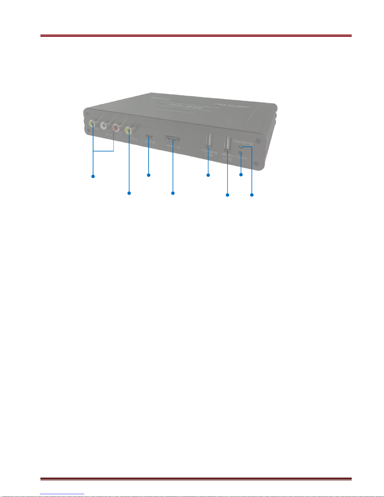
I.1 Front Side........................................................................................................................................... 5
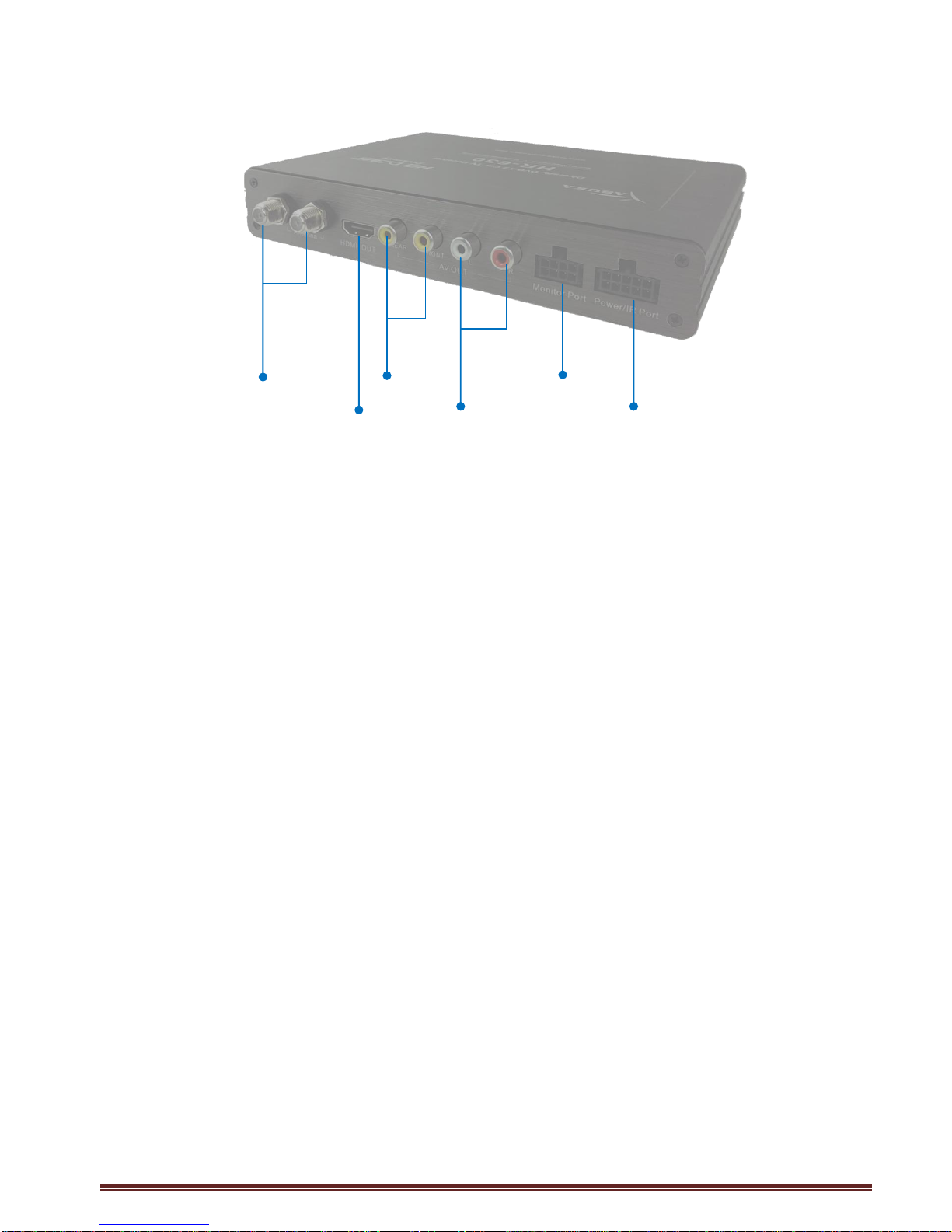
I.2 Rear Side............................................................................................................................................ 6
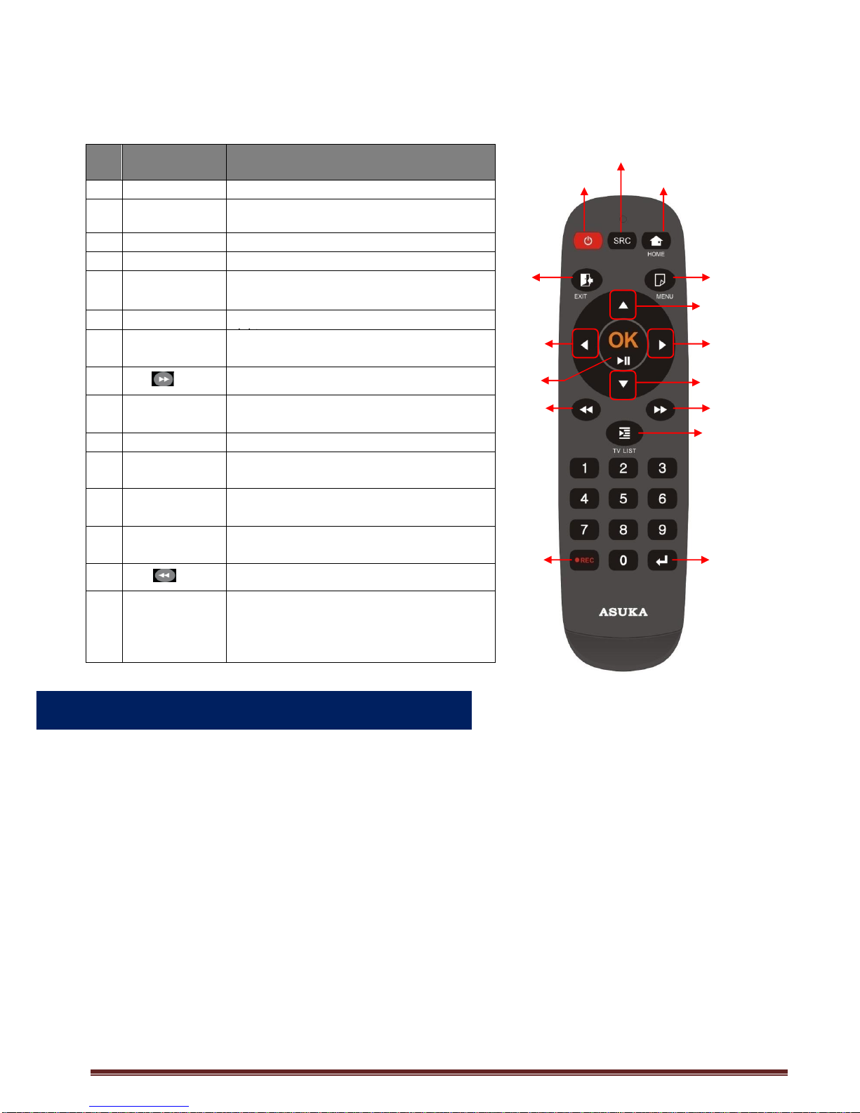
I.3 Remote Control Operations............................................................................................................. 7
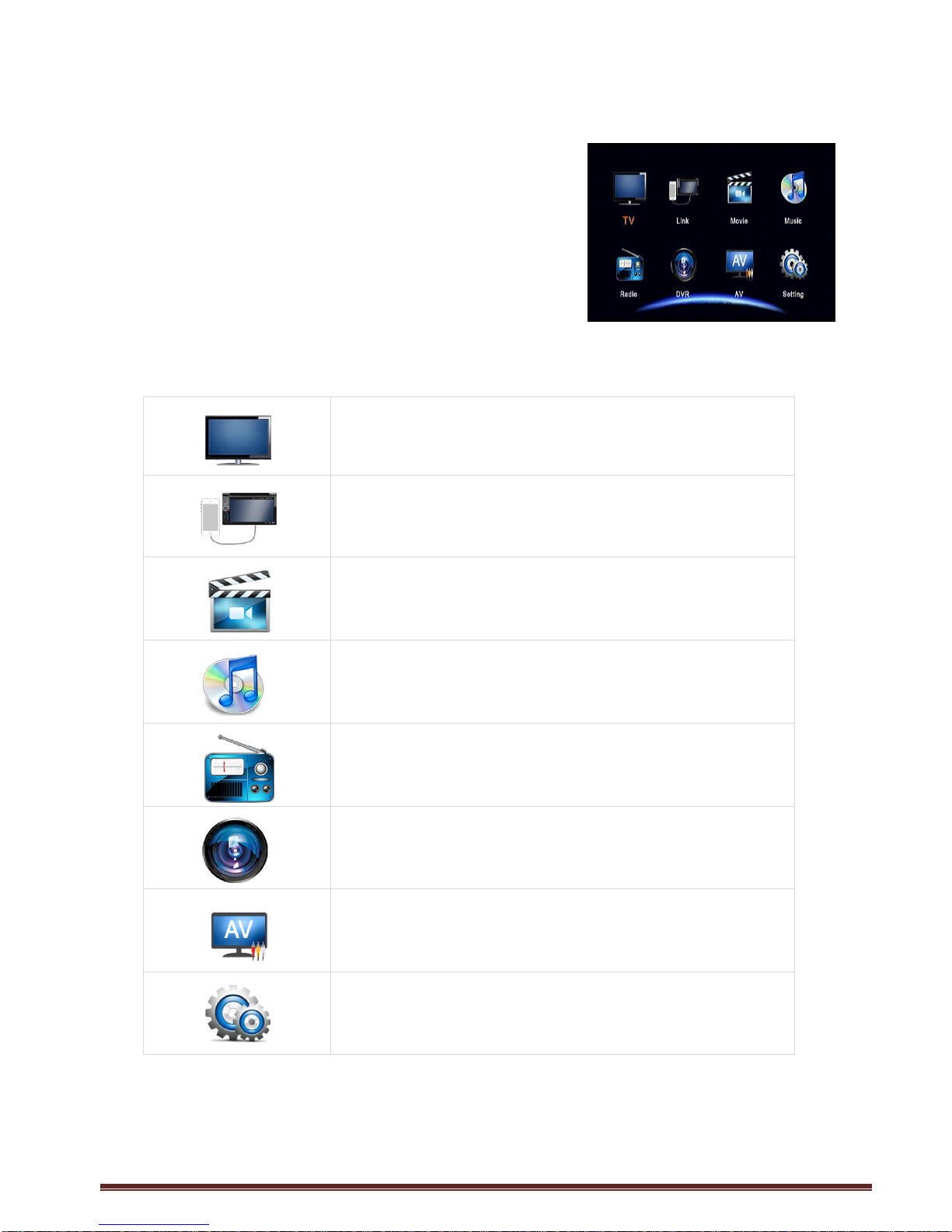
I.4 Home Menu........................................................................................................................................ 8
II. Installation & Configuration Guide.........................................................9
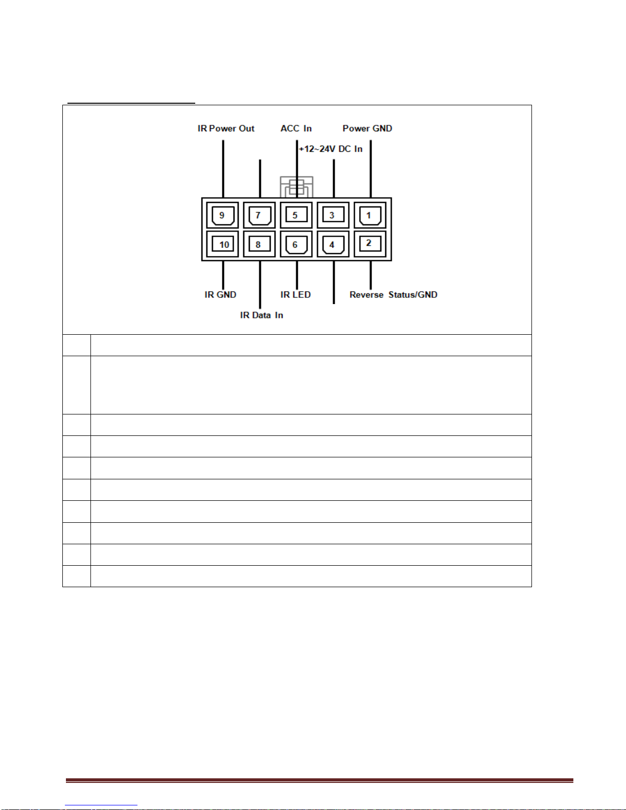
II.1 I/O Overview.................................................................................................................................... 10
II.2 Antenna Connection....................................................................................................................... 12
II.3 Smart phone Connectivity............................................................................................................. 14
II.4 Operating HR-630 from Steering Wheel Control(SWC)........................................................... 16
II.5 Touch control with Tier-1 Head Units .......................................................................................... 20
II.6 When having multiple external AV devices ................................................................................ 23
III. Quick Guide for First-time User...........................................................24
III.1 TV Watching................................................................................................................................... 24
III.2 TV Recording................................................................................................................................. 26
III.3 Smart phone connection.............................................................................................................. 27
III.4 MOVIE Watching........................................................................................................................... 28
III.5 MUSIC Listening............................................................................................................................ 29
IV. TV Mode ........................................................................................30
IV.1 TV Menu......................................................................................................................................... 30
IV.1.1 CH List (Channel List)..................................................................................................30
IV.1.2 Audio...............................................................................................................................31
IV.1.3 CH Info.(Channel Information)....................................................................................31
IV.1.4 Auto Search ...................................................................................................................32
IV.1.5 Channel Manager .........................................................................................................32
IV.1.6 Display............................................................................................................................33
IV.1.7 TV Setting.......................................................................................................................33
V. MOVIE Mode...................................................................................35
VI. MUSIC Mode...................................................................................36
VII. Radio Mode ....................................................................................37
VIII. System Setting................................................................................38
VIII.1 Country/Language.........................................................................................................38
VIII.2 Display.............................................................................................................................38
VIII.3 Monitor Port Setting.......................................................................................................38
VIII.4 Steering Wheel Control (SWC) Learning...................................................................39
VIII.5 HDMI Setting..................................................................................................................41
VIII.6 Antenna Power Setting.................................................................................................41
VIII.7 Version / Upgrade..........................................................................................................41
VIII.8 Reset Default..................................................................................................................41
IX. Trouble Shooting Q&A ......................................................................42
X. Specification...................................................................................44

ASUKA HR-630 User Manual 4
Product Introduction
ASUKA HR-630 is designed for users to access terrestrial DVB-T2 TV broadcasting services
recently emerging in many countries. With its state-of-the-art TV signal reception performance and
AV codec processing techniques, HR-630 promises to deliver users an easy access of local HD
DVB-T2 TV programs as well as enhanced HD media player functions over existing multimedia
features.
Besides, HR-630 provides unique features and capability to make it more fun and convenient for
in-car information & entertainment experience. They are:
1. Smart phone connectivity: It’s an easy & convenient to feed the smart phone contents into
the head-unit. Either iOS or Android mobile devices are supported.
2. Steering wheel control: For cars equipped with steering wheel control features, after a very
simple learning procedure, one can designate any 5 keys to perform the function of CH+, CH1,
ENTER, EXIT, and TV LIST respectfully. The use of steering wheel control keys for HR-630
operation control can significantly ease the operation complexity and make HR-630 extremely
suitable for in-car applications.
3. Providing both CVBS and RGB TV output: In addition to CVBS output, HR-630 also
provides optional RGB (progressive) TV output that is the expected video format by several
well-known head unit with the RGB TV output, HR-630 is capable of inter working with an even
wider range of head units in the market..

ASUKA HR-630 User Manual 5
I. Unit Overview
I.1 Front Side
(1) AV in : audio/video signal input port for external
devices connection such as DVD, GPS etc.
(2) CCD in : video input port for external CCD camera device connection
(3) DVR in : designated port for integration with ASUKA driving recorder.
(4) HDMI in : HDMI signal input port for mobile phone connection.
(5) Charging USB port : with DC +5V output for battery charging of mobile devices.
(6) USB port : for USB stick or external hard disk connection to perform
multimedia playback, TV recording, or software upgrade.
(7) Operating LED : the LED light to indicate whether the system is working or not
(8) Power LED : the LED light to indicate whether the power has been actively
supplied to the device or not.
1
3
5
7
4
6
8
2

ASUKA HR-630 User Manual 6
I.2 Rear Side
(9) Antenna in : antenna input port (NOTE: the unit provides +5V phantom
power through RF signal pin.)
(10) HDMI out : HDMI signal output port
(11) Video out : CVBS video output ports
(12) Audio out : Audio left/right sound output ports
(13) Monitor Port*1: with RGB output signal and UART/IR control interface for
advanced integration with 2-Din headunits
(14) Power/SWC/IR Port*2 : with 12V/24V, ACC & GND car power inputs, steering wheel
button signal inputs and IR control interface
*1, See chapter II.1 for more information
*2, See chapter II.2 for more information
9
10
11
12
13
14

ASUKA HR-630 User Manual 7
I.3 Remote Control Operations
No
Button name
Function
1
POWER
Select the power-on or stand-by
2
SRC
Select a video source from
DTV/AV1/CCD/DVR
3
HOME
Go to the home screen
4
MENU
Enter the setup menu
5
CH▲
Select the channel up or move the cursor
up
6
VOL
Select the volume up or move the cursor
right
7
CH▼
Select the volume up or move the cursor
right
8
FF
Fast Forward
9
TV LIST
TV Program List
10
ENTER
To enter the selected item
11
EXIT
Exit the current setup
12
VOL
Select the volume down or move the cursor
left
13
OK
Select the highlighted item or select
play/pause
14
FR
Fast Rewind
15
REC●
-Start to record the TV/Radio program or
exit the recording
- Subtitle key in the normal operation mode
If the battery power in the remote controller becomes low, please follow the steps below to replace
a new battery:
1. Slightly push the battery case from the down to the up and pull out the battery case from the
remote control.
2. Replace the original battery with the new one.
3. Insert back the battery and the case into the remote control.
-Remote Control Battery Installation
[1]
[2]
[3]
[4]
[5]
[6]
[7]
[8]
[9]
[10]
[11]
[12]
[14]
[13]
[15]

ASUKA HR-630 User Manual 8
I.4 Home Menu
This is the home menu screen. From here, you can access
repestively the TV mode, LINK mode for smart phone
connection, Movie mode for video playback, Music mode for
music playback mode, RADIO mode, DVR mode, AV mode
and Setting mode for system settings.
1. Use [VOL ] and [VOL ] buttons to highlight the desired
mode.
2. Press [OK] button to enter the desired mode.
TV Mode
To enter the DTV mode.
Smart phone Link Mode
To enter the link mode and operate the smartpone
connectivity.
Movie Playback Mode
To enter the playback mode and watch the movie files.
Music Playback Mode
To enter the audio playback mode and listen to the music.
Radio Playback Mode
To enter radio playback mode and listen to Radio
broadcasting.
DVR Mode
To enter the driving recorder mode and watch the real
time video.
AV Mode
To select the AV output sourcing.
System Settings
To configure the device settings.
Note: Press the [HOME] key to go back to the home screen anytime.
Press the [SOURCE] key to switch the AV source anytime.

ASUKA HR-630 User Manual 9
II. Installation & Configuration Guide
The HR-630 provides three different kinds of video output ports: AV OUT, HDMI, and Monitor Port
-Configuration overview
HR-630
Contents Sources
available at each
HR-630 output port
CONNECTED Car TV Diversity
Receiver
Smart phone link
AV 1/AV2
Driving Recorder
USB devices
Input devices
AV OUT
(CVBS signal)
Monitor Port
(RGB signal)
HDMI Port:
TV
USB
Smartphone
TV
USB
TV
USB
Smartphone
DVR
AV1/AV2

ASUKA HR-630 User Manual 10
II.1 I/O Overview
Power/SWC/IR Port
1
Ground (black wire). Connect this cable to the vehicles chassis ground.
2
- Reverse status (orange wire). Connect this cable to the reverse gear to see the
image of the rear view camera image on the front monitor.
- Keep the cable grounded if the reverse mode is not enabled.
3
+12 ~ 24 V DC input (yellow wire). Connect this cable to (+) pole of the battery
4
Steering In 2 (green wire). Plug in the cable to the SWC output wire 2.
5
ACC (red wire). Connect this cable to the ACC ignition of your vehicle.
6
IR (Infrared) LED power. Power for the LED of the IR receiver.
7
Steering In 1 (Blue wire). Plug in the cable to the SWC output wire 1.
8
IR (Infrared) data input. Infrared data of the IR receiver.
9
IR (Infrared) power. Power of the IR LED.
10
IR ground. Ground for the IR LED.
Steering In 1
Steering In 2

ASUKA HR-630 User Manual 11
Monitor Port
1
UART TX output
2
UART RX input
3
Csync output
4
Ground
5
RGB_B (Video output)
6
Ground
7
RGB_R (Video output)
8
RGB_G (Video output)
DVR Port
1
Ground
2
Reserved
3
CVBS video input
4
Audio input
5
IR data output
6
UART RX input
7
+12V ACC output
8
UART TX output
9
+12V battery output
10
Reserved
UART_RX
Ground
Ground
RGB_G
Mini USB
UART_T
X
Csync
RGB_B
RGB_R

ASUKA HR-630 User Manual 12
II.2 Antenna Connection
In-car digital TV reception situation will vary from vehicle to vehicle and the installer may need
to try anetnna mounting positions to determine the best position for most stable signal reception in
vehicles.
Important Notes on Antenna Installation:
For a better reception, please place the rod antenna horizontally, and keep the rod antenna away
from metals.
Antenna Position
To optimize the TV reception performance, we recommend that one antenna is mounted at the front
and one at the rear of the vehicle. Please refer to the diagram below for some recommended
locations.
(1) Behind the Front Bumper. Note: Please make sure the bumper is not made of metal
(2) Top of the Front Windscreen, but at least 5cm away from the metal body of the car
(3) Top of the Rear Windscreen, but at least 5cm away from the metal body of the car
(4) Bottom of the Rear Windscreen, at least 5cm away from the metal body of the car
(5) Behind the Rear Bumper (note: make sure rear bumper is not made of metal)
*Noted: For position (2) ~ (4), because the windshields of many cars are usually equipped with film coating
(that contains metal), the actual signal reception may be degraded, depending on the amount of the metal
embedded within the film.
1
2
3
4
5

ASUKA HR-630 User Manual 13
Antenna Cable Routing
Once a suitable position of antenna placement is found, carefully route the antenna cables to the
receiver unit and then connect to theAntenna Inputs on DTV receiver.

ASUKA HR-630 User Manual 14
II.3 Smart phone Connectivity
If you are like most people these days, you’ve made your smartphone the source for Youtube,
Google Map, and any other Internet information surfing.
To answer the increasing demand of Internet access within a car via smartphone, HR-630 provides
an efficient way to connect your smartphone to the head unit display on car monitor.
Connect your smart phone to the HDMI input port of HR-630. Different interconnection cable should
be used for iOS and Android devices, respectifully, as illustrated below:
iOS device : Lightning HDMI adaptor HDMI cable HDMI IN port of HR-630
device.
Android device: MHL cable HDMI IN port of HR-630 device.
-Configuration:

ASUKA HR-630 User Manual 15
After proper interconnection cable is well installed, please enter the home menu as shown below.
Select LINK mode and press [OK] button to execute smart phone connection.
If the connection is successfully activated, the mirroring image of smart phone will become also
available on car monitor as shown in the below:
-Set up the connection

ASUKA HR-630 User Manual 16
II.4 Operating HR-630 from Steering Wheel Control (SWC)
Most car models provide easy and convenient operation
control of in-car entertainment devices (ex. AM/FM
radio and/or media player) through the use of Steering
Wheel Control (SWC) buttons. Typical SWC buttons
offered originally, if any, are such as CH+, CH-, VOL+,
VOL-. To provide users further enhanced convenience,
HR-630 has been designed to support steering wheel
control buttons to allow users change the TV to
adjacent channel or any desired TV channels promptly. Operation is Quick and No hassle!
Here is a brief summary how HR-630 works to achieve this operational convenience.
(1) 5 major TV function keys from steering wheel control are supported in HR-630. They are: TV
LIST , Channel up(CH+), Channel down (CH-), ENTER, and EXIT.
Tell HR-630 Which is Which: First, users shall go to SETTING mode as explained in the
following paragraph to “teach”HR-630 which button on your steering wheel would be
assigned to which function. Note that the correspondence could be arbitrary. However, to
avoid unexpected results, the following SWC buttons shall NOT be used for these function
assignments: VOL+, VOL-, MOD.
(2) Use CH+/CH- button to change to adjacent TV channel.
(3) One may first pop up the entire TV List by pressing TV LIST button and then navigate to other
desired channel by using CH+ or CH- button.
Steering wheel
Control signals
2-Din head unit
Steering Wheel
ASUKA Car-TV Receiver
AV SIGNAL
2 ~ 3 wires,
15V max
(GND, output_1,
& output_2)
-Operation Overview
Note: The HR-630 can detect the SWC
output voltage level from 0.2V ~ 15V.

ASUKA HR-630 User Manual 17
The steering wheel control signals available from most car models are usually consisted of 2 or 3
wires. Generally speaking, when one press a particular SWC button, a specific voltage will be
presented at one and/or 2 wires to “inform ”the peripheral devices (ex. TV receiver) that a SWC
button has been asserted. The TV receiver can therefore interpret the voltage and perform the
corresponding action (CH+, CH-, ENTER, EXIT, TV LIST or nothing) in accordance with function
asserted.
The above-mentioned theories of operation are conceptually illustrated in the above wiring diagram.
1. The designated inputs of Power/IR port for SWC signals are Power GND (Black wire), Steering
In 1 (Blue wire), and Steering In 2 (Green wire).
2. Connection diagram is as follows:
SWC GND Power GND;
SWC output wire 1Steering In 1(Blue wire); and
SWC output wire 2 Steering in 2 (Green wire).
-System Configuration for SWC Control

ASUKA HR-630 User Manual 18
Since a car will have its own unique output voltage for each SWC button, a learning procedures to
make HR-630 becomes familiar with the specific SWC signal becomes necessary. This following
pictures will describe the steps required to achieve the SWC learning for 5 major TV function keys.
1. Start Steering Wheel Control Learning:
1.1 Back to Main Menu
1.2 Enter Setting Mode and select Steering Control
Learning
2. Learning Channel up (CH+) Key:
2.1 Select the “CH+ Key Learning”
2.2 Press the button of SWC designated for [CH+]
3. Learning Success
The “Success” message will pop up when HR-630
successfully gets the key of SWC.
4. Learning Channel Down (CH-) Key:
4.1 Select the “CH- Key Learning”
4.2 Press the button of SWC designated for [CH-]
5. Learning ENTER Key:
5.1 Select the “OK Key Lerning”
5.2 Press the button of SWC designated for [OK]
6. Learning EXIT Key:
6.1 Select the “EXIT Key Learning”
6.2 Press the button of SWC designated for [EXIT]
-How to set up SWC learning

ASUKA HR-630 User Manual 19
7. Learning TV LIST Key:
7.1 Select the “TV LIST Key Learning”
7.2 Press the button of SWC designated for [TV LIST]

ASUKA HR-630 User Manual 20
II.5 Touch control with Tier-1 Head Units
HR-630 provides advanced integration with tier-1 2-Din head units. This integration allow users to
operate HR-630 not only through remote controller but also through the touch screen and/or the
remote controller of the head unit. Below table is listed to summarize the head unit models that
HR-630 can support and the available methods to control TV functions after integration.
Supported Model
Available methods to control HR-630 after integration
SONY
Touch screen control,ASUKA remote control
Kenwood
Touch screen control, Kenwood remote control, ASUKA remote control
JVC
Touch screen control, JVC remote control, ASUKA remote control
To enable the function of touch control operation, a specific installation way for different headunit is
required. For instance, the different interconnection cable is requested for each specific headunit to
connect with HR-630. The installation guide for each supported head units is summarized as below
for reference.
Configuration :
Video connection : Plug the SONY interconnection cable to the Monitor port on HR-630, and
insert the other side to Navigation port on SONY head unit.
Audio Connection : Plug audio L/R RCA cable to AV L/R Out on HR-630 and insert the other side
to AUX IN on SONY head unit.
Audio L/R Output
SONY interconnection cable
-SONY Head Unit
Audio L/R RCA cable
Monitor port
Table of contents
Other Asuka Receiver manuals
Popular Receiver manuals by other brands

sewerin
sewerin AQUAPHON A 50 operating instructions

Onkyo
Onkyo TX-NR901 Service manual

CDVI
CDVI SEL2641R433-XPL operating instructions

Lee Technology
Lee Technology IQ-2008 Instructional manual

Onkyo
Onkyo TX-SR505 instruction manual

Agilent Technologies
Agilent Technologies MXE EMI Receiver N9038A Specifications guide