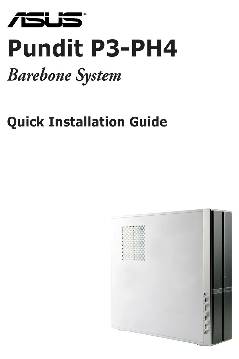
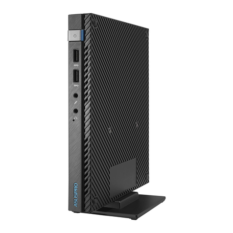
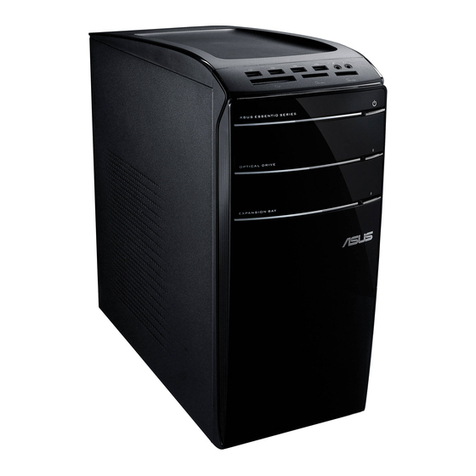
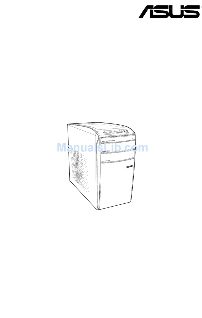
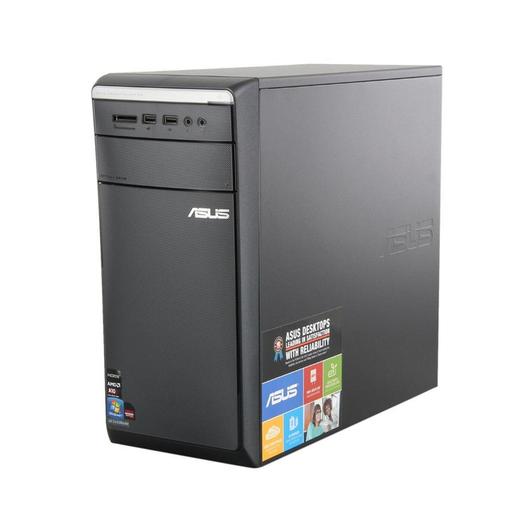
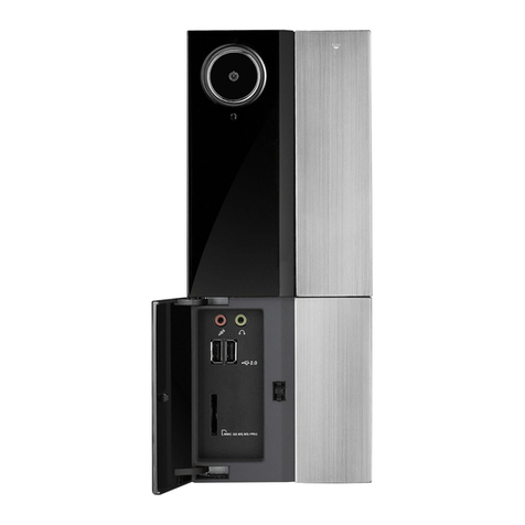
Asus P6 Series User manual

English
P6 Series
ASUS PC (Desktop Barebone)
Installation manual
A6359_P6 QSG.indb 1 2/16/11 5:43:02 PM

2Installation manual
English
Front panel features
1. Power button. Press this button to turn the system on.
2. Front panel cover. Push to open the front panel cover.
3. Optical disk drive cover. Push to eject the optical disk tray.
4. Microphone port. This Mic (pink) port connects a microphone.
5. Headphone port. This Line out (lime) port connects a headphone with a
stereo mini-plug.
6. USB 2.0 / USB 3.0 ports. These Universal Serial Bus 2.0 / These UniversalThese Universal
Serial Bus 3.0 (USB 2.0 / USB 3.0) ports are available for connecting USB(USB 2.0 / USB 3.0) ports are available for connecting USB
2.0 / USB 3.0 devices such as a mouse, printer, scanner, camera, PDA, and
others.
7. Multimedia Card / Secure Digital™ / MemoryStick®/ Memory Stick Pro™
card slot
1
2
3 1
4
3
5
6
7
A6359_P6 QSG.indb 2 2/16/11 5:43:04 PM

3
Installation manual
English
4. Power connector.
5. One of the following audio ports congurations:
• 6-channel
• 8-channel
Refer to the conguration table in the User Guide
for details.
6. LAN (RJ-45) port ( )
7. USB 2.0 / USB 3.0 ports ( )
8. VGA port ( )
9. One of the following ports:
• E-SATA port ( )
• Serial (COM1) port ( )
• DVI port ( )
• HDMI port ( )
Do NOT cover the rear vent , and the ambient
temperature is limited up to 35oC to prevent the
system from overheating.
Rear panel features
1
2
3
1. Chassis air vent.
2. Power supply unit fan vent.
3. Chassis fan vent.
4
5
9
A6359_P6 QSG.indb 3 2/16/11 5:43:10 PM

4Installation manual
English
Internal components
1. Front panel cover
2. 5.25-inch optical drive bays
3. Hard disk drive bay
4. Power supply unit (under the HDD bay)
5. ASUS motherboard*
6. Expansion slot metal brackets
7. Metal bracket lock
NOTE: *Refer to the system User Guide for motherboard details.
1
3
4
5
2
6
5
7
A6359_P6 QSG.indb 4 2/16/11 5:43:11 PM

5
Installation manual
English
Removing the side cover and
front panel assembly
1. Remove the cover screws on the rear panel.
2. Pull the side cover toward the rear panel until its hooks disengage from the
chassis tab holes. Set the side cover aside.
3. Locate the front panel assembly hooks, then lift them until they disengage
from the chassis.
4. Swing the front panel assembly to the left, until the hinge-like tabs on the
right side of the assembly are exposed.
5. Remove the front panel assembly, then set aside.
Air duct
1
1
2
4
3
4
4
3
3
3
Chassis tab holes
4
4
2
4
A6359_P6 QSG.indb 5 2/16/11 5:43:12 PM

6Installation manual
English
Installing a CPU
CAUTION! To prevent damage to
the socket pins, do not remove the
PnP cap unless you are installing
a CPU.
Installing an Intel®CPU in the LGA775 package
1. Locate the CPU socket on the motherboard.
2. Press the load lever with your thumb
(A), then move it to the left (B) until it
is released from the retention tab.
3. Lift the load lever in the direction of the arrow to
a 135º angle.
4. Lift the load plate with your thumb and
forenger to a 100º angle (4A), then push the
PnP cap from the load plate window to remove
(4B).
Gold
triangle
mark
Alignment key
Load lever
Retention tab
A
B
Load plate
PnP cap
4B 4A
B
A
5. Position the CPU over the socket, making
sure that the gold triangle is on the bottom-left
corner of the socket. Fit the socket alignment
key into the CPU notch.
6. Close the load plate (A), then push the load
lever (B) until it snaps into the retention tab.
3
A6359_P6 QSG.indb 6 2/16/11 5:43:14 PM

7
Installation manual
English
CAUTION! To prevent damage to the
socket pins, do not remove the PnP cap
unless you are installing a CPU.
Installing an Intel®CPU in the LGA1156 package
1. Locate the CPU socket on the motherboard.
2. Press the load lever with your thumb (A),
and then move it to the right (B) until it is
released from the retention tab.
A
B
Load lever
Retention tab
3. Lift the load lever in the direction of the arrow
until the load plate is completely lifted.
4. Remove the PnP cap from the CPU socket by
lifting the tab only.
Load plate
PnP cap
Cap tab
3
4
5. Position the CPU over the socket, ensuring that
the gold triangle is on the bottom-left corner of
the socket, and then t the socket alignment
keys into the CPU notches.
Gold
triangle
mark
Alignment keys
CPU notches
6. Close the load plate (A), and then push down
the load lever (B), ensuring that the front edge
of the load plate slides under the retention lock
(C).
C
B
A
A6359_P6 QSG.indb 7 2/16/11 5:43:16 PM

8Installation manual
English
Installing the CPU fan and heatsink assembly
Installing an Intel®CPU heatsink and fan
1. Place the heatsink on top of the installed
CPU, making sure that the four fasteners
match the holes on the motherboard.
2. Push down two fasteners at a time in a
diagonal sequence to secure the heatsink
and fan assembly in place.
3. When the fan and heatsink assembly is in
place, connect the CPU fan cable to the
connector on the motherboard.
Installing an AMD CPU
1. Locate the CPU socket, then lift the socket lever to a 90º angle.
2. Install the CPU to the socket, making sure that the CPU corner with the gold
triangle matches the socket corner with a small triangle.
3. Push down the socket lever to secure the CPU.
CAUTION: Incorrect installation of the CPU into the socket may bend the pins and
severely damage the CPU!
1 2 3
2
2
2
2
11
7. Insert the load lever under the retention tab.
3
A6359_P6 QSG.indb 8 2/16/11 5:43:19 PM

9
Installation manual
English
Installing an AMD CPU heatsink and fan
1. Place the heatsink on top of the installed CPU.
IMPORTANT. Make sure that the fan and heatsink assembly perfectly ts the retention
mechanism module base; otherwise you can not lock the retention bracket.
2. Attach one end of the retention bracket to the retention module base.
3. Attach the other end of the retention bracket (near the retention bracket lock)
to the retention module base until it clicks in place.
NOTE. Your boxed CPU should come with installation instructions for the CPU, fan/heatsink
assembly, and the retention mechanism. If the instructions in this section do not match the
CPU documentation, follow the latter.
4. Push down the retention bracket lock on the retention mechanism to secure
the fan and heatsink to the module retention module base.
5. Connect the CPU fan cable to the connector on the motherboard.
CAUTION: Do not forget to connect the CPU fan connector! Hardware monitoring error
can occur if you fail to plug this connector.
Retention module base
CPU heatsink
CPU fan
Retention
bracket lock
Retention bracket
CPU fan
connector
2
1
5
3
4
A6359_P6 QSG.indb 9 2/16/11 5:43:20 PM

10 Installation manual
English
Installing an expansion card
2. Remove the screw and then
remove the metal bracket lock.
1. Remove the metal cover opposite
the slot that you intend to use.
3. Insert the card connector to the slot,
then press the card rmly until it ts
in place.
4. Replace the metal bracket lock and
secure it with the screw.
Installing a DIMM
1. Locate the DIMM sockets in the motherboard.
2. Unlock a DIMM socket by pressing the retaining clips outward.
3. Align a DIMM on the socket such that the notch on the DIMM matches the
break on the socket.
4. Push the DIMM to the socket until the retaining clips snap inward.
CAUTION:
• Unplug the power supply before adding or removing DIMMs. Failure to do so may
cause damage to the motherboard and/or components.
• A DIMM is keyed with a notch so that it ts in only one direction.
Do not force a DIMM into a socket to avoid damaging the DIMM.
1
2
3
4
NOTE: In order not to interfere other expansion card’s installation, ensure that the
thickness of the heatsink and fan on the expansion card is less than 27 millimeters.
2
2
3
4
4
4
A6359_P6 QSG.indb 10 2/16/11 5:43:23 PM

11
Installation manual
English
Hard disk drive
1. Remove the two screws on the hard disk
drive holder.
2. Lift the hard disk drive holder upward.
3. Insert the hard disk drive to the hard disk
drive holder, then carefully push the drive
until its screw holes align with the holes on
the holder.
4. Secure the hard disk drive with four screws
on top of the holder.
5. Rotate the hard disk drive holder back to its
place and secure it to the chassis with the
two screws you removed earlier.
Installing storage drives
Optical drive
1. Remove the front panel assembly.
2. Insert the optical drive to the bay, then
carefully push the drive until its screw
holes align with the holes on the bay.
3. Secure the optical drive with four
screws at the bottom of the bay.
4. Connect the IDE (4A) and power (4B)
plugs to connectors at the back of the
drive. 4B
4A
3
2
1
2
6. For SATA HDD: Connect the SATA
signal and power plugs to the
connectors at the back of the drive
(6A).
For IDE HDD: Connect the IDE and
power plugs to the connectors at the
back of the drive (6B).
SATA IDE
3
4
5
6A 6B
44
4
A6359_P6 QSG.indb 11 2/16/11 5:43:26 PM

12 Installation manual
English
Reinstalling the front panel assembly and
side cover
To reinstall the front panel assembly and side cover:
1. Insert the front panel assembly hinge-like tabs to the holes on the left side of
the chassis.
2. Swing the front panel assembly to the right, then insert the hooks to the
chassis until the front panel assembly ts in place.
3. Insert the six side cover hooks into the chassis tab holes .
4. Push the side cover to the direction of the front panel until it ts in place.
5. Secure the cover with two screws you removed earlier.
Air duct
5
5
3
4
1
2
1
1
2
2
2
Chassis tab holes
1
2
1
A6359_P6 QSG.indb 12 2/16/11 5:43:28 PM

日
本
語
P6 Series
ASUS PC (デスクトップ ベアボーン)
ユーザーマニュアル
A6359_P6 QSG.indb 13 2/16/11 5:43:31 PM

14 ユーザーマニュアル
日
本
語
日
本
語
日
本
語
日
本
語
フロントパネル
1. 電源ボタン システムの電源をONにします。
2. フロントパネルカバー を押し、フロントパネルカーバーを開けます。
3. 光学ディスクドライブカバー を押し、光学ディスクドライブをイジェクトします。
4. マイクポート このピンクのポートはマイクを接続します。
5. ヘッドホンポート このライムの配線ポートはステレオミニプラグ付きのヘッドホ
ンを接続します。
6. USB3.0/2.0ポート これらのUSB3.0/2.0ポートは、マウス、プリンター、スキャナ
ー、PDA、などその他のUSB3.0/2.0デバイスを接続することが
できます。
7. カードリーダー MMC/SDカード/メモリースティック
1
2
3 1
4
3
5
6
7
A6359_P6 QSG.indb 14 2/16/11 5:43:33 PM

15
ユーザーマニュアル
日
本
語
日
本
語
日
本
語
日
本
語
4. 電源コネクター
5. 以下のオーディオポート設定のうちどれかひとつ
• 6チャンネル
• 8チャンネル
詳細につきましては、ユーザーマニュアルの設定表をご参
照ください。
6. LAN(RJ-45)ポート( )
7. USB3.0/2.0ポート( )
8. VGAポート( )
9. 以下のポートのどれかになっています。
• E-SATAポート( )
• Serial(COM1)ポート( )
• DVIポート( )
• HDMIポート( )
バックパネルの通気孔を絶対に塞がないで下さい。周辺温
度の制限は、システムのオーバーヒートを避けるため最高
35oCになっています。
バックパネル機能
1
2
3
1. ケース通気孔
2. 電源供給ユニットファン通気孔
3. ケースファン通気孔 4
5
9
ヒント: 各ポートの配置等はモデルによって異なります。
A6359_P6 QSG.indb 15 2/16/11 5:43:38 PM

16 ユーザーマニュアル
日
本
語
日
本
語
日
本
語
日
本
語
内部コンポーネント
1. フロントパネルカバー
2. 5.25インチ光学ドライブベイ
3. ハードディスクドライブベイ
4. 電源ユニット(HDDベイの下)
5. ASUSマザーボード*
6. 拡張スロットメタルブラケット
7. メタルブラケットロック
注意:*マザーボードの詳細につきましては、ユーザーマニュアルをご参照ください。
1
3
4
5
2
6
5
7
A6359_P6 QSG.indb 16 2/16/11 5:43:39 PM

17
ユーザーマニュアル
日
本
語
日
本
語
日
本
語
日
本
語
サイドカバーとフロントパネルの取り外し
1. バックパネルのネジを外します。
2. サイドカバーをバックパネルの方へ、ケースの穴から留め具が外れるまでスライドし、サイ
ドカバーを取り外します。
3. フロントパネルの留め具を、ケースから外れるまで持ち上げます。
4. フロントパネルを、ヒンジのようなタブが見えるまで右へ移動させます。
5. フロントパネルを取り外します。
通気孔
1
1
2
4
3
4
4
3
3
3
ケースの穴
4
4
2
4
A6359_P6 QSG.indb 17 2/16/11 5:43:41 PM

18 ユーザーマニュアル
日
本
語
日
本
語
日
本
語
日
本
語
CPUを取り付ける
注意: ソケットピンの損傷防止のため、ソ
ケットキャップはCPUを取り付ける
まで外さないでください。
Intel® CPUを LGA775 に取り付ける
1. マザーボードのCPUソケットの位置を確認
します。
2. 親指でロードレバーを押し(A)、タブから外
れるまで外側に動かします(B)。
3. ロードレバーを矢印の方向(135ºの角度)へ持ち上げま
す。
4. ロードプレートを、親指と人差し指で100ºの方向へ持ち
上げ、ロードプレートウィンドウにあるソケットキャップ
押し、取り外します。(4B)
ロードレバー
タブ
A
B
ロードプレート
ソケット
キャップ
4B 4A
B
A
5. CPUに書かれている金色の三角形がソケットの左下隅に
なるようにCPUをソケットの上に載せます。このとき、ソ
ケットの位置合わせキーは、CPUの溝にぴったり合わせ
る必要があります。
6. ロードプレート(A)を閉じ、ロードレバー(B)がタブにき
っちりはまるまで押し入れます。
3
金色の
三角形
位置合わせキー
A6359_P6 QSG.indb 18 2/16/11 5:43:43 PM

19
ユーザーマニュアル
日
本
語
日
本
語
日
本
語
日
本
語
注意: ソケットピンの損傷防止のため、ソケット
キャップはCPUを取り付けるまで外さない
でください。
Intel® CPUを LGA1156 に取り付ける
1. マザーボードのCPUソケットの位置を確認します。
2. 親指でロードレバーを押し(A)、タブから外れる
まで外側に動かします(B)。
A
B
ロードレバー
タブ
3. 矢印の方向にロードプレートを完全に持ち上げます。
4. タブだけを上に上げ、CPUソケットからソケットキャップ
を取り外します。
ロード
レバー
ソケット
キャップ
キャップタブ
3
4
5. CPUに書かれている金色の三角形がソケットの左下隅に
なるようにCPUをソケットの上に載せます。このとき、ソケ
ットの位置合わせキーは、CPUの溝にぴったり合わせる
必要があります。
金色の
三角形の
マーク
位置合わせキー
CPUノッチ
6. ロードプレート(A)を閉じ、ロードレバー(B)を押し下ロードプレート(A)を閉じ、ロードレバー(B)を押し下
げ、ロードプレートがノブ(C)に収まるよう、所定の位置
まで戻します。
C
B
A
A6359_P6 QSG.indb 19 2/16/11 5:43:44 PM

20 ユーザーマニュアル
日
本
語
日
本
語
日
本
語
日
本
語
CPUにヒートシンクとファンを取り付ける
Intel® CPUヒートシンクとファンを取り付ける
1. 4つのファスナーがマザーボードの穴の位置と合って
いることを確認しながら、ヒートシンクをCPUの上に
置きます。
2. 対角線上にある2つのファスナーを同時に押し下げ、
ヒートシンクとファンを正しい場所に固定します。
3. ファンとヒートシンクを取り付けた時、CPUファン
ケーブルをマザーボードのコネクターに接続します。
AMD CPUを取り付ける
1. CPUソケットのレバーを90ºに持ち上げます。
2. CPUに書かれている金色の三角形がソケットの左下隅になるようにCPUをソケットの上に載せま
す。このとき、ソケットの位置合わせキーは、CPUの溝にぴったり合わせる必要があります。
3. CPUがしっかりとはまるよう、ソケットレバーを押し下げます。
注意: CPUは一方向にのみぴったり合うようになっています。CPUをソケットに無理に押し込まないでく
ださい。ソケットのコネクタが曲がる、あるいはCPUが破損する等の原因となります。
1 2 3
2
2
2
2
11
7. ロードレバーがタブに収まるまで押し入れます。
3
A6359_P6 QSG.indb 20 2/16/11 5:43:48 PM
Table of contents
Languages:
Other Asus Desktop manuals

Asus
Asus AAEON BOXER-8223AI User manual

Asus
Asus Vivo AiO V220 Series User manual

Asus
Asus D830MT User manual

Asus
Asus Essentio CM6340 User manual

Asus
Asus BM6AD User manual

Asus
Asus ZN242IF User manual

Asus
Asus P6-P7H55E User manual
Asus
Asus BM1AD1 User manual

Asus
Asus PE400D Series User manual

Asus
Asus BM1645/MD250 User manual

Asus
Asus V241 Series User manual

Asus
Asus PN80 User manual

Asus
Asus ESC300 G4 User manual

Asus
Asus Vintage V2-PE2 User manual

Asus
Asus V241F User manual

Asus
Asus PN41-S1 User manual

Asus
Asus T3-M2NC51PV - T Series - 0 MB RAM User manual

Asus
Asus GT51CA User manual

Asus
Asus BM6620 User manual

Asus
Asus AS-D777 User manual