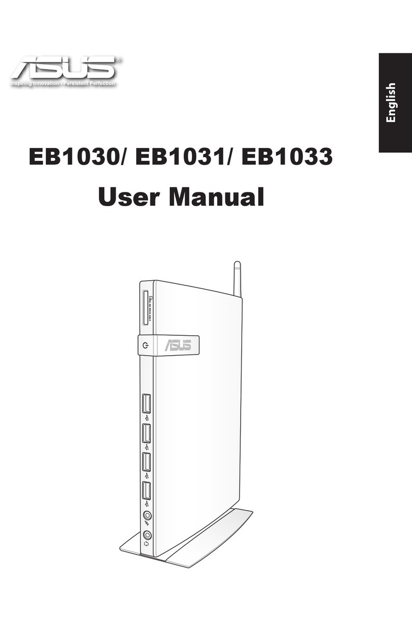
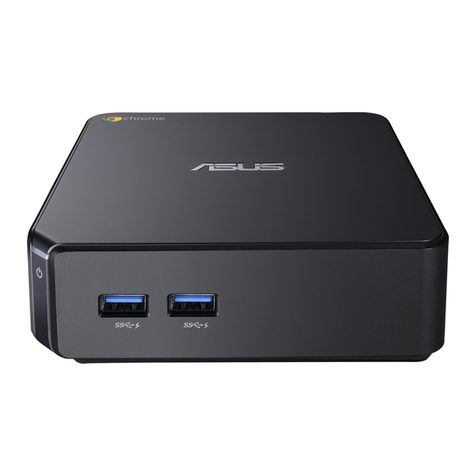
Asus VivoMini User manual

1
CA9955 Revised Edition V2
December 2014
VivoMini memory, wireless card, and
solid state drive (SSD) installation guide
Your VivoMini comes with two SO-DIMM memory slots that allow you to install two 2GB, 4GB, or
8GB unbuered with non-ECC 1.35 V DDR3 204-pin SO-DIMMs for a maximum of 16GB memory.
IMPORTANT! Refer to http://www.asus.com for the list of compatible DIMMs. You can only
install 1.35 V DDR3 SO-DIMM to the VivoMini’s DIMM slots.
IMPORTANT!
• Itisrecommendedthatyouinstallorupgradethememorymodules,wirelesscard,and
solid state drive (SSD), under professional supervision. Visit an ASUS service center for
further assistance.
• Ensurethatyourhandsaredrybeforeproceedingwiththerestoftheinstallation
process.Beforeinstallinganyofthefeaturesinthisguide,useagroundedwriststrapor
touchasafelygroundedobjectormetalobjecttoavoiddamagingthemduetostatic
electricity.
Installing or upgrading memory modules
To install or upgrade the memory modules:
1. Turn o your VivoMini then disconnect all cables and peripherals.
2. PlacetheVivoMinionaatstablesurface,withitstopsidefacingdown.
YourVivoMinicomeswiththefollowingitems.PleasecontactASUSServiceCenterifyoucannot
ndthefollowingitems:
• 4pcsholedrubberfoot
• 3pcs3mmroundscrews,1hexagonscrew
15060-4790R100

2
4. Get one screw from the ones you previously removed then place it into the hole. Leave
aportionofthescrewheadthatwouldbeenoughforyoutohold.
3. Removethefourscrewssecuringthecover.
5. HoldthescrewthengentlypulloutthecoverfromthebottomsideoftheVivoMini.Use
your other free hand to hold the VivoMini in place.

3
6. Alignandinsertthememorymoduleintotheslot(A)andpressitdown(B)untilitis
securely seated in place. Repeat the same steps to install the other memory module.
IMPORTANT! Always install into the lower slot rst.
7. Remove the screw you previously attached on the bottom cover.
8. Place the cover back on the bottom side of your VivoMini. Note that the cover can only
beinsertedinonedirection.Refertothefollowingillustrationandnotetoensurethat
the cover is securely tted on the bottom side of the VivoMini.
IMPORTANT!Therating
label area (A) and the
power button’s location
(B) must be oriented as
shown.

4
10. Place the rubber foot on each screw hole. Refer to the illustration for more details.
IMPORTANT! A number is printed under each rubber foot and this number corresponds
to that rubber foot’s location on the cover. Follow the orientation of each rubber foot
and the number sequence shown in the illustration below. The rubber foot ts in only
one orientation. Note the position of the hole on each rubber foot, as shown in the
illustration below
NOTE: If you want to remove the rubber foot, use a athead screwdriver or a
straightenedpapercliptodoso.
9. Reattach the screws to secure the cover back on the bottom side of the main box.

5
Installing or upgrading the wireless card
To install or upgrade the wireless card:
1. Followsteps1-5onpages1-2undertheInstalling or upgrading memory modules section
ofthisguide to remove the bottom cover of your VivoMini.
2. AlignandinsertthewirelesscardintothelowerslotinsidetheVivoMini.Refertothe
illustration for its location.
3. Gentlypushdownthewirelesscardontopofthescrewholesandfastenitusingtwoof
the 3mm round screws.
Your VivoMini includes a mini-PCIe slot for half-size wireless and Bluetooth adapters.
Refer to http://www.asus.com for the list of compatible wireless and Bluetooth adapters.

6
Installing or upgrading the mSATA SSD
To install or upgrade a full-size mSATA SSD:
1. Followsteps1-5onpages1-2undertheInstalling or upgrading memory modules section
ofthisguide to remove the bottom cover of your VivoMini.
5. Followsteps7-9onpages3-4undertheInstalling or upgrading memory modules section
ofthisguidetoreplacethebottomcoverbackonyourVivoMini.
Your VivoMini includes a PCIe slot that supports a full-size or a half-size mSATA SSD.
4. Connect the black antenna to MAIN or and the white antenna to AUX or .Refer
totheillustrationfortherightinstallationprocedure.
NOTE:Asoftclickingsoundindicatesthattheantennahasbeensecurelyattachedon
the wireless card.

7
3. GentlypushdownthemSATASSDontopofthescrewholeandfastenitusingoneof
the 3mm round screw. Refer to the illustration for the location of the screw hole.
4. Followsteps7-9onpages3-4undertheInstalling or upgrading memory modules
sectionofthisguidetoreplacethebottomcoverbackonyourVivoMini.
2. Alignandinsertthefull-sizemSATASSDintoitstheupperslotinsidetheVivoMini.Refer
to the illustration for its location.
To install or upgrade a half-size mSATA SSD:
1. Followsteps1-5onpages1-2undertheInstalling or upgrading memory modules section
ofthisguide to remove the bottom cover of your VivoMini.

8
2. Insertthehexagonscrewintoitscorrespondinghole,asillustrated.
4. GentlypushdownthemSATASSDontopofthescrewholeandfastenitusingoneof
the 3mm round screw. Refer to the illustration for the location of the screw hole.
5. Followsteps7-9onpages3-4undertheInstalling or upgrading memory modules section
ofthisguidetoreplacethebottomcoverbackonyourVivoMini.
3. Alignandinsertthehalf-sizemSATASSDintoitsupperslotinsidetheVivoMini.Referto
the illustration for its location.

9
Guide d’installation de modules
mémoire, d’adaptateur sans l et de
lecteur SSD pour VivoMini
Votre VivoMini est doté de deux interfaces de connexion SO-DIMM (204 broches ; 1,35V) dédiées
à l’installation de modules mémoire DDR3 de 2 Go, 4 Go ou 8 Go, pour un maximum de 16 Go
de mémoire vive.
IMPORTANT ! Rendez-vous sur le site http://www.asus.com pour obtenir la liste des modules
mémoire compatibles.
IMPORTANT !
• Achetez et faites installer des modules mémoire, un adaptateur sans l et/ou un
lecteurSSDuniquementauprèsd’unrevendeuragréépourassureruneabilitéet
unecompatibilitéoptimale.Renseignez-vousauprèsd’uncentreagréépourplus
d’informations.
• Assurez-vous que vos mains sont sèches avant de procéder à l’installation de
composants additionnels. Avant de procéder à l’installation, utilisez un bracelet
antistatiqueoutouchezunobjetmétalliqueoureliéàlaterrepouréviterd’endommager
les modules mémoire.
Installer des modules mémoire
Pour installer ou mettre à niveau les modules mémoire :
1. ÉteignezvotreVivoMinietdéconnecteztouslescâblesetlespériphériques.
2. PlacezlafacesupérieureduVivoMinisurunesurfaceégaleetstable.
Votre ordinateur VivoMini est livré avec les éléments suivants. Contactez le service client ASUS si
l’undesélémentsestmanquantouendommagé.
• 4patinsencaoutchouc
• 3visrondesde3mm,1vishexagonale

10
4. Utilisez l’une des vis précédente et placez-la dans l’ouverture. Conservez une portion
susante de la tête de vis en dehors du couvercle d’ordinateur de sorte à pouvoir la
prendre en main.
3. Retirez les quatre vis sécurisant le couvercle.
5. Tirezd’unemainsurlavispourdésengagerlecouvercle.Utilisezvotreautremainpour
maintenir le VivoMini en place.

11
6. Alignezetinsérezlemodulemémoiredansleslot(A)etappuyezdessus(B)jusqu’àce
qu’il soit bien en place. Répétez les mêmes étapes pour installer un module mémoire
additionnel.
IMPORTANT ! Utilisez le slot inférieur en priorité.
7. Retirez la vis attachée au couvercle.
8. Replacez le couvercle en place. Le couvercle ne peut être inséré que dans un seul sens.
Consultez l’illustration ci-dessous pour vous assurer que le couvercle est bien placé sur
le boîtier du VivoMini.
IMPORTANT ! L’étiquette
listant les tensions (A)
ainsi que le bouton
d’alimentation (B) doivent
être orientés tel qu’illustré
ci-contre.

12
10. Placez les patins en caoutchouc. Reportez-vous à l’illustration pour plus de détails.
IMPORTANT ! Faites attention à l’orientation de chacun des patins en caoutchouc ainsi
que du chire imprimé sous chacun d’entre eux. Ces derniers indiquent la séquence de
retrait à suivre. Consultez l’illustration suivante pour plus de détails.
REMARQUE : Utilisez un tournevis à tête plate ou un trombone déplié pour
retirer les patins en caoutchouc du dessous de l’ordinateur.
9. Replacez les vis pour sécuriser le couvercle au boîtier principal.

13
Installer une carte sans l
Pour installer ou mettre à niveau un adaptateur sans l :
1. Suivezlesinstructions1à5despages1-2delasectionInstaller des modules mémoires
deceguidepourretirerlecouvercledevotreVivoMini.
2. Alignezetinsérezl’adaptateursansldansleslotinférieurduVivoMini.Reportez-vous
à l’illustration ci-dessous pour localiser son emplacement.
3. Alignezlespasdevisdel’adaptateursanslavecceuxdel’emplacementdédiéà
son installation à l’intérieur du VivoMini, puis sécurisez le tout à l’aide de deux des vis
rondes de 3mm incluses.
VotreVivoMiniintègreunslotmini-PCIedédiéauxadaptateursWi-FiouBluetoothàdemi-
hauteur.
Rendez-vous sur le site http://www.asus.compourconsulterlalistedesadaptateursWi-Fiet
Bluetooth compatibles.

14
Installer un lecteur SSD au format mSATA
Pour installer ou mettre à niveau un lecteur SSD mSATA de pleine hauteur :
1. Suivezlesinstructions1à5despages1-2delasectionInstaller des modules mémoires
deceguidepourretirerlecouvercledevotreVivoMini.
5. Suivezlesinstructionsdesétapes7à9despages3-4delasectionInstaller des modules
mémoire deceguidepourréinstallerlecouvercledevotreVivoMini.
VotreVivoMiniintègreunslotPCIepermettantl’installationd’unlecteurSSDmSATAdedemiou
pleine hauteur.
4. Connectez l’antenne noire sur la prise MAIN ou et l’antenne blanche sur la prise
AUX ou .Pour plus de détails, référez-vous à l’illustration ci-dessous.
REMARQUE :Unlégerclicretentitpourindiquerquel’antenneestcorrectement
connectée à l’adaptateur sans l.

15
3. AlignezlespasdevisdulecteurSSDmSATAavecceuxdel’emplacementdédiéàson
installation à l’intérieur du VivoMini, puis sécurisez le tout à l’aide d’une des vis rondes
de 3mm incluses.
4. Suivezlesinstructionsdesétapes7à9despages3-4delasectionInstaller des modules
mémoire deceguidepourréinstallerlecouvercledevotreVivoMini.
2. AlignezetinsérezlelecteurSSDmSATAsansldansleslotsupérieurduVivoMini.
Reportez-vous à l’illustration ci-dessous pour localiser son emplacement.
Pour installer ou mettre à niveau un lecteur SSD mSATA de demi-hauteur :
1. Suivezlesinstructions1à5despages1-2delasectionInstaller des modules mémoires
deceguidepourretirerlecouvercledevotreVivoMini.

16
2. Insérezlavishexagonaledansl'emplacementdédiéàceteetettelqu'illustréci-
dessous.
4. AlignezlespasdevisdulecteurSSDmSATAavecceuxdel’emplacementdédiéàson
installation à l’intérieur du VivoMini, puis sécurisez le tout à l’aide d’une des vis rondes
de 3mm incluses.
5. Suivezlesinstructionsdesétapes7à9despages3-4delasectionInstaller des modules
mémoire deceguidepourréinstallerlecouvercledevotreVivoMini.
3. AlignezetinsérezlelecteurSSDmSATAsansldansleslotsupérieurduVivoMini.
Reportez-vous à l’illustration ci-dessous pour localiser son emplacement.
Table of contents
Languages:
Other Asus Desktop manuals

Asus
Asus Essentio CM6870 User manual

Asus
Asus EB1037 User manual

Asus
Asus CT5430 User manual

Asus
Asus ExpertCenter D5 Tower User manual

Asus
Asus T3-P5G965 - T Series - 0 MB RAM User manual

Asus
Asus BM6330 User manual

Asus
Asus BM6875 User manual

Asus
Asus VivoPC Barebone User manual

Asus
Asus BP1AD User manual

Asus
Asus A4110-BD047D User manual

Asus
Asus Vivo AiO V220 Series User manual

Asus
Asus T3-M3N8200 User manual

Asus
Asus BT1AG User manual

Asus
Asus ET2410IUTS User manual

Asus
Asus V241F User manual

Asus
Asus G35CZ User manual

Asus
Asus Essentio CM1730 User manual

Asus
Asus P2-M3A3200 User manual

Asus
Asus PB60G User manual

Asus
Asus ESC2000 User manual