CUW-AM User’s Manual 1
1. FEATURES
Specifications
1. FEATURES
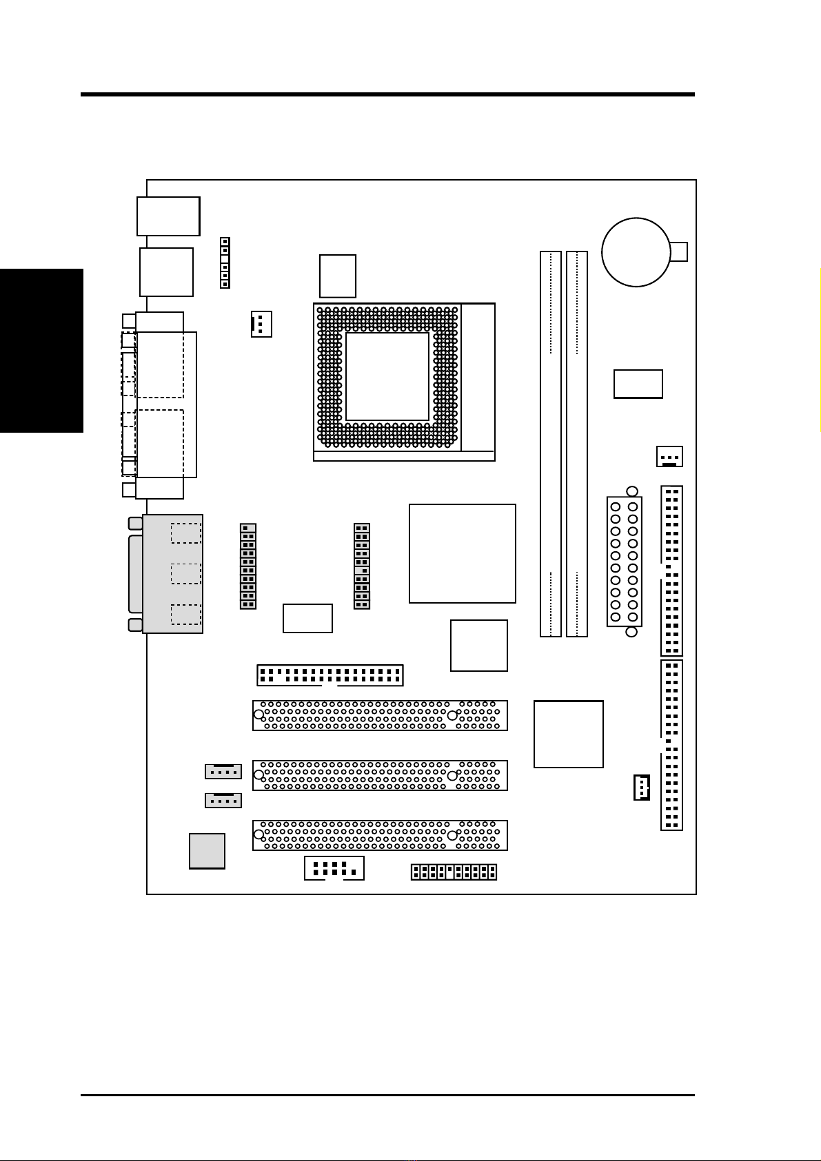
1.1 The CUW-AM
The CUW-AM motherboard is carefully designed for the demanding PC user who
wants advanced features processed by the fastest processors.
1.1.1 Specifications
•Latest Intel Socket 370 Processor Support
Intel Pentium
®
III 100MHz FSB Coppermine core FC-PGA
Intel Celeron™ 66MHz FSB Mendocino core PPGA
•Latest Intel 810 Chipset! The 810 (GMCH+ICH) supports 66/100MHz FSB
and UltraDMA/66.
•IntegratedGraphics!Controller supports 3D hyper pipelined architecture, par-
allel data processing and compression, precise pixel interpolation, full 2D hard-
ware acceleration, and motion video acceleration.
•Custom Graphics Driver! You can gain about 12% performance over that of
the standard graphics driver (2D highend graphics WinMark) using the custom
graphics driver. The custom graphics driver also provides more features and
provides selection of higher refresh rates and resolutions.
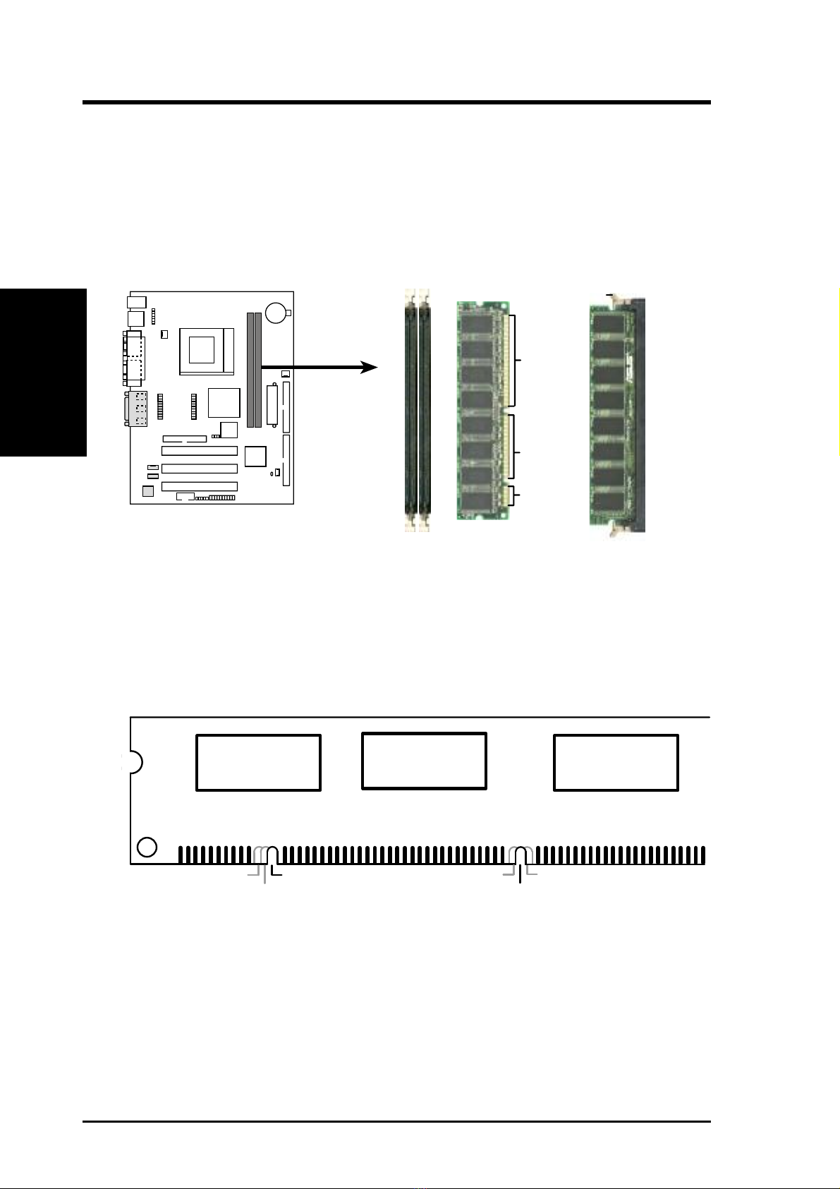
•Versatile Memory Support! DRAM controller supports asymmetrical address-
ing and two DIMM sockets support Intel PC100-compliant SDRAMs (16, 32,
64, 128, or 256MB) up to 512MB. (supports a maximum of 4 sides)
• Latest Low Pin Count Multi-I/O: Provides two high-speed UART compatible
serial ports and one parallel port with EPP and ECP capabilities.
• Integrated IDE! Controller supports UltraDMA/66 up to 66MB/s, UltraDMA/
33 up to 33MB/s, and PIO Mode 4 up to 17MB/s.
•Firmware Hub! Provides security and other latest power computing features.
•Enhanced ACPI & Anti-Boot Virus Protection! Programmable BIOS (Flash
EEPROM),offering enhancedACPIforWindows98compatibility,built-infirm-
ware-based virus protection, and autodetection of most devices for virtually au-
tomatic setup.
•Highest Audio Quality! AC’97 DAC/ADC (software audio) built into the au-
dio codec reduces noise to improve audio quality and performance for a SNR
(signal to noise ratio) of +90dB. These features greatly improve voice synthesis
and recognition. If more quality is required, an optional onboard Crystal PCI
audio improves audio quality beyond software audio.
E546