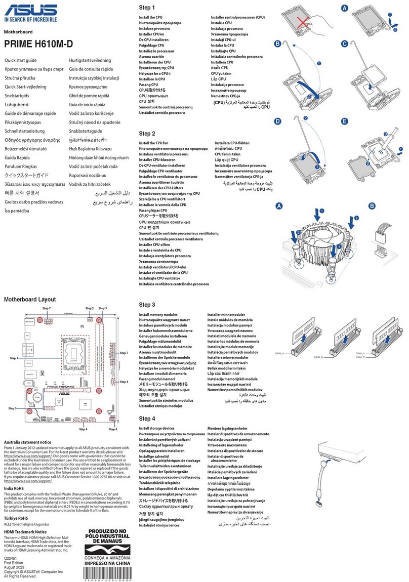
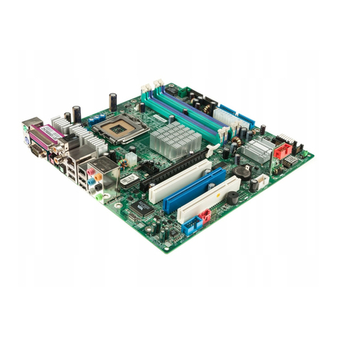
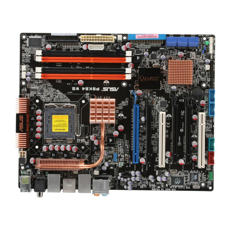
Asus GRYPHON ARMOR KIT User manual

Q8211
Contents
English .......................................................................................... 2
繁體中文 ......................................................................................... 7
....................................................................................... 12
日本語........................................................................................... 17

2
English
Package contents
Check your GRYPHON ARMOR KIT package for the following items:
Thermal Armor
TUF Fortier
1 x Back I/O port cap set
(LAN cap, HDMI cap, DVI cap,
DP cap, Front USB 3.0 cap)
9 x SATA/eSATA connector caps
10 x Onboard USB 2.0 connector caps
6 x Audio port caps
2 x DIMM slot covers
3 x PCIe x16 slot covers
1 x PCIe x1 slot cover
1 x bag of screws
1 x 40mm I/O cover fan lid
3
M
1 x Adhesive foam for 35mm fan
Thermal Armor and TUF
Fortier
Dust Grid Dust Frame
Back I/O Dust Filter TUF Connector Dust
Defender package
Back I/O Assistant fan
(35mm)
3 x Thermistor cables TUF Accessory package
Phillips screwdriver Installation Guide
• If any of the above items is damaged or missing, contact your retailer.
• To support various models, your TUF Connector Dust Defender package may include
additional onboard connector caps and back I/O port caps.
• The illustrated items above are for reference only.

3
English
Assembling the Thermal Armor and the TUF Fortier with your MB
To assemble your motherboard with the Thermal Armor and TUF Fortier:
3. Position your motherboard upside down to an
orientation that aligns its THE ULTIMATE FORCE logo
with the printed THE ULTIMATE FORCE logo on the
Thermal Armor.
4. Carefully put your motherboard on the Thermal Armor
matching the screw holes of the Thermal Armor with the
screw holes of your motherboard.
Ensure that your motherboard ts neatly on the
Thermal Armor and no part is out-of-place.
5. Get the TUF Fortier and position it upside down to an
orientation that aligns its THE ULTIMATE FORCE logo
with the printed THE ULTIMATE FORCE logo on your
motherboard.
6. Carefully put the TUF Fortier on your motherboard and
Thermal Armor assembly. Ensure that the screw holes
of the TUF Fortier matches the screw holes on your
motherboard and Thermal Armor assembly.
1. Take the Thermal Armor, the TUF Fortier and all accessories out of the box.
2. Using the empty box as a base support, place the Thermal Armor upside down on the open box.
Ensure that the Thermal Armor is tted neatly and rmly in the box.
7. Secure the TUF Fortier, motherboard, and Thermal
Armor assembly with the bundled set of seven (7)
screws using the bundled Phillips screwdriver.
Refer to the illustration for the recommended sequence
of fastening the screws.
Fasten the screws to just about the proper tightness to
avoid damaging the TUF Fortier, motherboard, or the
Thermal Armor.
A
F
ED
B
C
G
Installing the back I/O assistant fan
The 35mm back I/O assistant fan draws additional cold air into your Thermal Armor and expel more heat from your
motherboard to ensure that its temperature stays low and help improve your system’s stability.
To install the back I/O assistant fan:
1. Locate and remove the screw on the Thermal Armor then
remove the back I/O fan cover lid.
Keep the screw for later use.
A
F
ED
B
C
G
TUF Fortier
Motherboard
Thermal Armor
4
English
2. Position the back I/O assistant fan to an orientation
where the THE ULTIMATE FORCE logo on the back I/O
fan is facing towards the back I/O shield and the airow
arrow indicator is pointing towards the motherboard.
3. Match the two screw holes on the back I/O fan with the
two screw holes on the cover lid and secure it with the
bundled set of two (2) screws for the back I/O assistant
fan.
Ensure that the back I/O assistant fan is oriented to the
proper direction.
4. Get the adhesive foam then peel off the adhesive’seel off the adhesive’s
cover.
5. Align and attach the adhesive foam to the bottom of the
back I/O assistant fan.
• Avoid touching the adhesive surface.
• The adhesive foam is placed to ll the gap
between the motherboard and the fan. It is not
needed if you are installing a 40mm fan.
6. Align and insert the cover lid with the back I/O assistantAlign and insert the cover lid with the back I/O assistant
fan into the Thermal Armor and secure it with the screw
that you removed in step 1.
Ensure to tuck the fan cable inside the cable corner slot.
7. Connect the fan cable connector to the assistant fan
(ASST_FAN) header on the motherboard.
Installing the Dust Defenders
The Dust Defenders are designed to prevent dust and small particles from building up in the motherboard’s expansion
and memory slots or connectors.
Installing the onboard connector caps
Install the onboard connector caps into unused SATA or Onboard USB 2.0 connectors on your motherboard.
To support various models, your package may include additional onboard connector caps for your motherboard.
Adhesive
Fan cable corner slot

5
English
Installing the DIMM slot covers
Install the DIMM slot covers into unused DIMM slots on your motherboard.
Installing the PCIe x16/PCIe x1 slot covers
Install the PCIe x16 or PCIe x1 slot covers into unused PCIe x16 or
PCIe x1 slots on your motherboard.
Installing the back I/O caps
The GRYPHON ARMOR KIT takes protection to the next level with the back I/O port caps.
Refer to the illustrated guide below for the proper placement of back I/O port caps:
To support various models, your package may include additional back I/O port caps for your motherboard.

6
English
Installing the back I/O dust lter
The back I/O dust lter helps reduce the intake of dust and small particles into the system
To install the back I/O dust lter:
1. Match and align four corner holes of the back I/O dust
grid and four corner fasteners of the back I/O dust frame
then attach the dust grid to the dust frame.
2. Match and align the four corner fasteners of the back I/O
dust frame and grid assembly to the four circular holes
on the back I/O fan vent of the I/O shield then push to
fasten the back I/O dust grid into the I/O shield with the
back I/O dust frame.
• Clean your back I/O dust lter from time to time, especially when it is dirty to ensure optimum airow.
• The back I/O shield is not included in the GRYPHON ARMOR KIT package.
Installing the Thermistor cable
The Thermistor cable works together with the Thermal Radar 2 utility to allow you to monitor the temperature of
selected devices or critical components inside your motherboard.
To install the Thermistor cable:
1. Locate the thermal sensor headers labeled T_SENSOR1,
T_SENSOR2, or T_SENSOR3 on your motherboard then connect
the thermistor cable connector to any of these headers.
Thermistor sensor
Thermistor
connector
2. Put the thermistor sensor in contact with the surface of the component
or part you want to monitor and secure it with an adhesive tape.
The adhesive tape is purchased separately.
• The Thermistor sensor operating temperature ranges from 0oC – 80oC.
• We strongly recommend that you purchase a high temperature or heat
resistant adhesive tape for safety.
3. Launch the Thermal Radar 2 utility on your computer.
Copyright © 2013 ASUSTeK COMPUTER INC. All Rights Reserved.
Back I/O dust frame
Back I/O dust grid
I/O shield
adhesive tape
www.asus.com

3
M

A
F
ED
B
C
G
A
F
ED
B
C
G


3
M

A
F
ED
B
C
G
A
F
ED
B
C
G


17
日本語
パッケージの内容
製品パッケージに以下のものが揃っていることをご確認ください。
Thermal Armor
TUF Fortier
コネクターキャップセット×1
(LAN、HDMI、DVI、DisplayPort、USB
3.0 ピンヘッダー)
SATA/eSATAコネクターキャップ×9
USBコネクターキャップ×10
3.5mm オーディオコネクター
キャップ×6
メモリースロットカバー×2
PCIe x16 スロットカバー×3
PCIe x1 スロットカバー×1
ネジ
40mm冷却ファン用 I/O
リッドカバー×1
3
M
35mm ファン用スポンジテープ×1
Thermal Armor /
TUF Fortier
ダストグリッド ダストフレーム
バックパネルI/O
ダストフィルター
TUF Connector Dust
Defenderパッケージ
バックパネルI/O補助ファン
(35mm)
サーミスタ ケーブル×3 TUFアクセサリーパッケージ
プラスドライバー 取り付けマニュアル (本書)
注意事項
・ マザーボード・コンポーネントの破損やCPUソケットのピン破損を防止するため、作業を行う際はすべて
のコンポーネントを取り外し、CPUソケットキャップを取り付けた状態で行ってください。また、作業は絶
対に通電状態で行わないでください。
・ 本製品の取り付け、取り外し作業に起因する破損・損傷・故障につきましては、保証期間内であっても保
証の対象外となります。本書を熟読し内容を十分にご理解いただいた上で、正しくご使用ください。
・ 万一、付属品が足りない場合や破損していた場合は、すぐにご購入元にお申し出ください。
・ 本マニュアルで使用されているイラストは実際のものと異なる場合があります。

18
日本語
1. Thermal Armor、TUF Fortier、付属品をすべて箱から取り出します。
2. Thermal Armorを裏返し、先ほど取り出した箱の中に設置します。
Thermal Armorが箱からはみ出さないように設置してください。
Thermal ArmorとTUF Fortierをマザーボードに取り付ける
3. マザーボードにその他のコンポーネントが取り
付けられていないことを確認し、マザーボードを
裏返します。
4. マザーボードとThermal Armorの「THE
ULTIMATE FORCE」ロゴを目印にして、ネジ穴の
位置を確認しながらThermal Armorの上にマザ
ーボードを置きます。
マザーボードがThermal Armorの正しい位置
に置かれていることを必ず確認してください。
5. 「THE ULTIMATE FORCE」ロゴが上面に来るよ
う、TUF Fortierを裏返します。
6. マザーボードとThermal Fortierの「THE
ULTIMATE FORCE」ロゴを目印にして、ネジ穴の
位置を確認しながらThermal Fortierをマザー
ボードの上に置きます。
7. マザーボード、Thermal Armor、TUF Fortierの
ネジ穴の位置が一致していることを再度確認
し、付属のプラスドライバーを使用して7箇所を
ネジで止めます。
ネジ止めは右の図に示すアルファベット (A∼G)
の順に締めてください。
ネジを強く締め過ぎないよう注意してくだ
さい。
バックパネルI/O補助ファンを取り付ける
バックパネルI/O補助ファンは、Thermal Armorに効果的に送風を行い、マザーボードの温度上昇を防ぐ
ことでシステムの安定性を向上させます。
手順
1. バックパネルI/O付近にあるThermal Armor上のネ
ジをはずし、フタ (リッドカバー) を取り外します。
取り外した部品やネジは後ほど使用しますので、
紛失しないように注意してください。
A
F
ED
B
C
G
A
F
ED
B
C
G
TUF Fortier
マザーボード
Thermal Armor

19
日本語
スポンジ
テープ
ファンケーブルガイド
2. バックパネルI/O補助ファンの取り付ける向きを確
認し、フタ (リッドカバー) と合わせます。
3. 付属のネジを使用してバックパネルI/O補助ファン
をフタ (リッドカバー) に取り付けます。
バックパネルI/O補助ファンの取り付ける向き
に注意してください。
4. 35mm ファン用スポンジテープの粘着面のカバ
ーを剥がします。
5. 35mm バックパネルI/O補助ファンの上部 (フタ
の反対側) に、35mmファン用スポンジテープを
貼り付けます。
• 接着力が低下するため、粘着面には手を
触れないでください。
• スポンジテープはファンの隙間を埋め防
塵性能を高めるために使用します。40mm
ファンを取り付ける場合、スポンジテープ
を貼り付ける必要はありません。
6. ファンケーブルガイドにファン電源ケーブルを通
したことを確認し、補助ファンを取り付けたフタ
(リッドカバー) を元の位置に収めて、手順1で取
り外したネジでしっかりと固定します。
必ずファンケーブルガイドにファン電源ケーブ
ルが通っていることを確認してください。
7. ファン電源ケーブルをマザーボード上のアシスタン
トファン用ピンヘッダ(ASST_FAN)に接続します。
Dust Defenderを取り付ける
Dust Defenderはマザーボードの拡張スロットやメモリースロット、コネクターにホコリが溜まるのを防
ぐために設計された、複数のキャップ状パーツの総称です。このDust Defenderに含まれるキャップの種
類の一覧は「パッケージの内容」でご確認ください。
コネクターキャップを取り付ける
オンボードコネクターキャップをマザーボード上の使用していないSATAポートやUSBポートに取り付け
ます。

20
日本語
メモリースロットカバーを取り付ける
メモリースロットカバーをマザーボード上の使用していないメモ
リースロットに取り付けます。
PCIe x16スロットカバーとPCIe x1スロットカバーを取り付ける
PCIe x16スロットカバーまたはPCIe x1スロットカバーをマザー
ボード上の使用していないPCIe x16スロットまたはPCIe x1スロ
ットに取り付けます。
バックパネルI/Oにコネクターキャップを取り付ける
GRYPHON ARMOR KITのTUF Connector Dust Defenderパッケージには、バックパネルI/O用のコネクタ
ーキャップが含まれています。使用していないインターフェースにコネクターキャップを取り付けること
で、コネクターを保護することができます。
Table of contents
Languages:
Other Asus Motherboard manuals

Asus
Asus J1900I-C User manual

Asus
Asus Prime X670-P User manual

Asus
Asus P5N32-SLI Premium User manual

Asus
Asus A7N266-VM AA User manual

Asus
Asus TX97-N User manual

Asus
Asus P5GC-VM User manual

Asus
Asus A8S-X User manual

Asus
Asus ROG STRIX B360-I GAMING User manual

Asus
Asus P8H67-V R3 User manual

Asus
Asus P8Z68 DELUXE/GEN3 User manual

Asus
Asus CUBX-E User manual

Asus
Asus A7S266-VM U2 User manual

Asus
Asus Prime A320I-K User manual

Asus
Asus P8H77-V User manual

Asus
Asus DSEB-D16 Series User manual

Asus
Asus EX-B250M-V3 User manual

Asus
Asus Pentium TX97-X User manual

Asus
Asus P8P67 EVO User manual

Asus
Asus A7M266-D User manual

Asus
Asus ProArt B550-CREATOR User manual