Asus P8Z77 WS User manual

Motherboard
Motherboard
installation guide

ii
E7021
Seven Edition V7
November 2011
Copyright © 2011 ASUSTeK COMPUTER INC. All Rights Reserved.
No part of this manual, including the products and software described in it, may be reproduced,
transmitted, transcribed, stored in a retrieval system, or translated into any language in any form or by any
means, except documentation kept by the purchaser for backup purposes, without the express written
permission of ASUSTeK COMPUTER INC. (“ASUS”).
Product warranty or service will not be extended if: (1) the product is repaired, modied or altered, unless
such repair, modication of alteration is authorized in writing by ASUS; or (2) the serial number of the
product is defaced or missing.
ASUS PROVIDES THIS MANUAL “AS IS” WITHOUT WARRANTY OF ANY KIND, EITHER EXPRESS
OR IMPLIED, INCLUDING BUT NOT LIMITED TO THE IMPLIED WARRANTIES OR CONDITIONS OF
MERCHANTABILITY OR FITNESS FOR A PARTICULAR PURPOSE. IN NO EVENT SHALL ASUS, ITS
DIRECTORS, OFFICERS, EMPLOYEES OR AGENTS BE LIABLE FOR ANY INDIRECT, SPECIAL,
INCIDENTAL, OR CONSEQUENTIAL DAMAGES (INCLUDING DAMAGES FOR LOSS OF PROFITS,
LOSS OF BUSINESS, LOSS OF USE OR DATA, INTERRUPTION OF BUSINESS AND THE LIKE),
EVEN IF ASUS HAS BEEN ADVISED OF THE POSSIBILITY OF SUCH DAMAGES ARISING FROM ANY
DEFECT OR ERROR IN THIS MANUAL OR PRODUCT.
SPECIFICATIONS AND INFORMATION CONTAINED IN THIS MANUAL ARE FURNISHED FOR
INFORMATIONAL USE ONLY, AND ARE SUBJECT TO CHANGE AT ANY TIME WITHOUT NOTICE,
AND SHOULD NOT BE CONSTRUED AS A COMMITMENT BY ASUS. ASUS ASSUMES NO
RESPONSIBILITY OR LIABILITY FOR ANY ERRORS OR INACCURACIES THAT MAY APPEAR IN THIS
MANUAL, INCLUDING THE PRODUCTS AND SOFTWARE DESCRIBED IN IT.
Products and corporate names appearing in this manual may or may not be registered trademarks or
copyrights of their respective companies, and are used only for identication or explanation and to the
owners’ benet, without intent to infringe.

iii
Contents
Contents ...................................................................................................... iii
Safety information ....................................................................................... v
Electrical safety..................................................................................v
Operation safety.................................................................................v
Chapter 1: Quick Start
1.1 Installing the CPU ........................................................................ 1-1
1.1.1 Intel LGA775 Socket ....................................................... 1-1
1.1.2 Intel LGA1366 Socket ..................................................... 1-3
1.1.3 Intel LGA1156 Socket ..................................................... 1-5
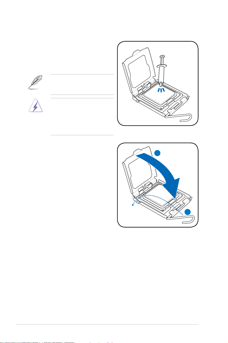
1.1.4 Intel LGA1155 Socket (1)................................................ 1-7
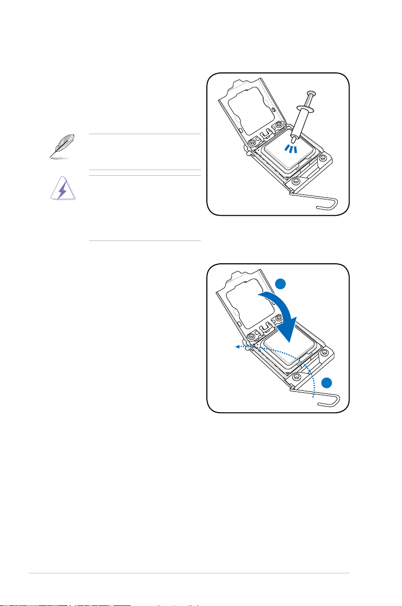
1.1.5 Intel LGA1155 Socket (2)................................................ 1-9
1.1.6 Intel LGA2011 Socket ....................................................1-11
1.1.7 AMD AM2 / AM2+ / AM3 Socket ................................... 1-15
1.1.8 AMD AM3+ Socket........................................................ 1-17
1.2 Installing the heatsink and fan.................................................. 1-19
1.3 Installing a DIMM........................................................................ 1-21
1.4 Installing the motherboard........................................................ 1-23
1.5 Installing the power supply unit ............................................... 1-24
1.6 Installing an expansion card..................................................... 1-25
1.7 Installing disk drives.................................................................. 1-26
1.7.1 PATA optical disk drive .................................................. 1-26
1.7.2 SATA optical disk drive.................................................. 1-27
1.7.3 Floppy disk drive ........................................................... 1-28
1.7.4 PATA hard disk drive ..................................................... 1-29
1.7.5 SATA hard disk drive ..................................................... 1-31
1.7.6 SAS hard disk drive ...................................................... 1-32
1.8 Front panel cables ..................................................................... 1-33
1.9 Connecting the ATX power........................................................ 1-34
1.10 Peripheral devices and accessories ........................................ 1-36
1.11 Startingupforthersttime...................................................... 1-37
Chapter 2: Manage/update BIOS
2.1 AFUDOS utility ............................................................................. 2-1
2.2 Award BIOS Flash Utility ............................................................ 2-3
2.3 ASUS Update utility ..................................................................... 2-6

iv
Contents
2.4 ASUS BIOS Updater..................................................................... 2-9
Chapter 3: Troubleshooting
3.1 Troubleshooting for Motherboard DIY ....................................... 3-1
3.1.1 Basic troubleshooting...................................................... 3-1
3.2 Other common troubles .............................................................. 3-3
3.2.1 No power......................................................................... 3-4
3.2.2 Failure to boot-up; No screen display ............................. 3-5
3.2.3 Failure to enter the operating system ............................. 3-5
3.2.4 FAQs ............................................................................... 3-6
Chapter 4: Computer care tips
4.1 Proper care of your PC................................................................ 4-1
4.2 Basic knowledge.......................................................................... 4-1
4.3 Usage knowledge......................................................................... 4-1
4.4 Tips................................................................................................ 4-2

v
Safety information
Electrical safety
•
To prevent electrical shock hazard, disconnect the power cable from the
electrical outlet before relocating the system.
•
When adding or removing devices to or from the system, ensure that the power
cables for the devices are unplugged before the signal cables are connected. If
possible, disconnect all power cables from the existing system before you add
a device.
•
Before connecting or removing signal cables from the motherboard, ensure
that all power cables are unplugged.
•
Seek professional assistance before using an adpater or extension cord.
These devices could interrupt the grounding circuit.
•
Ensure that your power supply is set to the correct voltage in your area. If you
are not sure about the voltage of the electrical outlet you are using, contact
your local power company.
•
If the power supply is broken, do not try to x it by yourself. Contact a qualied
service technician or your retailer.
Operation safety
•
Before installing the motherboard and adding devices on it, carefully read all
the manuals that came with the package.
•
Before using the product, ensure all cables are correctly connected and the
power cables are not damaged. If you detect any damage, contact your dealer
immediately.
•
To avoid short circuits, keep paper clips, screws, and staples away from
connectors, slots, sockets, and circuitry.
•
Avoid dust, humidity, and temperature extremes. Do not place the product in
any area where it may become wet.
•
Place the product on a stable surface.
•
If you encounter technical problems with the product, contact a qualied
service technician or your retailer.

vi

ASUS Motherboard installation guide 1-1
To prevent damage to the socket
pins, do not remove the PnP cap
unless you are installing a CPU.
1. Locate the CPU socket on the
motherboard.
2. Press the load lever with your thumb
(A), then move it to the left (B) until it
is released from the retention tab.
A
B
Load lever
Retention tab
3. Lift the load lever in the direction of
the arrow to a 135º angle.
4. Lift the load plate with your thumb
and forenger to a 100º angle (4A),
then push the PnP cap from the
load plate window to remove (4B).
Load plate
PnP cap
4A
4B
3
Chapter 1: Quick Start
5. Position the CPU over the socket,
making sure that the gold triangle
is on the bottom-left corner of the
socket then t the socket alignment
key into the CPU notch.
The CPU ts in only one correct
orientation. DO NOT force the
CPU into the socket to prevent
bending the connectors on the
socket and damaging the CPU!
Gold
triangle
mark
Alignment key
CPU notch
1.1 Installing the CPU
1.1.1 Intel LGA775 Socket

1-2 Chapter 1: Quick Start
6. Apply some Thermal Interface
Material to the exposed area of
the CPU that the heatsink will be
in contact with, ensuring that it is
spread in an even thin layer.
Some heatsinks come with pre-
applied thermal paste. If so, skip
this step.
7. Close the load plate (A), then push
the load lever (B) until it snaps into
the retention tab. A
B
The Thermal Interface Material is
toxic and inedible. DO NOT eat it.
If it gets into your eyes or touches
your skin, wash it off immediately,
and seek professional medical
help.

ASUS Motherboard installation guide 1-3
1.1.2 Intel LGA1366 Socket
1. Locate the CPU socket on the
motherboard.
To prevent damage to the socket
pins, do not remove the PnP cap
unless you are installing a CPU.
2. Press the load lever with your
thumb (A), then move it to the left
(B) until it is released from the
retention tab.
A
B
Load lever
Retention tab
3. Lift the load lever in the direction of
the arrow to a 135º angle.
4. Lift the load plate with your thumb
and forenger to a 100º angle.
Load plate
4
3
The CPU ts in only one correct orientation. DO NOT force the CPU into the
socket to prevent bending the connectors on the socket and damaging the CPU!
6. Position the CPU over the socket,
ensuring that the gold triangle is
on the bottom-left corner of the
socket, and then t the socket
alignment key into the CPU notch.
5. Remove the PnP cap from the CPU
socket.
PnP cap
Gold
triangle
mark
Alignment key
CPU notch

1-4 Chapter 1: Quick Start
8. Close the load plate (A), and then
push the load lever (B) until it snaps
into the retention tab. A
B
7. Apply some Thermal Interface
Material to the exposed area of
the CPU that the heatsink will be
in contact with, ensuring that it is
spread in an even thin layer.
Some heatsinks come with pre-
applied thermal paste. If so, skip
this step.
The Thermal Interface Material is
toxic and inedible. DO NOT eat it.
If it gets into your eyes or touches
your skin, wash it off immediately,
and seek professional medical
help.

ASUS Motherboard installation guide 1-5
Gold
triangle
mark
Alignment keys
CPU notches
5. Position the CPU over the socket,
ensuring that the gold triangle is on
the bottom-left corner of the socket,
and then t the socket alignment
keys into the CPU notches.
The CPU ts in only one correct
orientation. DO NOT force the
CPU into the socket to prevent
bending the connectors on the
socket and damaging the CPU!
4. Remove the PnP cap from the
CPU socket by lifting the tab only.
3. Lift the load lever in the direction
of the arrow until the load plate is
completely lifted.
PnP cap
Cap tab
Load plate
To prevent damage to the socket
pins, do not remove the PnP cap
unless you are installing a CPU.
A
B
Load lever
Retention tab
2. Press the load lever with your
thumb (A), and then move it to the
right (B) until it is released from the
retention tab.
1.1.3 Intel LGA1156 Socket
The LGA1155 CPU is incompatible with the LGA1156 socket. DO NOT install a
LGA1155 CPU on the LGA1156 socket.
1. Locate the CPU socket on the motherboard.

1-6 Chapter 1: Quick Start
The Thermal Interface Material
is toxic and inedible. DO NOT
eat it. If it gets into your eyes
or touches your skin, wash
it off immediately, and seek
professional medical help.
Some heatsinks come with
pre-applied thermal paste. If
so, skip this step.
6. Apply some Thermal Interface
Material to the exposed area of
the CPU that the heatsink will be
in contact with, ensuring that it is
spread in an even thin layer.
7. Close the load plate (A), and
then push down the load lever
(B), ensuring that the front edge
of the load plate slides under the
retention lock (C).
C
B
A
8. Insert the load lever under the
retention tab.

ASUS Motherboard installation guide 1-7
3. Lift the load lever in the direction
of the arrow until the load plate is
completely lifted.
Load plate
2. Press the load lever with your
thumb (A), and then move it to the
right (B) until it is released from the
retention tab.
1.1.4 Intel LGA1155 Socket (PnP cap on the load plate)
The LGA1156 CPU is incompatible with the LGA1155 socket. DO NOT install a
LGA1156 CPU on the LGA1155 socket.
1. Locate the CPU socket on the motherboard.
2. Be sure not to remove the PnP cap
from the CPU socket before you
install the CPU.
Load lever
Retention tab
A
B
Gold
triangle
mark
Alignment keys
CPU notches
5. Position the CPU over the socket,
ensuring that the gold triangle is on
the bottom-left corner of the socket,
and then t the socket alignment
keys into the CPU notches.
The CPU ts in only one correct
orientation. DO NOT force the
CPU into the socket to prevent
bending the connectors on the
socket and damaging the CPU!

1-8 Chapter 1: Quick Start
6. Close the load plate (A), ensuring
that the front edge of the load plate
slides under the retention lock (B).
Then push down the load lever (C).
A
B
C
7. Insert the load lever under the retention tab to remove the PnP cap from the
CPU socket.
The Thermal Interface Material
is toxic and inedible. DO NOT
eat it. If it gets into your eyes
or touches your skin, wash
it off immediately, and seek
professional medical help.
Some heatsinks come with
pre-applied thermal paste. If
so, skip this step.
8. Apply some Thermal Interface
Material to the exposed area of
the CPU that the heatsink will be
in contact with, ensuring that it is
spread in an even thin layer.

ASUS Motherboard installation guide 1-9
Gold
triangle
mark
Alignment keys
CPU notches
5. Position the CPU over the socket,
ensuring that the gold triangle is on
the bottom-left corner of the socket,
and then t the socket alignment
keys into the CPU notches.
The CPU ts in only one correct
orientation. DO NOT force the
CPU into the socket to prevent
bending the connectors on the
socket and damaging the CPU!
4. Remove the PnP cap from the
CPU socket by lifting the tab only.
3. Lift the load lever in the direction
of the arrow until the load plate is
completely lifted.
PnP cap
Cap tab
Load plate
To prevent damage to the socket
pins, do not remove the PnP cap
unless you are installing a CPU.
A
B
Load lever
Retention tab
2. Press the load lever with your
thumb (A), and then move it to the
right (B) until it is released from the
retention tab.
1.1.5 Intel LGA1155 Socket (PnP cap under the load plate)
The LGA1156 CPU is incompatible with the LGA1155 socket. DO NOT install a
LGA1156 CPU on the LGA1155 socket.
1. Locate the CPU socket on the motherboard.

1-10 Chapter 1: Quick Start
The Thermal Interface Material
is toxic and inedible. DO NOT
eat it. If it gets into your eyes
or touches your skin, wash
it off immediately, and seek
professional medical help.
Some heatsinks come with
pre-applied thermal paste. If
so, skip this step.
6. Apply some Thermal Interface
Material to the exposed area of
the CPU that the heatsink will be
in contact with, ensuring that it is
spread in an even thin layer.
7. Close the load plate (A), and
then push down the load lever
(B), ensuring that the front edge
of the load plate slides under the
retention lock (C).
C
B
A
8. Insert the load lever under the
retention tab.

ASUS Motherboard installation guide 1-11
1.1.6 Intel LGA2011 Socket
1. Locate the CPU socket on the
motherboard.
2. Press the left load lever with your
thumb (A), then move it to the left (B)
until it is released from the retention
tab.
To prevent damage to the socket
pins, do not remove the PnP cap
unless you are installing a CPU.
B
A
Load lever
B
C
A
4. Press the right load lever with your
thumb (A), then move it to the right
(B) until it is released from the
retention tab. Lift the load lever in the
direction of the arrow (C).
3. Slightly lift the load lever in the
direction of the arrow.

1-12 Chapter 1: Quick Start
7. Close the load plate.
B
A
5. Push the left load lever (A) to lift the
load plate (B).
The CPU ts in only one correct orientation. DO NOT force the CPU into the
socket to prevent bending the connectors on the socket and damaging the CPU!
Triangle
mark
6. Position the CPU over the socket,
ensuring that the triangle mark is on
the top-right corner of the socket.

ASUS Motherboard installation guide 1-13
B
A
8. Push down the right load lever (A),
ensuring that the edge of the load
plate is xed by the lever (B).
9. Insert the right load lever under the
retention tab. Remove the PnP cap
from the CPU socket.
B
A
10. Push down the left load lever (A),
and then insert the lever under the
retention tab (B).

1-14 Chapter 1: Quick Start
12. Place the heatsink on top of the
installed CPU, ensuring that the four
fasteners match the holes on the
CPU socket.
13. Twist each of the four screws with
a Philips (cross) screwdriver just
enough to attach the heatsink to
the CPU socket. When the four
screws are attached, tighten them
one by one to completely secure the
heatsink.
Tighten the four heatsink screws
in a diagonal sequence.
AB
BA
A
BB
A
The Thermal Interface Material is
toxic and inedible. DO NOT eat it.
If it gets into your eyes or touches
your skin, wash it off immediately,
and seek professional medical
help.
Some heatsinks come with pre-
applied thermal paste. If so, skip
this step.
11. Apply some Thermal Interface
Material to the exposed area of
the CPU that the heatsink will be
in contact with, ensuring that it is
spread in an even thin layer.
Other manuals for P8Z77 WS
1
Table of contents
Other Asus Motherboard manuals

Asus
Asus A7VI-VM User manual

Asus
Asus CUBX User manual

Asus
Asus B85M-K PLUS User manual

Asus
Asus TUF X299 MARK 2 User manual

Asus
Asus ROG STRIX H470-I GAMING User manual

Asus
Asus STRIX Z270E GAMING User manual

Asus
Asus Pro B760M-C User manual

Asus
Asus P8H61-M LX PLUS R2.0 User manual

Asus
Asus B85M-E User manual

Asus
Asus SP97 User manual

Asus
Asus P-P55TVP4 User manual

Asus
Asus ROG STRIX HELIOS User manual

Asus
Asus P5N32-SLI Premium User manual

Asus
Asus P4T533 User manual

Asus
Asus POLO SiS630(E) Ultra-AGP User manual

Asus
Asus M2V-TVM User manual

Asus
Asus P2Z-B User manual

Asus
Asus PRIME H370M-PLUS User manual

Asus
Asus P5GD2 Deluxe User manual

Asus
Asus ROG MAXIMUS XIII APEX User manual