vi
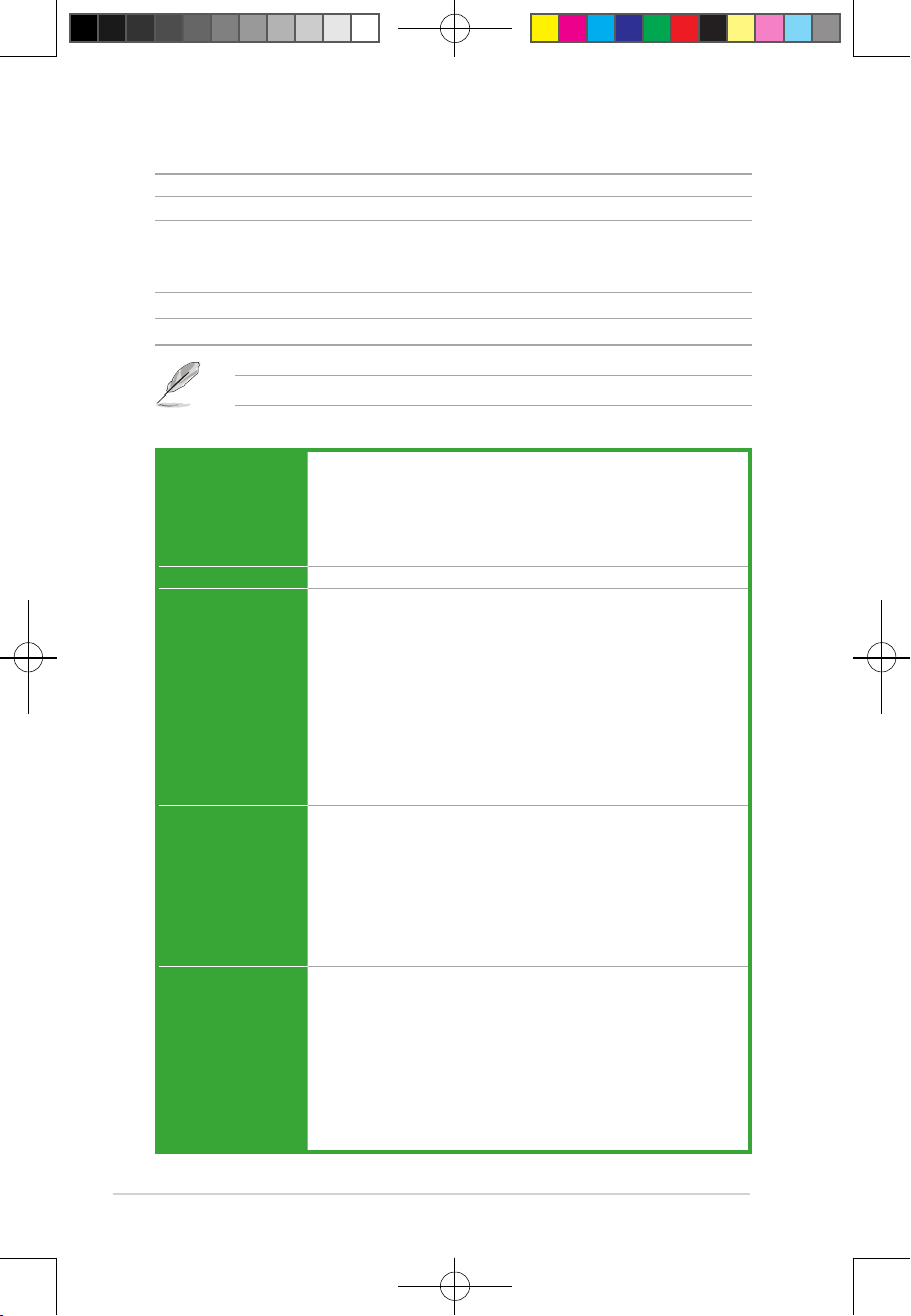
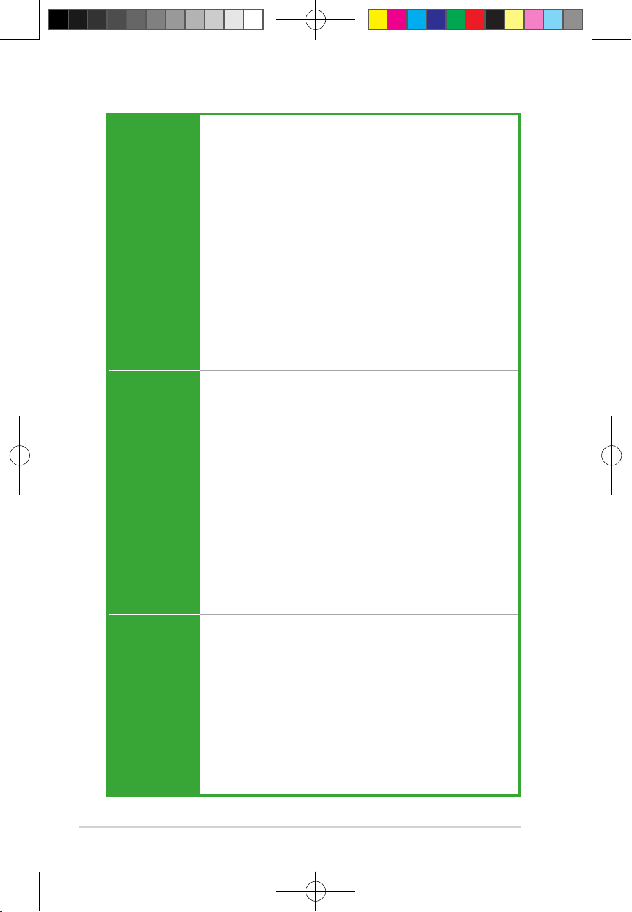
PRIME B560-PLUS specications summary
CPU
Intel®Socket LGA1200 for 11th Gen Intel®Core™ Processors & 10th Gen
Intel®Core™, Pentium®Gold and Celeron®Processors*
Supports Intel®14 nm CPU
Supports Intel®Turbo Boost Technology 2.0 and Intel®Turbo Boost Max
Technology 3.0*
* Intel®Turbo Boost Max Technology 3.0 support depends on the CPU types.
Chipset Intel®B560 Chipset
Memory
4 x DIMM, Max. 128GB, DDR4 4600(OC)/4400(OC)/4266(OC
)/4000(OC)/3733(OC)/3600(OC)/3466(OC)/3333(OC)/3200(
OC)/2933/2800/2666/2400/2133 MHz Non-ECC, Un-buffered memory
Memory*
Dual Channel Memory Architecture
Supports Intel® Extreme Memory Prole (XMP)
ASUS OptiMem
* 10th Gen Intel®Core™ i7/i9 processors support 2933/2800/2666/2400/2133 natively,
others will run at the maximum transfer rate of DDR4 2666MHz.
* 11th Gen Intel®processors support 2933/2800/2666/2400/2133 natively.
* Refer to www.asus.com for the Memory QVL (Qualified Vendors Lists), and
memory frequency support depends on the CPU types.
Graphics
1 x DisplayPort 1.2**
1 x D-Sub
1 x HDMI™ 1.4/2.0***
* Graphics specifications may vary between CPU types.
** Intel®11th & 10th Gen processors support DisplayPort 1.4 with max. resolution of
4096 x 2304 @60Hz. Please refer to www.intel.com for any updates.
***Only Intel®11th Gen processors support HDMI™ 2.0 with max. resolution of
4K@60Hz, others will only support HDMI™ 1.4 with max. resolution of 4K@30Hz.
Please refer to www.intel.com for any updates.
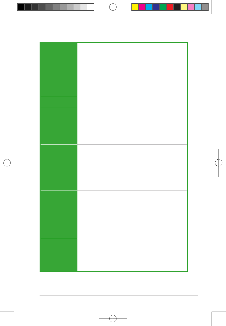
Expansion Slots
Intel®11th &10th Gen Processors
1 x PCIe 4.0/3.0 x16 slot*
- Intel®11th Gen processors support PCIe 4.0 x16 mode
- Intel®10th Gen processors support PCIe 3.0 x16 mode
Intel®B560 Chipset
1 x PCIe 3.0 x16 slot (supports x4 mode)*
2 x PCIe 3.0 x1 slots
* Enable RST PCIe Storage Remapping for PCH attached PCIe slots to activate
Intel®Optane Memory.
(continued on the next page)
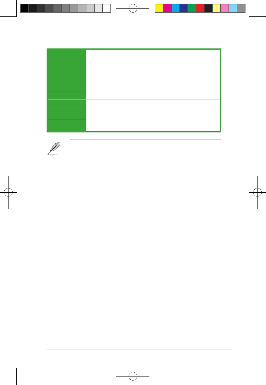
Package contents
Check your motherboard package for the following items.
Motherboard 1 x PRIME B560-PLUS motherboard
Cables 2 x SATA 6Gb/s cables
Miscellaneous
1 x M.2 Key E screw package
1 x I/O Shield
1 x M.2 Rubber package
1 x M.2 SSD screw package
Application DVD 1 x Support DVD
Documentation 1 x User manual
If any of the above items is damaged or missing, contact your retailer.
E177887_PRIME_B560-PLUS_UM.indd 6E177887_PRIME_B560-PLUS_UM.indd 6 2021/1/25 18:12:582021/1/25 18:12:58


 User manual")