vi
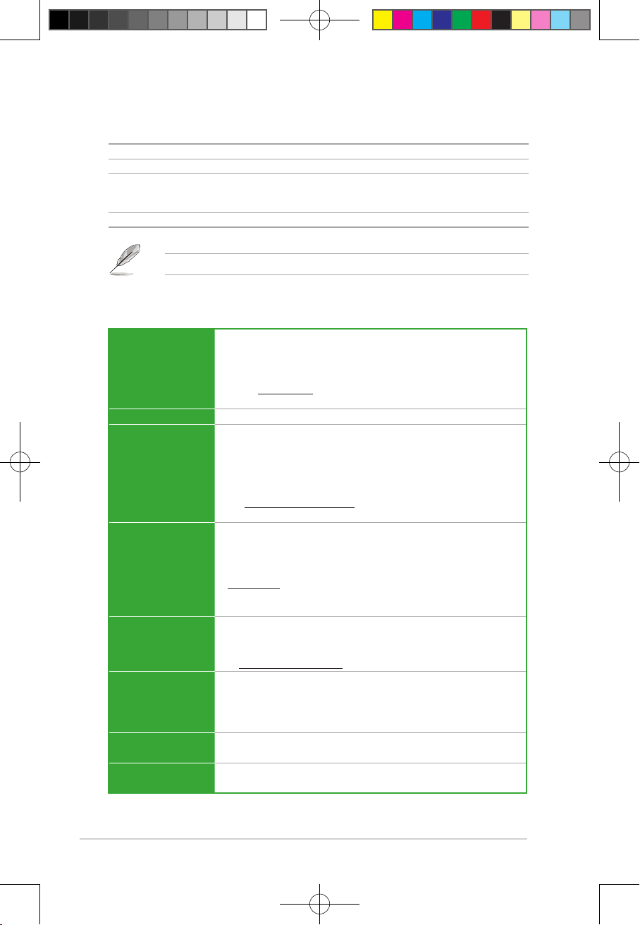
PRIME H610I-PLUS specifications summary
CPU
Intel®Socket LGA1700 for 13th Gen Intel®Core™ & 12th Gen Intel®Core™,
Pentium®Gold and Celeron®Processors*
Supports Intel®Turbo Boost Technology 2.0 and Intel®Turbo Boost Max
Technology 3.0**
* Refer to www.asus.com for CPU support list.
** Intel®Turbo Boost Max Technology 3.0 support depends on the CPU types.
Chipset Intel®H610 Chipset
Memory
2 x DIMM slots, Max. 96GB, DDR5 Non-ECC, Un-buffered Memory*
Dual Channel Memory Architecture
Supports Intel®Extreme Memory Profile (XMP)
* Supported memory types, data rate (speed), and number of DRAM modules vary
depending on the CPU and memory configuration, for more information please refer
to CPU/Memory Support list under the Support tab of product information site or
visit https://www.asus.com/support/.
* Non-ECC, un-buffered DDR5 memory supports On-Die ECC function.
Graphics
1 x DisplayPort**
1 x VGA port
1 x HDMI™ port***
* Graphics specifications may vary between CPU types. Please refer to
www.intel.com for any updates
** Supports max. 4K@60Hz as specified in DisplayPort 1.4.
***Supports 4K@60Hz as specified in HDMI™ 2.1.
Expansion Slots
Intel®13th & 12th Gen Processors
1 x PCIe 4.0 x16 slot
Note: To ensure compatibility of the device installed, please refer to
https://www.asus.com/support/ for the list of supported peripherals.
Storage
Total supports 1 x M.2 slot and 4 x SATA 6Gb/s ports
Intel®H610 Chipset
M.2 slot (Key M), type 2260/2280 (supports PCIe 3.0 x4 mode)
4 x SATA 6Gb/s ports
Ethernet 1 x Intel®1Gb Ethernet
ASUS LANGuard
Wireless &
Bluetooth
Vertical M.2 slot only (Key E, CNVi & PCIe)*
* Wi-Fi module is sold separately.
(continued on the next page)
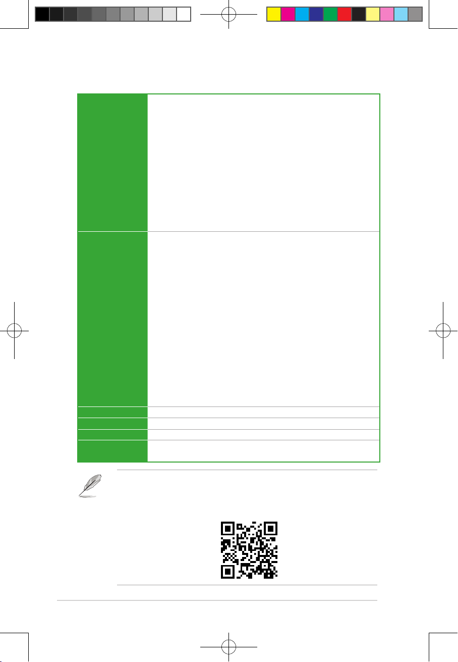
Package contents
Check your motherboard package for the following items.
Motherboard 1 x PRIME H610I-PLUS motherboard
Cables 2 x SATA 6Gb/s cables
Miscellaneous
1 x I/O Shield
1 x Screw package for M.2 SSD
1 x Vertical M.2 Key E bracket set
Documentation 1 x User guide
If any of the above items is damaged or missing, contact your retailer.
E22166_PRIME_H610I-PLUS_UM.indd 6E22166_PRIME_H610I-PLUS_UM.indd 6 2023/8/8 14:39:162023/8/8 14:39:16