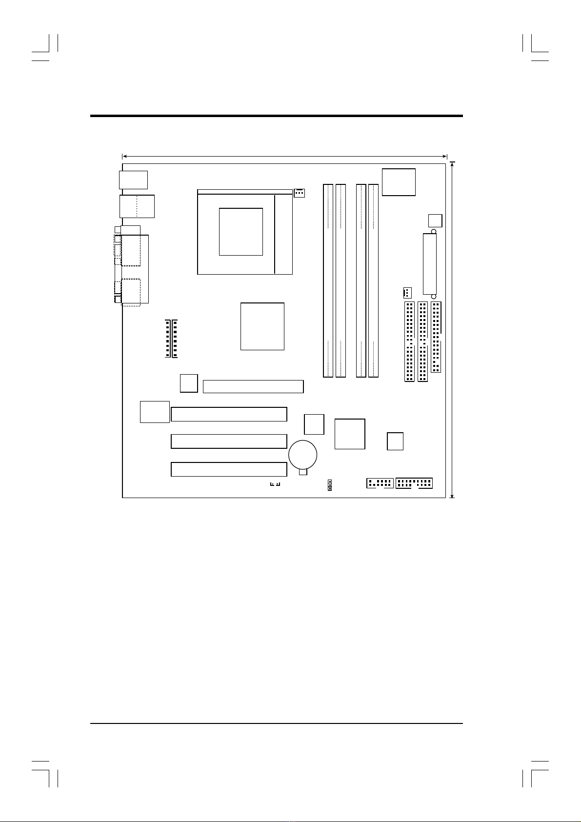
Asus WMT-LX User manual

HPWMT-LX Manual 1
WMT-LX
Intel®850 ATX Motherboard
Manual
SPECIFICATIONSAND INFORMATION CONTAINED IN THIS MANUALARE FURNISHED
FORINFORMATIONALUSE ONLY,ANDARE SUBJECTTOCHANGEATANYTIME WITH-
OUT NOTICE, AND SHOULD NOT BE CONSTRUED AS A COMMITMENT BY ASUSTeK
COMPUTER INC. ASUS ASSUMES NO RESPONSIBILITY OR LIABILITY FOR ANY
ERRORS OR INACCURACIES THAT MAYAPPEAR IN THIS MANUAL, INCLUDING THE
PRODUCTS AND SOFTWARE DESCRIBED IN IT.
Copyright © 2001 ASUSTeK COMPUTER INC. All Rights Reserved.
Product Name: HP WMT-LX
Release Date: 2001
+001-006 WMT_01.p65 3/22/01, 4:28 PM1

2HPWMT-LX Manual
1. FEATURES
1.1 WMT-LX Motherboard Layout
RJ-45
Top:
24.4cm (9.60in)
24.4cm (9.6in)
PS/2KBMS
T: Mouse
B: Keyboard
PCI1
PCI2
PCI3
PANEL
FLOPPY
SECONDARYIDE
PRIMARYIDE
Intel I/O
Controller
Hub
(ICH2)
WMT-LX
Accelerated Graphics Port (AGP)
CR2032 3V
Lithium Cell
CMOS Power
Socket 423
COM1
PARALLEL PORT
RIMMB2 (16/18 bit, 184-pin module)
RIMMB1 (16/18 bit, 184-pin module)
ATX Power Connector
RIMMA2 (16/18 bit, 184-pin module)
RIMMA1 (16/18 bit, 184-pin module)
Multi
I/O
ATX12V
Intel 850
Memory
Controller
Hub (MCH)
USB1
USB2
Top:
Realtek
RTL8139C
CPU_FAN
PWR_FAN
USB2/3
CLRTC
HP
BIOS
WOLCON
1394 HEAD
IEEE
1394
1394
Physical
Layer
Chip
1394
Link
Layer
Chip
RJ-45
Bottom:
Grayed components are available only on certain models at the time of purchase.
+001-006 WMT_01.p65 3/22/01, 4:28 PM2

HPWMT-LX Manual 3
1.2 Layout Contents
Expansion
1) RIMMA1/A2/B1/B2 p. 5 184-Pin System Memory Support
2) CPU p. 7 Central Processing Unit
3) PCI1/2/3/ p. 12 32-bit PCI Bus Expansion Slots
4) AGPPRO p. 13 Accelerated Graphics Port Slot
Connectors
1) PS2MS p.14 PS/2 Mouse Connector (Green 6-pin female)
2) PS2KB p.14 PS/2 Keyboard Connector (Purple 6-pin female)
3) PRINTER p.15 Parallel Port Connector (Burgundy 25-pin female)
4) COM1 p.15 Serial Port Connectors (Turquoise 10-1 pin male)
5) 1394_CON p.15 IEEE-1394ControllerInterface Connector (6-pin male)
6) USB p.16 Universal Serial Bus Ports (Black two 4-pin female)
7) RJ45 p.16 Fast-Ethernet Port Connector (female)
8) PRIMARY/SECONDARYIDE p.17 Primary/Secondary IDE Connectors (Two 40-1pin)
9) FLOPPY p.18 Floppy Disk Drive Connector (34-1pin)
10) 1394HEAD2/1394HEAD3 p.18 IEEE-1394 Headers (8-pin)
11) CPU_FAN, PWR_FAN p.19 POWER, CPU Fan Connectors (3 pin)
12) WOL p.20 Wake-On-LAN Connector (3 pin)
13) USB2/3 p.20 USB Header (10-1 pin)
14) ATXPWR, AUXPWR, p.21 ATX 12V Power Supply Connectors
ATX12V
15) PWR (PANEL) p.22 ATX Power / Soft-Off Switch Lead (2 pin)
16) IDELED (PANEL) p.22 IDE Activity LED (2 pin)
17) PLED (PANEL) p.22 System Power LED Lead (3-1 pin)
18) RESET (PANEL) p.22 Reset Switch Lead (2 pin)
19) MLED (PANEL) p.22 System Message LED (2 pin)
20) KEYLOCK (PANEL) p.22 Keyboard Lock Switch Lead (2 pin)
21) SMI (PANEL) p.22 System Management Interrupt Switch Lead (2 pin)
22) SPEAKER (PANEL) p.22 System Warning Speaker Connector (4 pin)
23) RTC p.23 Real Time Clock Jumper
1. FEATURES
+001-006 WMT_01.p65 3/22/01, 4:28 PM3

4HPWMT-LX Manual
2. HARDWARE SETUP
2.1 Getting Started
IMPORTANT: Due to Pentium 4 CPU’s power consumption requirement, an
ATX12V power supply is recommended for this motherboard. For typical system
configurations, anATX12V power supply that can supply at least 230W and at least
8.5A on the +12V lead is required. For heavily-loaded configurations, an ATX12V
power supply that can supply at least 300W is required.
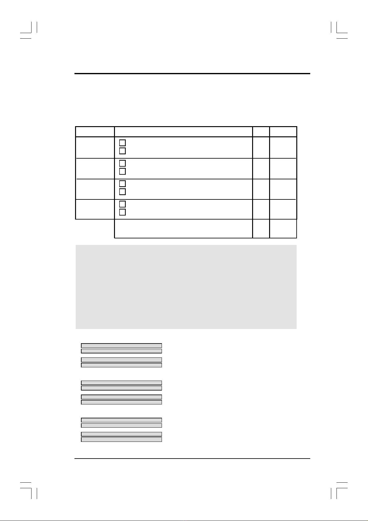
Before using your computer, you must complete the following steps:
• Check Motherboard Settings
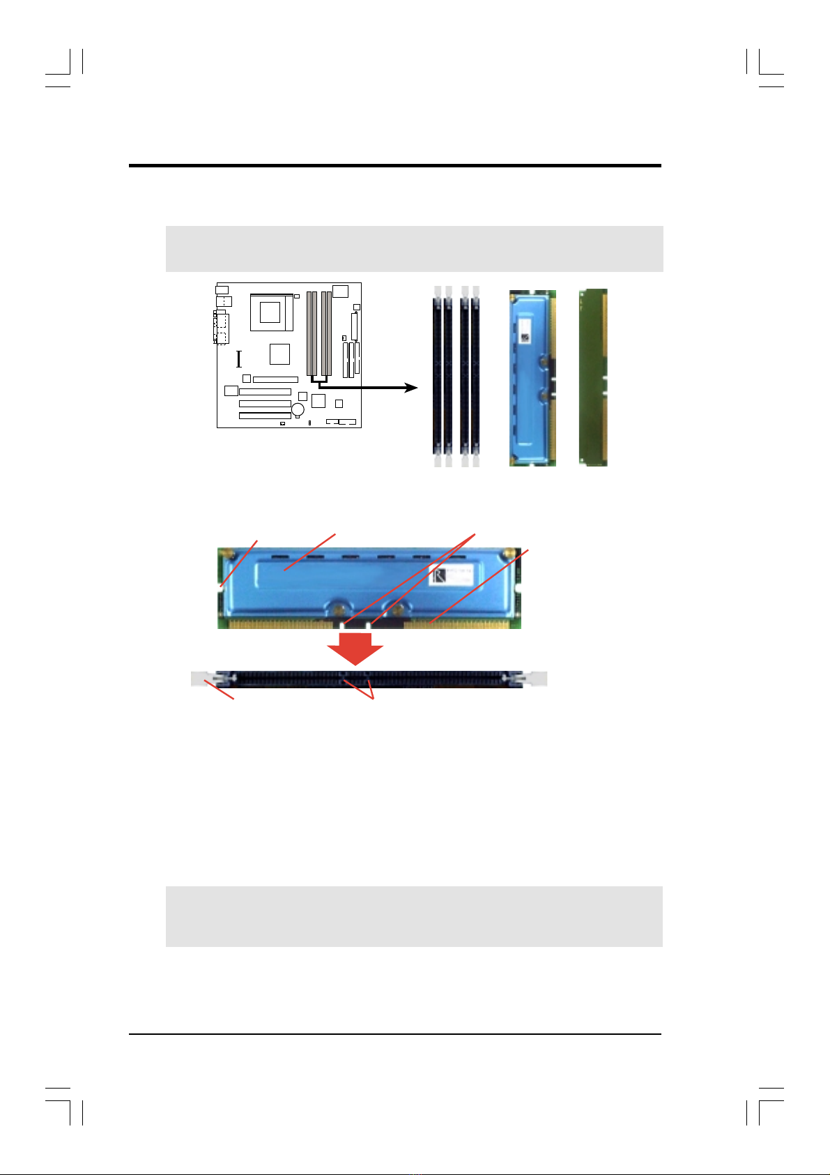
• Install Memory Modules
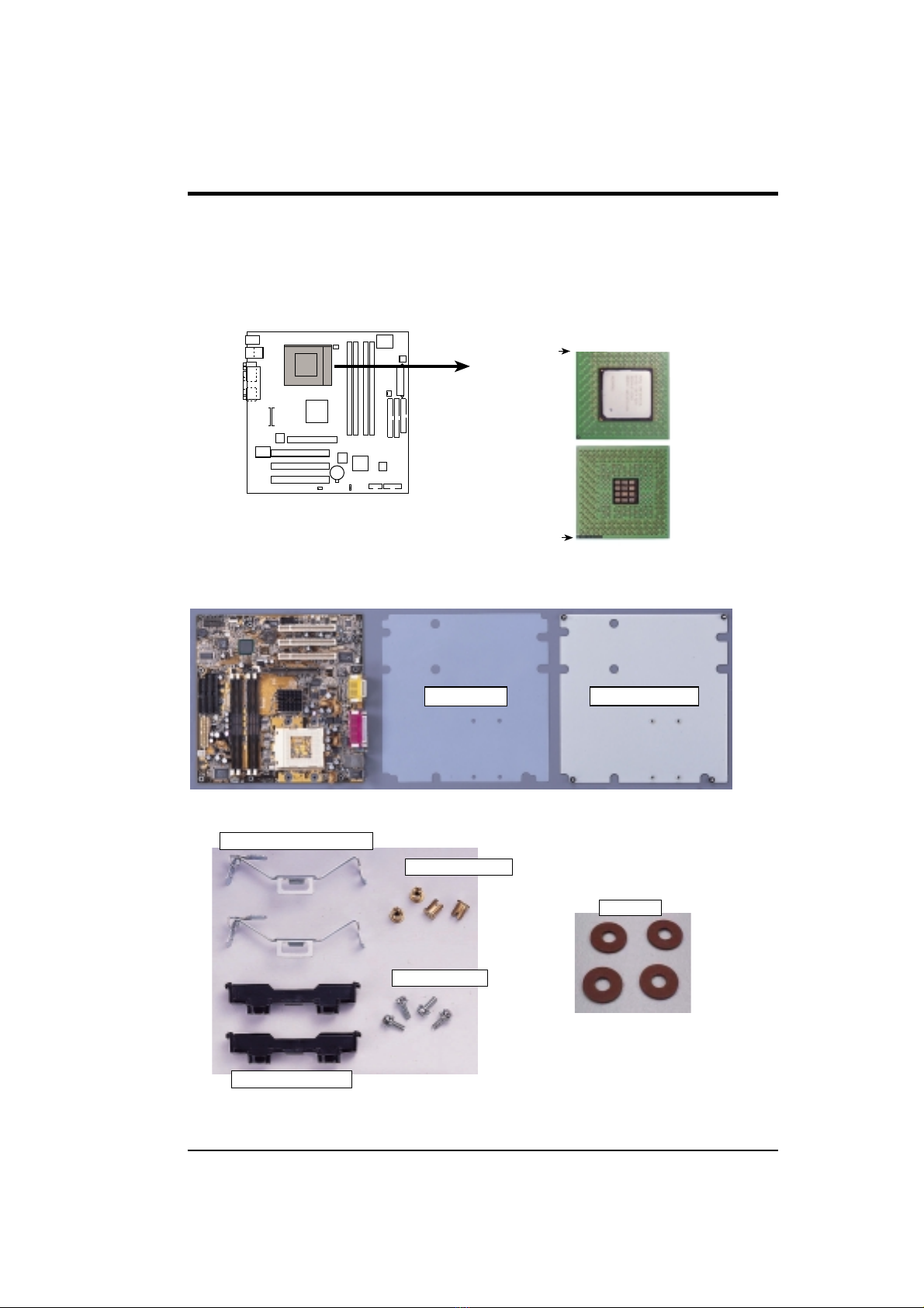
• Install the Central Processing Unit (CPU)
• Install Expansion Cards
• Connect Ribbon Cables, Panel Wires, and Power Supply
WARNING! Computer motherboards and expansion cards contain very delicate
Integrated Circuit (IC) chips. To protect them against damage from static electric-
ity, you should follow some precautions whenever you work on your computer.
1. Unplug your computer when working on the inside.
2. Use a grounded wrist strap before handling computer components. If you do
nothave one, touch both of your hands to a safely grounded object or to a metal
object, such as the power supply case.
3. Hold components by the edges and try not to touch the IC chips, leads or con-
nectors, or other components.
4. Placecomponentson a grounded antistatic pad oronthebag that came with the
component whenever the components are separated from the system.
5. Ensure that the ATX power supply is switched off before you plug in or
remove the ATX power connector on the motherboard.
WARNING! Make sure that you unplug your power supply when adding or
removing system components. Failure to do so may cause severe damage to
your motherboard, peripherals, and/or components. The onboard LED when
lit acts as a reminder that the system is in suspend or soft-off mode and not
powered OFF.
+001-006 WMT_01.p65 3/22/01, 4:28 PM4

HPWMT-LX Manual 5
2. HARDWARE SETUP
2.2 System Memory
NOTE: No hardware or BIOS setup is required after adding or removing memory.
This motherboard has four 184-pin Rambus Inline Memory Modules (RIMM) sockets.
These sockets support 64Mbit, 128Mbit, and 256Mbit Direct RDRAM technologies.
IMPORTANT
1. The memory configuration of channelA(RIMMA1 and RIMMA2) and chan-
nel B (RIMMB1 and RIMMB2) must be identical (see below).
2. C-RIMMs (Continuity RIMM) must be used to complete the sockets that are
not populated by RDRAMs. A C-RIMM is necessary to avoid breaking the
signal lines, which are a serial connection in a Rambus interface, such as
used in this motherboard. This assures the electrical integrity of a Rambus
interface.
3. When C-RIMMs are required, it is recommended that they be inserted into
RIMMA2 and RIMMB2.
RIMMA1
RIMMA2
RIMMB1
RIMMB2
128MB RDRAM
128MB RDRAM
C-RIMM
C-RIMM
a.
RIMMA1
RIMMA2
RIMMB1
RIMMB2
128MB RDRAM
128MB RDRAM
128MB RDRAM
128MB RDRAM
c.
RIMMA1
RIMMA2
RIMMB1
RIMMB2
128MB RDRAM
128MB RDRAM
C-RIMM
C-RIMM
b.
Location Memory Module Subtotal
RIMMA1 RDRAM x1
(Rows 0&1) C-RIMM (use when socket will not be populated)
RIMMA2 RDRAM x1
(Rows 2&3) C-RIMM (use when socket will not be populated)
RIMMB1 RDRAM x1
(Rows 4&5) C-RIMM (use when socket will not be populated)
RIMMB2 RDRAM x1
(Rows 6&7) C-RIMM (use when socket will not be populated)
TOTALSYSTEM MEMORY =
(2GB Max)
NOTE: When using only two memory modules,
it is recommended that you use configuration a.
+001-006 WMT_01.p65 3/22/01, 4:28 PM5

6HPWMT-LX Manual
2. HARDWARE SETUP
2.2.1 Installing Memory
The memory module (RIMM/C-RIMM) will fit in only one orientation.
IMPORTANT:Do not touch the memory module’s connectors. Handle the mod-
ule only by the edges.
1. Make sure that the notch keys in the module are aligned with the small ribs
inside the RIMM sockets.
NOTCH KEYS
CONNECTORS
RDRAM (with heat spreader)MOUNTING NOTCH
RIBS (inside socket)
EJECTOR (TOP VIEW)
2. With the ejectors in the open position (as shown), push down gently but firmly
on the memory module until it snaps into place. The guides on the socket’s
ejectors should go through the two mounting notches on the module and the
ejectors should close. If necessary, push the ejectors inward to secure the mod-
ule in place.
Removing Memory
To release a memory module, push both ejectors outward and pull the module straight
up and out of the RIMM sockets.
WARNING! RIMM modules become extremely hot during operation. To re-
duce the risk of personal injury from hot surfaces, allow the modules to cool off
before removing them.
RJ-45
Top:
WMT-LX
WMT-LX 184-Pin RIMM Sockets
RIMM Sockets
RIMM with Heat Spreader
C-RIMM
+001-006 WMT_01.p65 3/22/01, 4:28 PM6

7
2. HARDWARE SETUP
HPWMT-LX User’s Manual
2.3 Central Processing Unit (CPU)
The motherboard provides a ZIF Socket for the P4 CPU. The CPU that came with
the motherboard should have a fan attached to it to prevent overheating. If this is not
the case, then purchase a fan before you turn on your system.
RJ-45
Top:
WMT-LX
WMT-LX Socket 423
Gold Arrow
Socket 423 Pentium 4
Gold Arrow
Before you start, you should check to see that you have the following items:
Rubber Pad Metal Baseboard
2 Metal heatsink retaining clips
4 Copper captive nuts
4 Pan Head screws
2 Heatsink support bases
4 Washers

8HPWMT-LX User’s Manual
2. HARDWARE SETUP
3.5.1 CPU Installation
Step 1: Install the Baseboard
A metal baseboard is required to install the heatsink to the motherboard. A rubber
pad is placed between the metal board and motherboard to provide insulation to
prevent shorting.
Placethefourwashersoverthe four
screws on the baseboard.
Motherboard
Washer
Tighten the four copper captive
nuts over the washers.
Rubber Pad Metal Baseboard
Align the rubber pad over
the metal baseboard so that
the holes match. Align the
motherboard over the rub-
ber pad and metal base-
board so that the screws on
the baseboard match up
with the motherboard’s
screw holes.
IMPORTANT:
This step is a MUST! The washers
are necessary to prevent shorting.
Washer
Copper captive nut
®
Motherboard

9
2. HARDWARE SETUP
HPWMT-LX User’s Manual
Step 2: Install the CPU
A. L ocate the Z I F socket on the motherboard.
B . Unlock the socket by pressing the lever sidesways and then lifting it up to a
90˚–100˚angle.
C . Align the C PU over the socket such that its notched or marked corner matches
the socket’s corner near the end of the lever, while making sure that the C PU is
parallel to the socket.
D . C arefully insert the C PU into the socket until it fits in place. The illustration
below shows how to insert a C PU properly.
CAUTION!The C PU fits in only one orientation. D o not force the C PU into the
socket as it will bend the pins and damage the C PU. I t should drop into the
socket with minimal pressure. I f not, check its orientation or check for bent pins.
E . Secure the C PU into the socket by pushing the socket lever all the way down.
Y ou will hear a click indicating that the lever is in place.

10 HPWMT-LX User’s Manual
2. HARDWARE SETUP
Step 3: Install the Heatsink Support Base
Place the two heatsink support base as shown and screw in the four pan head screws.
Step 4: Install the Heatsink
C arefully place the fan heatsink on top of the heatsink support base and connect the
fan power cable to the C PU fan connector.
C onnect to the
C PU fan connector.

HPWMT-LX Manual 11
2. HARDWARE SETUP
2.4 Expansion Cards
WARNING!Unplug your power supply when adding or removing expansion
cards or other system components. Failure to do so may cause severe damage to
both your motherboard and expansion cards (see 3.3 Hardware Setup Proce-
dure for more information).
2.4.1 Expansion Card Installation Procedure
1. Read the documentation for your expansion card and make any necessary hard-
ware or software settings for your expansion card, such as jumpers.
2. Remove your computer system’s cover and the bracket plate on the slot you
intend to use. Keep the bracket for possible future use.
3. Carefully align the card’s connectors and press firmly.
4. Secure the card on the slot with the screw you removed above.
5. Replace the computer system’s cover.
6. Set up the BIOS if necessary
(such as IRQ xx Used By ISA: Yes in PNPAND PCI SETUP)
7. Install the necessary software drivers for your expansion card.
2.4.2 Assigning IRQs for Expansion Cards
Some expansion cards need an IRQ to operate. Generally, an IRQ must be exclu-
sively assigned to one use. In a standard design, there are 16 IRQs available but
most of them are already in use, leaving 6 IRQs free for expansion cards. If your
motherboard has PCI audio onboard, an additional IRQ will be used. If your moth-
erboard also has MIDI enabled, another IRQ will be used, leaving 4 IRQs free.
Standard Interrupt Assignments
IRQ Priority Standard Function
0 1 System Timer
1 2 Keyboard Controller
2 N/A Programmable Interrupt
3* 11 Communications Port (COM2)
4* 12 Communications Port (COM1)
5* 13 Sound Card (sometimes LPT2)
6 14 Floppy Disk Controller
7* 15 Printer Port (LPT1)
8 3 System CMOS/Real Time Clock
9* 4 ACPI Mode when enabled
10* 5 IRQ Holder for PCI Steering
11* 6 IRQ Holder for PCI Steering
12* 7 PS/2 Compatible Mouse Port
13 8 Numeric Data Processor
14* 9 Primary IDE Channel
15* 10 Secondary IDE Channel
*These IRQs are usually available for ISA or PCI devices.
+011-023 WMT-LX.p65 copy 3/22/01, 5:29 PM11

12 HPWMT-LX Manual
2. HARDWARE SETUP
IMPORTANT: If using PCI cards on shared slots, make sure that the drivers sup-
port “Share IRQ” or that the cards do not need IRQ assignments. Conflicts will arise
between the two PCI groups that will make the system unstable or cards inoperable.
2.4.3 Accelerated Graphics Port (AGP) Pro Slot
This motherboard provides an accelerated graphics port (AGP) pro slot to support a
new generation of AGP graphics cards with ultra-high memory bandwidth.
WMT-LX Accelerated Graphics Port (AGP)
RJ-45
Top:
WMT-LX
CAUTION!TheAGPPro slot is shipped with a warning label over the 20-pin bay.
DO NOT remove this label and the safety tab underneath it if you will be using an
AGP card without a retention notch. Removing may cause the
card to shift and may cause damage to your card, slot, and moth-
erboard. Remove ONLY when you will be using an AGP Pro
card. Use a rigid tip, such as a pen tip, to dislodge and remove
the tab from the bay. Removing the tab
Interrupt Request Table for this Motherboard
INT-A INT-B INT-C INT-D INT-E INT-F INT-G INT-H
PCI slot 1 —— ———shared ——
PCI slot 2 —————— used —
PCI slot 3 —————— —shared
AGP slot used ————— ——
USB HC0 ———used —— ——
USB HC1 —————— —shared
SMB —shared — — —— ——
AC’97 —shared — — —— ——
LAN (8139C) —————shared ——
+011-023 WMT-LX.p65 copy 3/22/01, 5:29 PM12

HPWMT-LX Manual 13
2.5 External Connectors
WARNING! Some pins are used for connectors or power sources. These are
clearly distinguished from jumpers in the Motherboard Layout. Placing jumper
caps over these connector pins will cause damage to your motherboard.
IMPORTANT: Ribbon cables should always be connected with the red stripe to
Pin 1 on the connectors. Pin 1 is usually on the side closest to the power connec-
tor on hard drives and CD-ROM drives, but may be on the opposite side on
floppy disk drives. Check the connectors before installation because there may
be exceptions. IDE ribbon cables must be less than 46 cm (18 in.), with the
second drive connector no more than 15 cm (6 in.) from the first connector.
1) PS/2 Mouse Connector (Green 6-pin PS2MS)
The system will direct IRQ12 to the PS/2 mouse if one is detected. If
one is not detected, expansion cards can use IRQ12. See PS/2 Mouse
Function Control in 4.4 Advanced Menu.
2) PS/2 Keyboard Connector (Purple 6-pin PS2KB)
This connection is for a standard keyboard using an PS/2 plug (mini
DIN). This connector will not allow standard AT size (large DIN)
keyboard plugs. You may use a DIN to mini DIN adapter on stan-
dard AT keyboards.
PS/2 Keyboard (6-pin Female)
PS/2 Mouse (6-pin Female)
+011-023 WMT-LX.p65 copy 3/22/01, 5:29 PM13

14 HPWMT-LX Manual
3) Parallel Port Connector (Burgundy 25-pin PRINTER)
You can enable the parallel port and choose the IRQ through Onboard
Parallel Port (see 4.4.2 I/O Device Configuration).
NOTE: Serial printers must be connected to the serial port.
5) IEEE-1394 Controller Interface Connector (6-pin 1394_CON)
This connector supports external digital devices.
Serial Port (9-pin Male) COM 1
4) Serial Port Connectors (Teal/Turquoise 9-pin COM1)
One serial port is ready for a mouse or other serial devices. A second
serial header is available using a serial port bracket connected from the
motherboard to an expansion slot opening. See Onboard Serial Port
1/2 in 4.4.2 I/O Device Configuration for settings.
Parallel (Printer) Port (25-pin Female)
IEEE 1394 (6-pin Male)
+011-023 WMT-LX.p65 copy 3/22/01, 5:29 PM14

HPWMT-LX Manual 15
7) Fast-Ethernet Port Connector (RJ45)
The RJ45 connector is optional at the time of purchase and is located on
top of the USB connectors. The connector allows the motherboard to
connect to a Local Area Network (LAN) through a network hub.
6) Universal Serial Bus Ports (Black two 4-pin USB)
Two USB ports are available for connecting USB devices. For addi-
tional USB ports, you can use the USB headers (see USB Headers later
in this section).
NOTE:USB Function (see 4.4.3PCIConfiguration) must be Enabled
to use these ports.
Universal Serial Bus (USB) 2
USB 1
RJ-45
+011-023 WMT-LX.p65 copy 3/22/01, 5:29 PM15

16 HPWMT-LX Manual
2. HARDWARE SETUP
8) Primary (Blue) / Secondary IDE Connectors (Two 40-1pin IDE)
These connectors support the IDE hard disk ribbon cable. Connect the
cable’s blue connector to the motherboard’s primary (recommended) or
secondary IDE connector, and then connect the gray connector to your
UltraDMA/100 slave device (hard disk drive) and the black connector
to your UltraDMA/100 master device. It is recommended that non-
UltraDMA/100 devices be connected to the secondary IDE connector.
If you install two hard disks, you must configure the second drive to
Slave mode by setting its jumper accordingly. Please refer to your hard
disk documentation for the jumper settings. BIOS now supports specific
device bootup (see 4.6 Boot Menu). (Pin 20 is removed to prevent
inserting in the wrong orientation when using ribbon cables with
pin 20 plugged).
TIP: You may configure two hard disks to be both Masters with two
ribbon cables –one for the primary IDE connector and another for the
secondary IDE connector. You may install one operating system on an
IDE drive and another on a SCSI drive and select the boot disk through
4.6 Boot Menu.
IMPORTANT: UltraDMA/100 IDE devices must use a 40-pin 80-conductor IDE
cable for 100MByte/sec transfer rates.
WMT-LX IDE Connectors
NOTE: Orient the red markings
(usually zigzag) on the IDE
ribbon cable to PIN 1.
Secondary IDE Connector
PIN 1
Primary IDE Connector
RJ-45
Top:
WMT-LX
+011-023 WMT-LX.p65 copy 3/22/01, 5:29 PM16

HPWMT-LX Manual 17
9) Floppy Disk Drive Connector (34-1pin FLOPPY)
This connector supports the provided floppy drive ribbon cable. After
connecting the single end to the board, connect the two plugs on the
other end to the floppy drives. (Pin 5 is removed to prevent inserting
in the wrong orientation when using ribbon cables with pin 5
plugged).
10) IEEE-1394 Headers (8-pin 1394HEAD2/1394HEAD3)
Theseheaderssupport an IEEE-1394serialconnector cable set thatmounts
to a standard expansion slot in the computer case. 1394-compliant inter-
nal fixed disk drives may also be connected to these headers.
RJ-45
Top:
WMT-LX
WMT-LX IEEE-1394 Headers
1394HEAD2
Ground
Ground
TPA2+
TPA2-
TPB2-
TPB2+
Ground
+12V
1394HEAD3
+12V
Ground
TPB3-
TPB3+
TPA3+
TPA3-
Ground
Ground
NOTE: Orient the red markings on
the floppy ribbon cable to PIN 1.
WMT-LX Floppy Disk Drive Connector
PIN 1
FLOPPY
RJ-45
Top:
WMT-LX
+001-023 WMT-LX.p65 copy 3/23/01, 9:32 AM17

18 HPWMT-LX Manual
11)POWER (PWR_FAN), CPU (CPU_FAN), Fan Connectors (3 pins)
These connectors support cooling fans of 350mA (4.2 Watts) or less.
Orientate the fans so that the heat sink fins allow airflow to go across the
onboard heat sink(s) instead of the expansion slots. Depending on the
fan manufacturer, the wiring and plug may be different. The red wire
should be positive, while the black should be ground. Connect the fan’s
plug to the board taking into consideration the polarity of the connector.
NOTE:The “Rotation” signal istobe used onlybyaspecially designed fan
with rotation signal. The Rotations per Minute (RPM) can monitored using
a utility such as HP PC Probe or Intel LDCM.
WARNING! The CPU and/or motherboard will overheat if there is no
airflow across the CPU and onboard heatsinks. Damage may occur to
the motherboard and/or the CPU fan if these pins are incorrectly used.
These are not jumpers, do not place jumper caps over these pins.
RJ-45
Top:
WMT-LX
WMT-LX 12-Volt Cooling Fan Power
PWR_FAN
CPU_FAN
GND
Rotation
+12V
GND
Rotation
+12V
+001-023 WMT-LX.p65 copy 3/23/01, 9:32 AM18

HPWMT-LX Manual 19
13)USB2/3 Headers (10-1 pin USB2/3)
If the USB Ports on the back panels are inadequate, a USB header is
available for two additional USB ports. Connect the 10-1 pin ribbon
cable from the provided 2-port USB connector set to the midboard 10-1
pin USB header and mount the USB connector set to an open slot on
your chassis.
WMT-LX USB Port
RJ-45
Top:
WMT-LX
1
2
11
12
GNDGND
LP2–
LP2+
SBV2 LP3–
LP3+
SBV3
USB23
12)Wake-On-LAN Connector (3-pin WOL)
This connector connects to a LAN card with a Wake-On-LAN output,
such as the HP PCI-L101 Ethernet card (see 7. Appendix). The connec-
tor powers up the system when a wakeup packet or signal is received
through the LAN card.
IMPORTANT: This feature requires that Wake On LAN or PCI Mo-
dem is enabled (see 4.5.1 Power Up Control) and that your system has
an ATX power supply with at least 720mA+5V standby power.
RJ-45
Top:
WMT-LX
WMT-LX Wake-On-LAN Connector
IMPORTANT: Requires an ATX power
supply with at least 720mA +5 volt
standby power
+5 Volt Standby PME
Ground
WOL_CON
+001-023 WMT-LX.p65 copy 3/23/01, 9:32 AM19

20 HPWMT-LX Manual
14)Power Supply Connectors (20-pin block ATXPWR)
(6-pin AUXPWR)
(4-pin ATX12V)
These connectors connect to anATX 12V power supply. Each plug from
the power supply will only insert in one orientation because of the dif-
ferent hole sizes. Find the proper orientation and push down firmly mak-
ing sure that the pins are aligned. An auxiliary power supply may be
needed depending on your system configuration.
IMPORTANT: Make sure that yourATX 12V power supply (minimum
recommended wattage: 230 watts; 300W for a fully-configured system)
can supply at least 20 amperes on the +5-volt lead and at least 720mA on
the +5-volt standby lead (+5VSB). Your system may become unstable/
unreliable and may experience difficulty in powering up if your power
supply is inadequate. ForWake-On-LAN support, yourATX power sup-
ply (minimum recommended wattage: 230watts) must supply at least
720mA +5VSB.
RJ-45
Top:
WMT-LX
WMT-LX ATX &
Auxiliary Power Connectors
ATX12V
Pin 1
ATXPWR
+3.3VDC
-12.0VDC
COM
PS_ON#
COM
COM
COM
-5.0VDC
+5.0VDC
+5.0VDC
PWR_OK
+12.0VDC
+3.3VDC
+3.3VDC
COM
+5.0VDC
COM
+5.0VDC
COM
+5VSB
+12V DCCOM
+12V DCCOM
Pin 1
+001-023 WMT-LX.p65 copy 3/23/01, 9:32 AM20
Table of contents
Other Asus Motherboard manuals

Asus
Asus P5E3 DELUXE User manual

Asus
Asus PRIME B360M-A User manual

Asus
Asus TUF H310M-PLUS GAMING User manual

Asus
Asus CUR-DLSR User manual

Asus
Asus A7V8X-MX SE User manual

Asus
Asus NRL-LS User manual

Asus
Asus K8N-LR User manual

Asus
Asus P7H55 series User manual

Asus
Asus Z11PR-D16 User manual

Asus
Asus PRIME B760M-K User manual

Asus
Asus NCLV-D2 User manual

Asus
Asus P4V8X-X User manual

Asus
Asus Striker Extreme User manual

Asus
Asus Z170-DELUXE Series User manual

Asus
Asus A55M-E User manual

Asus
Asus M3N78-EM - Motherboard - Micro ATX User manual

Asus
Asus ROG STRIX B450-E Gaming User manual

Asus
Asus Prime B350M-K User manual

Asus
Asus PRIME Z790-P WIFI Operator's manual

Asus
Asus P8H61-M LE/CSM R2.0 User manual