ASV ST50 Scout User manual

8/17/2016
Operation and Maintenance
Manual
ST50 Scout
SN All
English
All
Language:
Geographic Region:
Serial Number Range:
This manual is complements of
TrackLoaderParts.com
The world's best source for ASV parts.
Track Loader Parts 6543 Chupp Road Atlanta, Georgia 30058 USA (800)616-8156

Thank you for purchasing an ASV ST-50. With this machine, you
will be able to perform tasks not possible with other “light duty”
machines of this nature.
The ST-50 is an industrial strength, diesel powered utility vehicle. Its
rugged construction, efficient rubber track propulsion system, and
high performance 2-speed hydrostatic drive enable the ST-50 to
navigate a variety of challenging terrains with ease.
The scout is designed to be very safe, but safe operation also
requires caution and attentiveness on the part of the operator.
There are many hazards that can be encountered during operation
of an off highway utility vehicle such as the ST-50. With this in
mind, it is the responsibility of each operator to read and fully under-
stand this manual before attempting to operate the machine.
Machine damage, bodily injury, or even death may result if the pro-
cedures and precautions described in this manual are not followed
closely.
Machine Orientation
Terms like front, rear, left,
and right are used through-
out this manual to describe
portions of the machine.
They are to be understood
from the perspective of an
operator seated inside the
cab.
IINNTTRROODDUUCCTTIIOONN
1
FRONT
REAR
RIGHTLEFT

SSAAFFEETTYYOOVVEERRVVIIEEWW
2
SAFETY SYMBOL
This symbol means: Attention! Be alert!
Your safety is involved!
A safety message will follow this symbol
describing the hazard and the precautions
that need to be taken to ensure your safety.
Read and understand all safety messages in order to protect your-
self and others from personal injury or death.
These safety messages are identified by the words:
DANGER, WARNING, and CAUTION.
The word “Note” is used throughout this manual to draw your
attention to specific topics or to supplement the information
provided in that section.
It is not possible to anticipate every potential hazard. The safety
messages included in this document and displayed on the machine
are not all-inclusive. They are intended to make you aware of poten-
tial risks and encourage a safe approach to operation, inspection
and maintenance of the machine. Do not operate the machine until
you are sure you have a thorough understanding of its operation,
inspection and maintenance. It is your responsibility as the operator
to exercise caution while performing these tasks to ensure your
safety and the safety of others.
!
“DANGER” refers to an imminently hazardous situation that may
result in serious injury or even death.
DANGER
“WARNING” refers to a potentially hazardous situation that may
result in serious injury or even death.
“CAUTION” refers to a potentially hazardous situation that may result
in damage to the machine or its components.
WARNING
CAUTION
Read and understand this manual prior to operating, inspecting, or
attempting to maintain the ST-50. Performing any of these tasks incor-
rectly can lead to machine damage, personal injury or even death.
WARNING

Serial Numbers
Product ID Number (A)
The machine PIN is located
between the seats on the rear
wall of the cab interior. This
number must be provided when
contacting your dealer regarding
parts, service, warranty or
accessories. Warranty claims
will not be processed unless the
machine PIN is provided.
Engine Serial Number (B)
The engine serial number is
located on the right side of the
engine near the front, just above
the injection pump.
Manual Storage (C)
The machine manuals are
stored in the compartment locat-
ed beneath the driver’s seat.
MMAACCHHIINNEEIIDDEENNTTIIFFIICCAATTIIOONN
3
A
C
B
Remove Engine
Cover

TABLE OF CONTENTS
4
Introduction ....................................... 1
Safety Overview................................ 2
Machine Identification.................... 3
Safety ............................................................... 6
Controls .............................................................. 14
Operation........................................................... 20
Maintenance..................................................... 26
Troubleshooting.............................................. 48
Machine Specifications................................. 51
California Proposition 65.............................. 52
Recommended Fluids ................................... 53
Standard Torque Guidelines ....................... 54
Service Log........................................................ 55

5

SSAAFFEETTYY- CONTENTS
6
Features .............................................................. 7
Cargo Bed Capacity/GVW ............................ 8
Fire Prevention................................................. 9
Warning Decal Locations ............................. 10
Warning Decals................................................ 11
Dump Box Brace (if equipped)................... 13

The ST-50 is equipped with
many safety features to reduce
the possibility of injury to the
operator or passenger during
operation.
These features include:
A. Seat Belts
The seat belts are designed to
keep the operator and passen-
ger (if present) securely fas-
tened in the seats should the
machine encounter uneven ter-
rain or come to a sudden stop.
Always fasten your seat belt
prior to operating the machine.
Serious injury or even death
could result if your seat belt is
left unfastened during operation.
B. Operator Seat Belt Safety
Switch
The operator’s seat belt is
equipped with a safety switch
ensuring that the operator is
seated inside the machine with
seat belt fastened before any
motion is allowed to take place.
It is enabled by the operator
presence switch whenever the
operator seat is occupied.
C. Operator and Passenger
Presence Switches
The presence switches are acti-
vated whenever their respective
seats are occupied.
D. Passenger Seat Belt Safety
Switch
The passenger’s seat belt is
equipped with a safety switch,
enabled by the passenger pres-
ence switch, that is activated
whenever the passenger seat is
occupied. It ensures that a pas-
senger (if present) is seated
inside the machine with seat belt
fastened before any machine
movement can take place.
Note: If one or both seat belts
are unfastened during operation
(not recommended) the machine
will not come to a sudden stop
(to prevent occupant injury), but
when the operator does stop the
machine, the motion controls will
be disabled until occupant seat
belts are fastened and item F is
pressed.
SAFETY
Features
7
FE
C
A ADB
C

SAFETY
Features/Cargo Bed Capacity/G.V.W.
8
E. Auxiliary Hydraulic Safety
Switch (if equipped)
This safety device has been
included to ensure that attach-
ments do not engage when the
machine is started. It must be
locked into its neutral position in
order for the machine to start.
Note: Item E is equipped with
an orange locking tab. It must be
disengaged before the switch
can be activated. Slide the tab
downward to disengage the lock.
F. Push to Operate Switch
The ST-50 is equipped with a
switch that must be depressed
in order for the hydraulic con-
trols to function. This helps to
ensure that an operator fully
intends to operate the machine
prior to allowing track movement
or attachment function to occur.
Note: Whenever the machine is
turned off or if a seat belt has
been unfastened during motion
(not recommended) the motion
controls will be disabled. You
must make sure seat belts are
fastened, then activate the push
to operate switch (item F) to
resume operation.
Cargo Bed Capacity
The bed capacity is the amount
of weight that can be safely
applied to the bed and carried
by the ST-50.
Bed Capacity: 4000 lbs.
Note: The bed capacity specifi-
cation is the total amount of
weight that may be applied to
the bed at any given time. This
figure includes accessories that
may be attached to the bed and
any other materials that may be
applied during operation.
Example:
Dump box weight: 750 Lbs.
Material in box: 3250 Lbs.
Total weight applied: 4000 Lbs.
Gross Vehicle Weight
The G.V.W. of the ST-50 should
never exceed 9,000Lbs. during
operation. This weight excludes
an operator, but does include
any accessories, attachments or
material being moved.
Operating the machine in excess
of the the G.V.W. will void the
warranty.

Fire Prevention
The ST-50 has components that
operate at high temperatures.
Steps must be taken to make
sure that flammable items are
kept clear of these components
during operation. Failure to do
so may result in a fire.
The main heat sources in the
vehicle are the engine and the
exhaust system. The electrical
system could also be a source
of heat/sparks if damaged or
poorly maintained.
In some work environments,
flammable items may come in
contact with these sources. It is
very important that these flam-
mable items be removed often
from areas close to hot compo-
nents. If debris is allowed to
accumulate, a fire may result
posing a risk to the operator and
the machine. A fire can cause
machine damage, severe injury
or even death.
Listed are a set of precautionary
tasks that should be performed
daily or more often if necessary.
Repair or replace worn or dam-
aged components as needed to
ensure safe machine operation.
Precautionary Tasks:
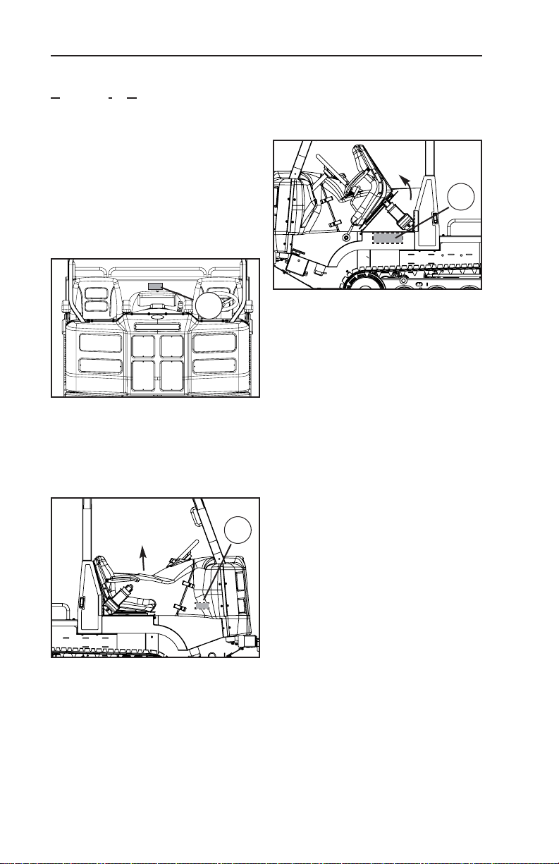
• With the engine off and cool,
remove any debris present in
the engine compartment.
Remove the belly pans and
pressure wash this area as
needed to clean it properly.
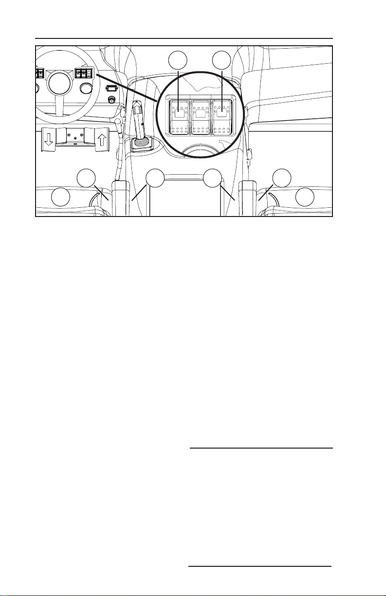
• Check the battery, fuse box,
electrical wiring and connec-
tion points for damage or
looseness.
• Check fuel lines for leaks or
damage. Never allow open
flame near fuel or fuel system
components.
• Check hydraulic lines, hoses
and fittings for damage or
leaking fluid. Never use bare
hands to check for leaks.
Pressurized fluid can pene-
trate skin and cause injury or
even death.
SAFETY
Fire Prevention
9
• Do not use ether or any other
aerosol type starting aid to
start the engine.
• Always stop the engine and
allow the machine to cool
prior to adding fuel.
• Do not smoke or allow open
flame near the machine while
refueling.
WARNING

SAFETY
Warning Decal Locations
10
A
B
B
F
D
C
C
G
E

SAFETY
Warning Decals
11
WARNING
Engine Warm-Up
Allow the engine to
warm up to operating
temperature prior to
operation.
Carrying Loads
Center loads on cargo
bed and secure to pre-
vent shifting and maxi-
mize machine stability.
Vehicle Capacity
1 operator, 1 passenger.
No Riders Permitted
Disclaimer
Failure to observe and
comply with the warn-
ings listed here may
result in machine dam-
age, personal injury, or
even death.
Pre-Start Checklist
1. Operator and passen-
ger (if present) seated
inside cab.
2. Seat belts fastened.
3. Auxiliary hydraulic
switch in neutral
position.
4. Bystanders clear of all
moving components.
Always
• Keep hands and feet
inside the cab.
• Watch for branches or
other hazards that may
enter the cab.
• Keep clear of the tracks
while the machine is in
motion.
Never
• Operate the machine
under the influence of
drugs or alcohol.
• Operate in excess of
GVW rating. (see o&m manual)
Operating Position
Never operate the
machine with any part of
your body protruding out
of the operator enclo-
sure.
Failure to do so may
result in serious injury or
even death.
Prior to Operating
Read and fully under-
stand the operation and
maintenance manual
prior to operating this
machine.
2051-678
WARNING Keep away from tracks while machine is in motion.
Serious personal injury or even death may result.
Inspect undercarriages daily for accumulation of
debris. Build-up of debris may shorten component
life and decrease machine performance.
CAUTION 2045-467
WARNING
The ROPS enclosure may not protect occu-
pants in all foreseeable accidents including,
but not limited to rollover.
2051-684
CAUTION
Load Management
When hauling cargo, always position the load so that it is centered on
the bed and orient it so that it rides as low as possible to maximize
machine stability. Properly secure all loads prior to operation.
Failure to observe or comply with precautionary notices may result in
machine damage, serious injury or even death.
2051-700
Center Load
Secure Load
A
C
B
D

SAFETY
Warning Decals
12
WARNING
No Riders
This vehicle is designed to carry one operator and one passenger
seated inside the operator enclosure with safety belts fastened.
Never allow additional passengers to ride in or on the machine.
Failure to observe or comply with warnings may result in serious
injury or even death. 2051-699
CAUTION
CARGO BED CAPACITY
4000 lb. (1814 kg)
Do not load the cargo bed in excess of the the cargo bed capacity rat-
ing. Carrying loads in excess of of this rating will void the warranty.
Failure to observe or comply with precautionary notices may result in
machine damage, serious injury or even death.
F
WARNING
Vehicle Capacity
1 operator, 1 passenger.
No Riders Permitted
Always
• Keep hands and feet
inside the cab.
• Watch for branches or
other hazards that may
enter the cab.
• Keep clear of the tracks
while the machine is in
motion.
Passenger Position
• Seated in passenger
seat.
• Seat belt fastened.
• Hands/feet inside cab. 2051-679
G
Operating with a Load
The Scout's operating characteristics can
change dramatically when carrying a load.
Terrain and maneuvers that are considered
safe when operating an unloaded machine
may not be safe when carrying a load.
Avoid inclines or side-hills when operating
with a load. Loads, especially liquids, can
shift when traversing uneven terrain. If the
load shifts during operation, it can drastically
alter the machine center of gravity and may
result in a roll-over. A roll-over can cause
machine damage, serious injury, or even
death.
Always carry loads low and as close to the
center of the machine as possible. Operate
on level ground whenever possible.
WARNING
2052-014
E

13
Dump Box Brace
The ST-50 is available with a
dump box attachment. The
dump box brace (A) is a device
used to mechanically support
the weight of the box when in
the raised position.
The dump box brace is intended
to keep personnel safe should
they need to work on the
machine with the dump box in
the raised position. It is not safe
to rely on the hydraulic system
to support dump box weight just
as it is not safe to crawl under a
machine supported only by a
hydraulic jack. The dump box
brace is used to support the
weight of the dump box much
like jack stands are used to
mechanically support vehicle
weight.
To install the dump box brace:
1. Remove any load from the
dump box (empty the box).
2. Park the machine on level
ground in a safe area for per-
forming service work.
3. Make sure any bystanders
are clear of the dump box,
then raise it to the upper limit.
4. Have an assistant pivot the
brace into position under the
box.
5. Lower the dump box slowly
until it comes to rest on the
brace.
The brace is in place. You may
now safely turn the engine off
and exit the machine.
To remove the brace:
1. Start the machine and raise
the dump box until it is clear
of the brace.
2. Have an assistant lower the
brace until it rests on the
cargo bed.
3. Once the brace has been
stowed and the assistant is
clear, lower the dump box to
the cargo bed and turn the
engine off to complete the
procedure.
SAFETY
Dump Box Brace (if equipped)
Do not work on or near a
machine wih the dump box in
the raised position unless the
dump box brace has been cor-
rectly installed.
WARNING
A

CCOONNTTRROOLLSS- CONTENTS
14
Switch Panels/Instrument Display............ 15
Motion Controls............................................... 16
Throttle/Two Speed ....................................... 17
Auxiliary Hydraulics........................................ 18

There are many instruments and
switches involved in the normal
operation of the ST-50. Make
sure to learn the location and
function of each of these items
prior to operating your machine.
Switch Panels
A. Headlight Activation Switch
B. Beacon Activation Switch*
C. Heater Fan Activation Switch*
D. Push To Operate Switch
E. 2-Speed Activation Switch
F. Continuous Flow Switch*
G. Ignition Switch
Instrument Display
H. Fuel Level Gauge
I. Warning Light Display
J. Hour Meter
K. High Range Indicator
L. Glow Plug Operation Indicator
M.Oil Pressure Warning Light
N. Coolant Temp. Warning Light
O.Hyd. Oil Temp. Warning Light
P. Battery Voltage Warning Light
Optional equipment is indicated
by an asterisk. *
The glow plug operation light
should illuminate only when the
ignition switch is turned to the
pre-heat position.
CONTROLS
Switch Panels/Instrument Display
15
A B C D E F
I H
J
G
M
O
P
N
K
L
H
I
Should item(s) M, N, or O illumi-
nate during operation, shut the
machine down immediately.
Diagnose and make any neces-
sary repairs before resuming
operation.
CAUTION

Motion Controls (and related)
Q.Bi-Directional Speed Control
R. Steering Control (wheel)
S. Throttle Control
T. Attachment Control
Steering Control
The ST-50 is equipped with a
steering wheel (R) to direct
machine movement.
• To turn the vehicle to the
right, rotate the wheel
clock wise.
• To turn the vehicle to the left,
rotate the wheel counter-
clockwise.
Note: The machine must be in
motion for the steering control to
function.
The amount the wheel is rotated
determines the degree to which
the machine turns/pivots. The
farther you turn the wheel in a
given direction, the tighter the
machine turns.
Bi-directional Speed Control
The scout is equipped with a
foot pedal (Q) that controls both
machine speed and movement
in forward/reverse directions.
• To move the machine forward,
press the right side of the
pedal gently towards the floor.
• To move the machine back-
ward, press the left side of the
pedal gently towards the floor.
Machine speed is determined by
how far the pedal is pressed
towards the floor. This applies in
forward and reverse directions.
• To move the machine slowly
press the pedal only slightly
closer to the floor then hold to
maintain desired speed.
• To move the machine at a
faster rate, press the pedal
farther toward the floor until
your desired speed is
reached and hold position to
maintain speed.
CONTROLS
Motion Controls
16
Q
R
S
T
Reverse Forward

Throttle Control
The throttle (A) controls engine
speed (RPM). When performing
work that requires delicate, pre-
cise movements, use a lower
RPM. When more speed, power,
or flow is required, use a higher
RPM.
The ST-50 is equipped with a
hand operated throttle mecha-
nism.
• To increase engine RPM,
move the hand lever forward
until the desired RPM has
been reached.
• To decrease engine RPM,
move the hand lever rear
ward.
Two Speed
The ST-50 is equipped with a
two speed hydrostatic drive sys-
tem that provides high and low
range capability.
•Low range is best suited for
strenuous tasks, maneuvering
through tight areas, or tra-
versing rough terrain.
•High range is best suited for
open areas with even terrain
where obstacles are easily
seen and avoided.
To activate high range, press the
two speed activation switch (B)
located in the right switch cluster
on the instrument display.
There is a high range indicator
light in the fuel gauge to the left
of the needle pivot. This light
illuminates when high range
operation is activated.
Note: When shifting between
ranges, slow the machine down
to ensure a smooth transition.
CONTROLS
Throttle/Two Speed
17
A
B

CONTROLS
Auxiliary Hydraulics
18
Intermittent Flow Hydraulics
(optional)
The ST-50 (if equipped) has the
capability to accept intermittent
style attachments like a dump
box or blade. These are con-
trolled with the joystick style
attachment control (C).
Note: The operator must be
seated in the cab with seat belt
fastened in order for the attach-
ment control (C) to function.
The illustration above shows the
relationship between joystick
and attachment movement.
The ST-50 is equipped with a
float function that can be used
with the blade attachment. Float
allows the blade to follow the
contours of the ground as you
move with only its own weight
acting as downforce.
To engage float:
• Pull the trigger on the front of
the joystick control.
To disengage float:
• Gently pull back on the joy-
stick until the blade moves
upward.
Continuous Flow Hydraulics
(optional)
The ST-50 is available with a
continuous flow system that can
be used to operate continuous
flow style attachments.
To activate continuous flow,
press the continuous flow switch
(D) located in the right switch
cluster in the instrument display.
Flow direction is controlled
(reversed) by pressing the top or
bottom of the switch as required.
C
D
Top-View Rear-View

19
CONTROLS
Auxiliary Hydraulics
The auxiliary hydraulics are gov-
erned by controls in the machine
circuitry that limit operation to
certain conditions.
Intermittent Flow:
• The operator must be seated
in the cab with his/her seat
belt fastened in order for the
intermittent flow hydraulics to
operate.
Continuous Flow:
• The continuous flow switch
must be locked in its neutral
positon in order to start the
machine.
• The operator is not required
to be seated in the cab for the
continuous flow hydraulics to
operate.
• In the event that the operator
exits the cab while the contin-
uous flow hydraulics are in
operation, flow will cease. You
must reactivate the continu-
ous flow switch to resume
operation.
Table of contents
Other ASV Utility Vehicle manuals
Popular Utility Vehicle manuals by other brands

Power Max
Power Max ROUGH-RIDER 700 UTV Maintenance manual

Bad Boy
Bad Boy RECOIL iS owner's manual

Tuff stuff
Tuff stuff BASECAMP owner's manual

Ingersoll-Rand
Ingersoll-Rand VR723 Operation and maintenance manual

TrailMaster
TrailMaster Challenger 300UTV-X Setup Instruction

Club Car
Club Car Carryall 295 2007 owner's manual