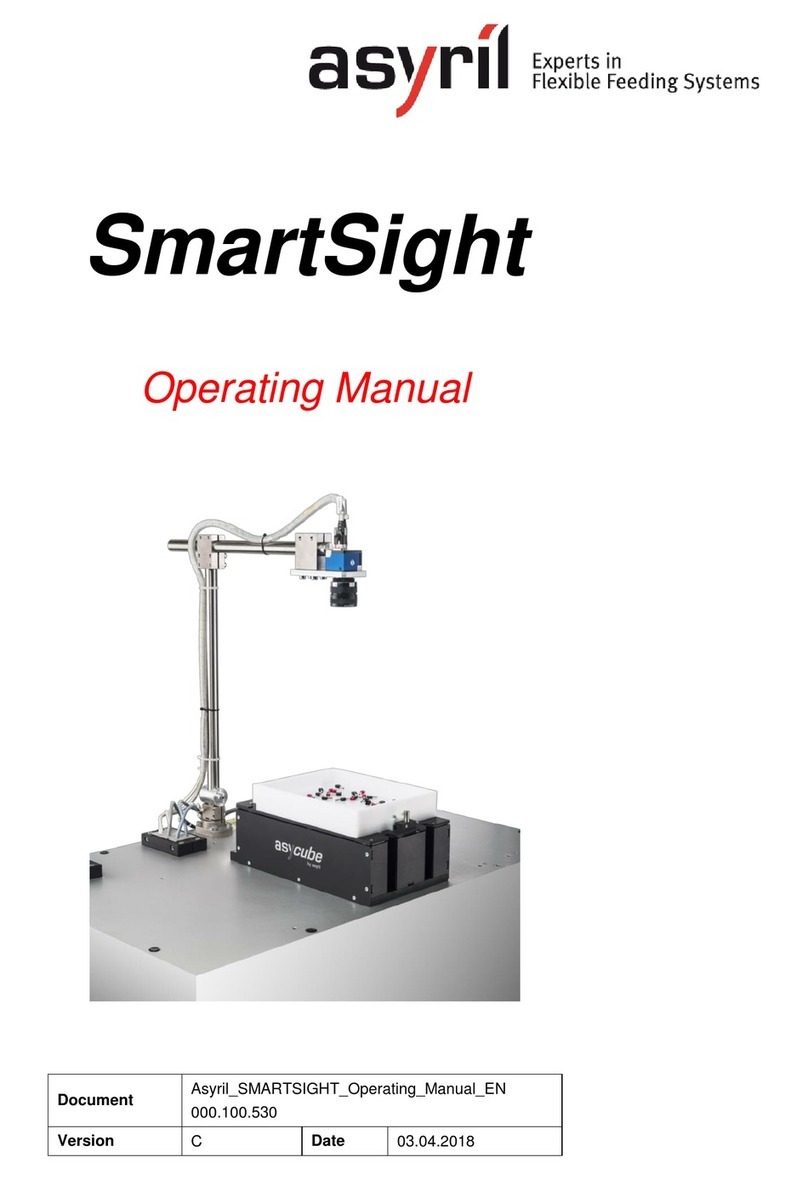
Asyril SmartSight User manual

SmartSight
User guide
Document
SMARTSIGHT_User_Guide_EN
000.100.533
Version
C2
Date
05.08.2019

© Copyright Asyril S.A.
Table of Contents
Version: C2
000.100.533 2/68
Table of Contents
TABLE OF CONTENTS..............................................................................................................................2
1. INTRODUCTION...............................................................................................................................4
1.1. GENERAL INFORMATION...........................................................................................................4
1.2. OTHER MANUALS......................................................................................................................4
2. STRUCTURE OF THE SMARTSIGHT..........................................................................................6
2.1. IMAGE CONFIGURATION AND RECIPES......................................................................................7
2.1.1. Definition of the image configuration concept ..................................................................7
2.1.2. Defining the image configuration to use..........................................................................12
2.1.3. Recipes................................................................................................................................12
3. CONFIGURING THE SYSTEM ....................................................................................................13
3.1. PIXEL/MM CALIBRATION..........................................................................................................15
3.2. CALIBRATING THE FEEDER .....................................................................................................17
3.3. CALIBRATING THE PROCESS...................................................................................................18
4. CREATION AND CONFIGURATION OF A NEW RECIPE .....................................................20
4.1. CONFIGURING THE ASYCUBE.................................................................................................21
4.1.1. Vibration of the Asycube platform and reservoir............................................................21
4.1.2. Configuring the vibration process.....................................................................................21
4.1.3. Configuring the process for two components and two hoppers ..................................24
4.2. CONFIGURATION OF THE VISION SYSTEM...............................................................................26
4.2.1. Selection of the vision analysis type................................................................................26
4.2.2. Configuring the illumination parameters..........................................................................27
4.3. PROGRAMMING THE VISION MODEL........................................................................................30
5. PROGRAMMING THE VISION MODEL.....................................................................................31
5.1. OVERVIEW ..............................................................................................................................31
5.1.1. Tips and shortcuts..............................................................................................................32
5.2. PRE-LOCALIZATION.................................................................................................................32
5.2.1. Overview..............................................................................................................................32
5.2.2. Configuring the tool: "Model" tab......................................................................................33
5.2.3. Configuring the tool: "Bounding Box" tab........................................................................38
5.2.4. Advanced mode..................................................................................................................39
5.3. MODEL FINDER.......................................................................................................................40
5.3.1. Overview..............................................................................................................................40
5.3.2. "Settings" tab.......................................................................................................................40
5.3.3. Configuring the tool: "Detection" tab................................................................................42
5.3.4. Configuring the tool: "Detection (advanced)" tab...........................................................45
5.3.5. Configuring the tool: "ControlSettings" tab .....................................................................46

© Copyright Asyril S.A.
Table of Contents
Version: C2
000.100.533 3/68
5.3.6. Configuring the tool: "Control (Model)" tab.....................................................................47
5.3.7. Configuring the tool: "Control (Advanced)" tab ..............................................................48
5.3.8. Configuring the tool: "Results" tab...................................................................................49
5.4. EXCLUSION ZONE DEFINITION ................................................................................................51
5.4.1. (Empty Picking Zone Growing) (EPZG)..........................................................................52
5.4.2. Empty Picking Zone Region (EPZR) ...............................................................................54
5.5. LOCATION RESULTS................................................................................................................59
5.6. FEEDING INFORMATION ..........................................................................................................60
6. END OF PROGRAMMING............................................................................................................61
6.1. CLOSING THE ASYVIEW TEACHING WINDOW .........................................................................61
6.2. TESTING THE VISION MODEL...................................................................................................62
6.3. PERMANENTLY SAVING THE VISION MODEL............................................................................63
7. SAVING IMAGES ...........................................................................................................................65
8. TECHNICAL SUPPORT................................................................................................................66
8.1. TO HELP US PROVIDE THE BEST SERVICE..............................................................................66
8.2. CONTACT................................................................................................................................66
REVISION TABLE.....................................................................................................................................67

© Copyright Asyril S.A.
Introduction
Version: C2
000.100.533 4/68
1. Introduction
1.1. General information
This document is the exclusive property of Asyril SA; it may not be reproduced, modified or
communicated, in whole or in part, without our prior written authorisation. For the purposes of
product improvement, Asyril SA reserves the right to modify any information contained in this
document without prior notice. Before using the product, please read this entire document in
order to ensure that the product is used correctly. However, if you encounter difficulties when
using the product, do not hesitate to contact our customer service department.
In this manual, the safety information that must be respected is split into three types: "Danger",
"Important" and "Note". These messages are identified as follows:
DANGER!
Failure to observe this instruction may result in serious physical injury.
DANGER!
This instruction identifies an electrical hazard. Failure to respect this instruction may
result in electrocution or serious physical injury due to an electric shock.
IMPORTANT!
Failure to respect this instruction may result in serious damage to equipment.
NOTE:
The reader's attention is drawn to this point in order to ensure that the product is used correctly.
However, failure to respect this instruction does not pose a danger.
Reference …
For more information on a specific topic, the reader is invited to refer to another manual or
another page of the current manual.
IMPORTANT!
Asyril cannot be held liable for damage to property or injuries to people caused by failure to
follow the instructions specified in the "Safety instructions" paragraph. It is the customer's
responsibility to inform the personnel concerned.
NOTE:
All dimensions and measurements in this manual are expressed in millimetres (mm)
1.2. Other manuals
The table below provides a list of documents supplied with the product. Each of these manuals
forms an integral part of the set of documentation associated with the product.

© Copyright Asyril S.A.
Introduction
Version: C2
000.100.533 5/68
This manual contains all the necessary information for a user to configure and use a new
process (feeding and visual recognition).
Manual name
Reference
Description of the content
Operating
manual
SMARTSIGHT_Operating_Manual_EN
Contains a technical
description of the product and
its functionalities together with
instructions for its
transportation and
maintenance
Programming
guide
SMARTSIGHT_Programming_Guide_EN
Contains information about
communication and use of the
product at the programming
level
User guide
SMARTSIGHT_User_Guide_EN
THIS MANUAL
HMI Manual
Directly accessible via the HMI
Table 1-1: Other manuals

© Copyright Asyril S.A.
Structure of the SmartSight
Version: C2
000.100.533 6/68
2. Structure of the SmartSight
The SmartSight can be broken down into 3 main elements which are described in the following
table and detailed in subsequent sections.
Element
Content
Description
Image
configurations
•Image region
•Items relating to the
camera
•Camera calibration
•Asycube calibration
•Process calibration
Fixed configurations, but it is possible to define
them as often as necessary, as this is only a
software configuration. Each vision model will
simply use one of these image configurations as
required.
Recipes
•Vibration set
•Vibration process
•Vision models
•Image acquisition
parameters
Variable configuration that can be saved and
reloaded as required.
For each model contained in the recipe, there will
be a link to a specific image configuration that will
be used to calculate the positions of the parts using
the calibrations.

© Copyright Asyril S.A.
Structure of the SmartSight
Version: C2
000.100.533 7/68
2.1. Image configuration and recipes
2.1.1. Definition of the image configuration concept
An image configuration is an element consisting of parameters which are not dependent on the
parts and which enable AsyView to function correctly and send the position of the parts
accurately. This configuration is not defined for each part specifically, but it is essential to
choose one for each model programmed. An image configuration can therefore be used for
several parts or models.
Note that everything defined in the image configuration is closely related to the camera setting,
and therefore to its field of view and resolution (see (A) in the image below).
2.1.1.1. The parameters of an image configuration
2
1
A
Figure 2-1: Parameters of the image configuration
1. Image region: Defines which part of the image is used to look for parts (an area of the
image in pixels). In most cases, this will be the whole image, which is why a default region
is already defined for this particular case.
2. Linked element: Defining the links between the elements allows you to specify "what the
camera is looking at in the defined region". There is no linked element for a control camera
since the camera is not looking at Asycube.

© Copyright Asyril S.A.
Structure of the SmartSight
Version: C2
000.100.533 8/68
2.1.1.2. Calibrations
Calibrations make it possible to match the coordinate systems of the various elements in the
system. They are closely related to the field of view and the image region, so each image
configuration will have its own calibrations.
2
1
3
Figure 2-2: Calibrations
1. The pixel/mm calibration makes it possible to convert the world coordinate system of the
camera (in pixels) to the physical system of mm (more practical). A calibration plate with a
"chequerboard" is used to define the correlation of the size of the chequerboard squares
in mm and the number of pixels in these squares. This plate can also be used to correct
distortions associated with the optical system.
This calibration is not mandatory but, if used, it is important to understand that this
calibration must be performed in the same plane as that in which the parts will be detected
(and not that in which they will be placed). There are two reasons for this:
- If the calibration is performed in another plane, one mm in the calibrated coordinate
system will not correspond to one mm in the part viewing plane (see Error!
Reference source not found.).
- The process calibration (see below), which will give the handling arm the picking
position of the part, is dependent on the pixel/mm calibration, so it is necessary to
calibrate in the same plane as the process calibration.

© Copyright Asyril S.A.
Structure of the SmartSight
Version: C2
000.100.533 9/68
Figure 2-3: Example of a calibration problem
Theoretical distance calibrated in the plane of the platform surface
Distance measured by the camera if calibrated in the plane of the platform surface
Distance measured by the camera if calibrated in the part viewing plane
It can be seen that there is an error which appears if the calibration is not carried out in the
correct plane (size and position). This can be considered negligible when the height of the
part is small, but becomes problematic if the height of the part is large or if the application
requires a high degree of accuracy.
Calibration should therefore ideally be carried out at the height of the blue plane and not of
the green plane.
2. The feeder calibration is used to transform the world coordinate system of the camera (in
pixels or in mm if the pixel/mm calibration has been performed) into the Asycube coordinate
system:
Figure 2-4: Correspondence between the vision coordinate system and the feeder

© Copyright Asyril S.A.
Structure of the SmartSight
Version: C2
000.100.533 10/68
The coordinates of the 4 corners in the two coordinate systems allow the correspondence
and orientation of the feeder to be established so that the vibrations are carried out in the
right directions (according to the orientation of the camera and/or the use of mirrors).
According to the figure shown above, this gives:
Element
X (feeder)
Y (feeder)
X (image)
Y (image)
Point 1
-1
1
0
0
Point 2
-1
-1
0
Height
Point 3
1
1
Width
0
Point 4
1
-1
Width
Height
This calibration is automatically carried out when a pixel/mm calibration of the camera is
performed. Otherwise, it must be done manually according to the orientation of the camera
in relation to the Asycube.
3. The calibration of the process (a generic term designating a robot, handling arm, etc.)
makes it possible to convert the coordinate system of the camera (in pixels or in mm if the
pixel/ mm calibration has been performed) into the coordinate system of the process. This
is essential in ensuring that the coordinates sent to the process allow it to come and pick
up the part at the right position.
The angle to be sent can be that of the vision coordinate system or that of the process, i.e.
taking into account or ignoring the process calibration.
This calibration must be performed each time the pixel/mm calibration of the camera is
changed (because the process calibration depends on the positions converted by the pixel/
mm calibration and sent by the camera).
As with the pixel/mm calibration, it is important to calibrate at the same plane as that viewed
by the camera (therefore at the height of the parts and not in the plane of the platform
surface).
Example of calibration points (viewed in pixels):
Element
X (vision)
Y (vision)
X (process)
Y (process)
Point 1
0
0
0
0
Point 2
0
Height
0
200
Point 3
Width
0
250
0
Point 4
Width
Height
250
200

© Copyright Asyril S.A.
Structure of the SmartSight
Version: C2
000.100.533 11/68
2.1.1.3. Links
As you can see, there are many links between the various elements described above:
- Link between image region, linked elements and calibrations.
- Link between the different calibrations.
Here is a summary table showing the effects of changing one of these elements:
Element modified
Region
Pixel/mm calibration
Feeder calibration
Process calibration
Field of view
x
x(1)
x
x
Region
x(1)
x(2)
x
Linked element
x
Pixel/mm calibration
x(2)
x
(1) Only if the pixel/mm calibration is used.
(2) The feeder calibration is automatically performed when pixel/mm calibration is carried out.
However, pixel/mm decalibration requires feeder calibration to be performed again manually.
The inseparable links described above mean that all of these elements are incorporated into what is
known as an "image configuration". The system allows you to define as many of them as are necessary
according to the different parts or uses of the system.

© Copyright Asyril S.A.
Structure of the SmartSight
Version: C2
000.100.533 12/68
2.1.2. Defining the image configuration to use
An image configuration must be created in the following cases:
oThe image region to be used for detection is different.
oThe elements linked to the camera are not the same.
oThe calibration of the camera must be different, for example, when the parts to be
detected have a geometry which is very different from the previously detected parts
(mainly part height).
In these cases, the first thing is to check is whether an image configuration already exists with
the required parameters. If this is not the case, you must create a new configuration.
Then decide on the image region you want to use (usually the whole image) and the camera-
related element(s) (usually an Asycube).
Once it has been created, perform the calibrations for this image configuration (look out for
high parts in order to properly calibrate at the viewing plane and not at the platform plane).
Then program your model(s) using the created image configuration. If the model has already
been created and you have been using a pixel/mm camera calibration, you can simply choose
the new image configuration for your model without having to recreate it.
2.1.3. Recipes
The recipes include the elements necessary for the operation of the system that are specific to
the part(s) to be fed. This includes:
For the Asycube:
othe vibration set
othe vibration process
For the vision part:
othe vision models
othe image acquisition parameters
More details on recipes in section Error! Reference source not found..

© Copyright Asyril S.A.
Configuring the system
Version: C2
000.100.533 13/68
3. Configuring the system
The system is pre-configured by Asyril according to the components ordered and the
corresponding architecture. By default, the manual describes the "1 Asycube + 1 camera"
system.
Figure 3-1: HMI home screen
1
Displays the architecture of connected and pre-configured peripherals
2
Access to display of all the cameras for monitoring purposes
3
- Access to the configuration steps
The figure below (Error! Reference source not found.) describes the parameters to be
adjusted and the main procedure to be applied after installation of the Asycube and the viewing
devices on the machine.
IMPORTANT!
These parameters must be set at the beginning of the machine adjustment procedure. Each
modification of these parameters alters the calibration and the recipes.

© Copyright Asyril S.A.
Configuring the system
Version: C2
000.100.533 14/68
Figure 3-2: Simplified description of the different tasks to perform when implementing
a new SmartSight configuration
See the HMI manual via the interface for detailed information on these functionalities: Live
image, image configuration, calibration.

© Copyright Asyril S.A.
Configuring the system
Version: C2
000.100.533 15/68
3.1. Pixel/mm calibration
First of all, it should be noted that this calibration is not essential. It converts the coordinate
system from pixels to mm, which is more convenient for users. In addition, this enables a
created recipe to be reused with this calibration if the camera moves or is changed (e.g.
creating a recipe using a 2 MPx camera and then switching to a 5 MPx device). This calibration
is also used to correct geometrical distortions of the optics used (which may be substantial at
low focal lengths, i.e. 8 mm). Finally, by carrying out this calibration, the Feeder calibration will
be performed at the same time thanks to the two rectangles in the centre of the plate.
If you do not want to use this calibration, then skip to the next step.
To perform pixel/mm calibration, a calibration plate is required (sold by Asyril or Cognex).
Once the calibration plate is mounted on your Asycube, go to the calibration tab of the HMI:
Figure 3-3: Pixel/mm calibration
Step 1
Select the pixel/mm calibration of the camera in the HMI.
Step 2
If necessary, change the size of the chessboard squares (tile size X and Y) according to your
plate. The squares on the standard plates for Asycubes have the following dimensions:
Asycube 50
Asycube 80
Asycube 240
Asycube 530
Tile size X
2 mm
2 mm
6 mm
-
Tile size Y
2 mm
2 mm
6 mm
-

© Copyright Asyril S.A.
Configuring the system
Version: C2
000.100.533 16/68
Step 3
Adjust the image acquisition time so that the intensity is sufficient but the squares are joined
correctly:
Step 4
Click on the "Calibrate" button.
Once calibration is complete, the calibration result changes to "calibrated".
IMPORTANT!
As shown earlier in this document, it is important to calibrate close to the height at which the
parts will be seen by the vision system and not systematically on the platform surface.
To do this, use the platform raising kits to adjust the calibration height.

© Copyright Asyril S.A.
Configuring the system
Version: C2
000.100.533 17/68
3.2. Calibrating the feeder
If you use the pixel/mm calibration, this calibration is performed automatically. Otherwise,
simply define which side of the camera image the hopper is on, in the image sent by the
camera. This will allow AsyView to perform the feeder calibration.
Figure 3-4: Feeder calibration
Step 1
Select feeder calibration.
Step 2
Click on the double arrow to define which side the hopper is on, in the image taken by the
camera. This affects the values in the correspondence table.
Step 3
If required for special configurations, enter the values in the table.
Step 4
Click on the "Calibrate" button.
Step 5
Once calibration is complete, the calibration result changes to "calibrated".

© Copyright Asyril S.A.
Configuring the system
Version: C2
000.100.533 18/68
3.3. Calibrating the process
The purpose of this calibration is to create a correspondence between a position sent by the
camera and the identical position in the coordinate system of the process (robot, handling arm,
etc.).
To do this, Asyril offers a calibration platform, which is a plate with holes.
It is therefore necessary to create a model that detects these holes, which will acquire the
positions in the vision coordinate system of the 4 external points of the platform.
The HMI process calibration tab then allows you to run the model and choose from among the
positions found those which will be used for calibration (the outermost positions of the work
surface, if possible).
As regards the positions of the process coordinate system (robot, handling arm, etc.), the robot
specialist defines the optimal method of obtaining the positions of the 4 holes in the process
coordinate system. For example:
ofeeling with a calibration tool fitted with a ball.
ousing the dedicated tool sold by Asyril
ofeeling with a pin which is inserted into the holes of the platform.
oinserting a pointed pin into the platform hole and aligning this point with another point
held by the robot.
oetc.
Figure 3-5: Process calibration

© Copyright Asyril S.A.
Configuring the system
Version: C2
000.100.533 19/68
Step 1
Choose the model which allows the calibration elements to be found (in this case, the holes).
Step 2
Take the image and analyse the selected model.
Step 3
Choose one of the results obtained and the pair of points in the table into which you want to
copy the position.
Step 4
Click on the arrow to transfer the position of the selected result to the "vision" position of the
selected pair of points.
Step 5
Fill in the 4 positions with the positions measured by the camera, and the "process" positions
according to your method of programming these points with your robot or handling arm (in
the image above, dummy values of 30 and 40 have been entered).
Step 6
If necessary, choose the source of the value of the angle you wish to receive (either the one
returned in the coordinate system of the process (robot, handling arm, etc.), or that of the
vision coordinate system (the process calibration is therefore not applied to the angle). A
constant value can be chosen if a constant angle is needed.
Step 7
Click on the "Calibrate" button.
Once calibration is complete, the calibration result changes to "calibrated".
IMPORTANT!
If this calibration has already been done before, it will be necessary to decalibrate before
starting the vision analysis, otherwise the results obtained will have values in the process
coordinate system. It is essential to have positions in the vision coordinate system (pixel or
mm) to complete the table of pairs of points.

© Copyright Asyril S.A.
Creation and configuration of a new recipe
Version: C2
000.100.533 20/68
4. Creation and configuration of a new recipe
Different levels of recipes are available to make it easier to access, load and save the different
levels of the machine as well as to combine the configurations according to the application.
A recipe is identified by the *.vrec file extension and contains all the data needed to configure
the complete vision and feeding system. The following sections contain a tutorial type
description of the configuration of a new recipe. However, the information contained in this
section also applies to modification of an existing recipe.
The various steps described in this chapter are shown in the following figure.
Figure 4-1: Standard scenario for configuring or modifying a vision and feeding recipe
Other manuals for SmartSight
4
Table of contents
Other Asyril Measuring Instrument manuals
Popular Measuring Instrument manuals by other brands

Bender
Bender LINETRAXX RCMS150 quick start guide

Renishaw
Renishaw OMP40 Installation and user guide

Pintek
Pintek DP-16VF instruction manual

Monitored Therapeutics
Monitored Therapeutics GoSpiro Spirometer Instructions for use

Velvetwire
Velvetwire Stickershock Information to user

sauermann
sauermann SI-CA 120 quick start guide

Alcohol Monitoring Systems
Alcohol Monitoring Systems SCRAM Agent reference guide

Hilti
Hilti PD-I Original operating instructions

PCB Piezotronics
PCB Piezotronics IMI SENSORS 66102ANZ2 Installation and operating manual

SMART
SMART S10 user manual

Greyline Instruments
Greyline Instruments DFM 5.0 user guide

JUMO
JUMO LOGOSCREEN 601 operating manual