Every 6 seconds, the precipitation gauge determines the weight of the collecting
bucket including its content using a resolution of 0.001 mm (= raw data). The
difference between this measured value and the basic weight of the empty collect-
ing bucket gives the current bucket content.
A special filter algorithm prevents incorrect measurement results in the process
from effects such as wind. The difference between the current bucket content and
the previous one gives the precipitation intensity in mm/min or mm/h.
These 6-second values for the precipitation intensity are added to the accumulated
precipitation amount (Accu total NRT – see below) by the OTT Pluvio2 S.
Depending on the filter algorithm run, the measured values are available as
real-time and non-real-time values:
䊳 Real-time output (RT): The OTT Pluvio2S outputs the measurement result
for intensities greater than 0.1 mm/min within a minute after occurrence of
the precipitation event. enefit: fast response time and precipitation output with
correct intensity.
䊳 Non-real-time output (NRT): The OTT Pluvio2S outputs the measurement
result 5 minutes after occurrence of the precipitation event. enefit: more
precise output with correct precipitation volume.
All measured values can be retrieved via a serial SDI-12 and RS-485 interface.
In detail, these are:
䊳 Intensity RT
䊳 Accu RT/NRT (since the last measured value sample)
䊳 Accu NRT (since the last measured value sample)
䊳 Accu total NRT (since the last reset)
䊳 ucket RT
䊳 ucket NRT
䊳 Temperature of load cell
䊳 Status OTT Pluvio2S (since the last measured value sample)
The OTT Pluvio2S provides the precipitation values using a resolution of 0.001 mm.
Individual response thresholds of ≥ 0.03 mm are applied to these values within
one hour. A detailed description of the individual measured values can be found
in Chapter 3.1.
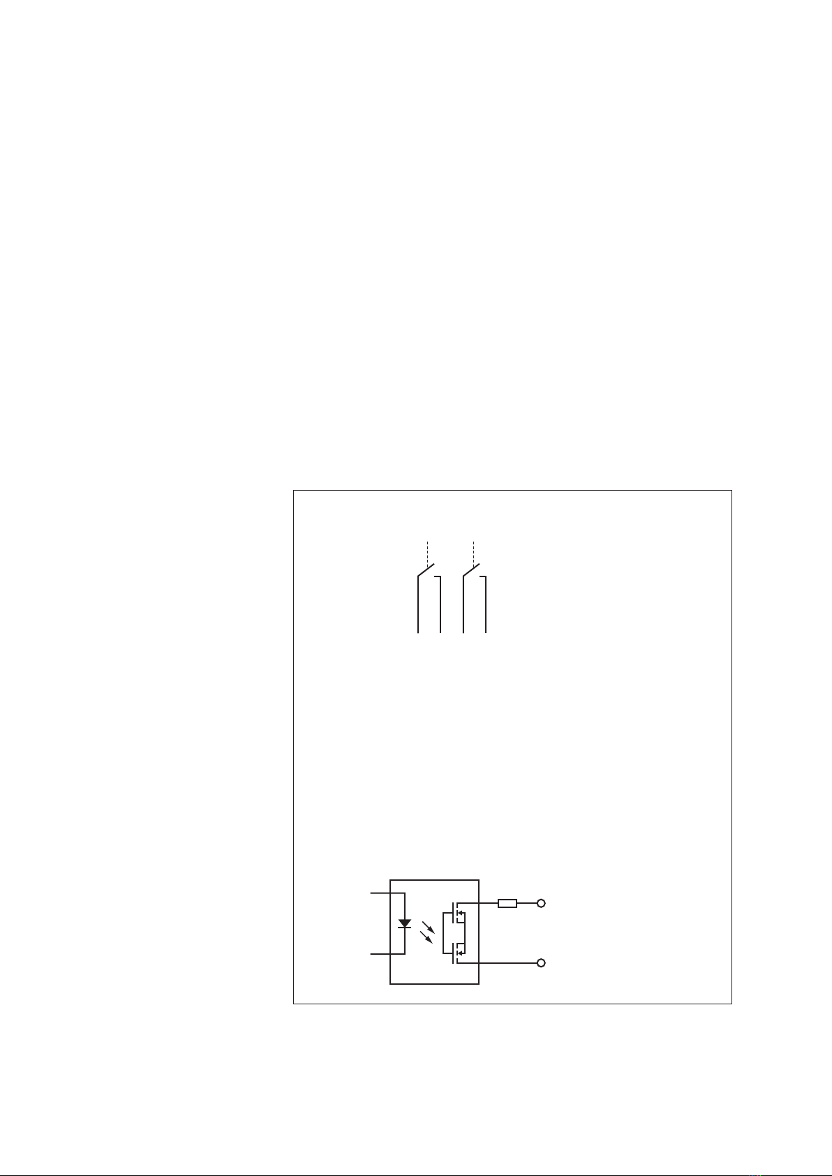
The OTT Pluvio2S uses two pulse outputs to output the amount of precipitation
RT/NRT (output #1) as well as the status information (output #2) in parallel. The
pulse factor may be selected: one pulse equals 0.05 mm, 0.1 mm, 0.2 mm,
0.5 mm or 1.0 mm of precipitation.
Parallel operation of serial interface and pulse output allows two dataloggers or
one datalogger and one PLC to be connected simultaneously.
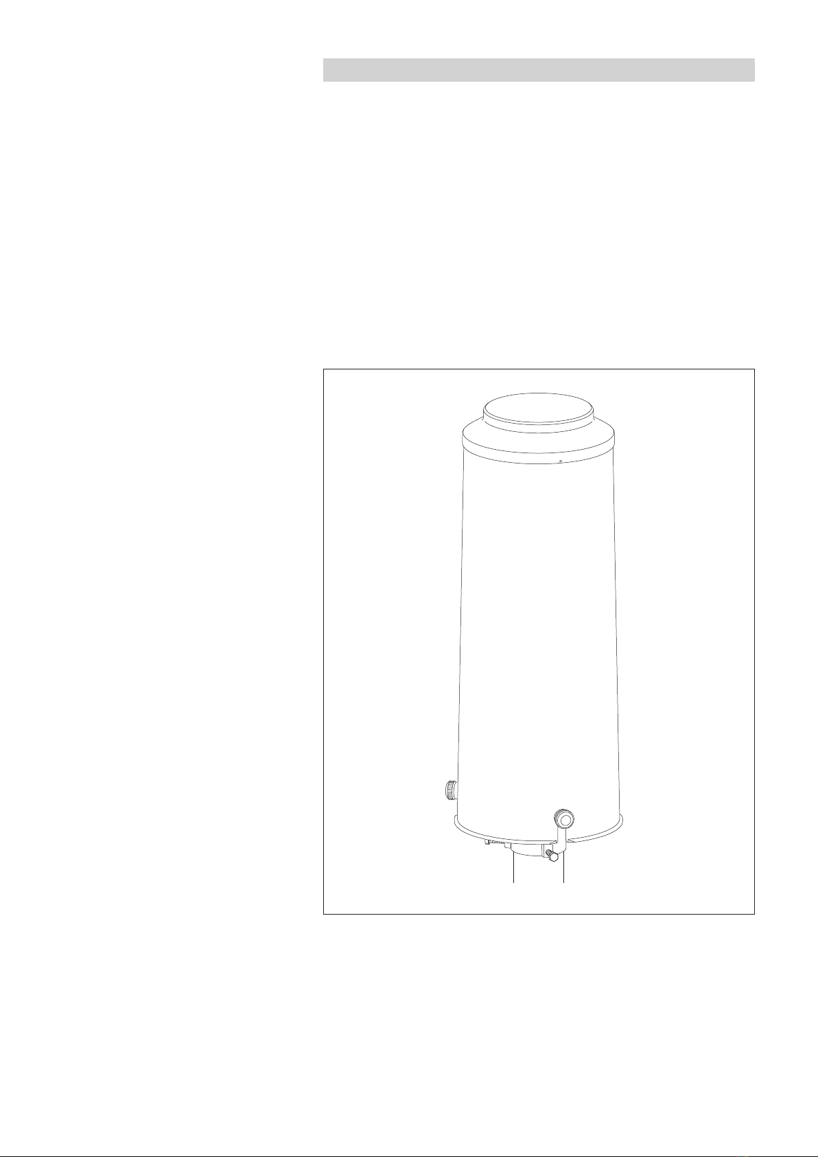
The OTT Pluvio2S is installed to a 2" pedestal the bottom plate of which is mounted
to a concrete foundation. The standard installation height is 1 meter (height of the
orifice ring rim). Alternatively, 1.2 or 1.5 meters are possible.
After connecting the supply voltage, the OTT Pluvio2S automatically starts measuring
operation (➝red LED is flashing, refer to Fig. 18). The OTT Pluvio2S is calibrated
in the factory. On site, no further calibration is necessary.
Any increases in weight greater than approx. 12 mm within 6 seconds are not output
as precipitation, as they exceed a natural level of precipitation. Thus, spurious increases
such as bucket changes or filling with anti-freeze are suppressed. Check measurements,
even with large reference weights (> 240 g), are possible using the values of ucket RT
and ucket NRT. The measured value sample is carried out in a joint data telegram with
multiple measured values. Individual samples with different intervals are not possible.
6