Alle Rechte vorbehalten.
Nachdruck und Vervielfältigung
nur mit Genehmigung des Herausgebers.
Bender GmbH & Co. KG
Postfach 1161 • 35301 Grünberg • Deutschland
Londorfer Str. 65 • 35305 Grünberg • Deutschland
Tel.: +49 6401 807-0 • Fax: +49 6401 807-259
All rights reserved.
Reprinting and duplicating
only with permission of the publisher.
Bender GmbH & Co. KG
PO Box 1161 • 35301 Grünberg • Germany
Londorfer Str. 65 • 35305 Grünberg • Germany
Tel.: +49 6401 807-0 • Fax: +49 6401 807-259
Technical data
Measuring circuit 1 (IC1) .............................................. (L1, L2, L3, N)
TN and TT system....................................................................................
Nominal voltage.................................................................400/690 V
Overvoltage category/Rated voltage.................................... III/600 V
IT system ................................................................................................
Nominal voltage........................................................................ 480 V
Overvoltage category/Rated voltage.................................... III/300 V
Nominal voltage........................................................................ 690 V
Overvoltage category/Rated voltage....................................II/1000 V
Measuring circuit 2 (IC2) ...................... (•I11, I12, •I21, I22, •I31, I32)
Overvoltage category/Rated voltage.........................................III/300 V
Supply circuit (IC3) ....................................................... (A1/+, A2/–)
Overvoltage category/Rated voltage........................................ III/300 V
Output circuit 1 (IC4) for PEM353-N and PEM353..........(DO13, DO14)
Overvoltage category/Rated voltage........................................ III/300 V
Output circuit 1 (IC4) for PEM353-P....................................(E1+, E1-)
Overvoltage category/Rated voltage.......................................... III/50 V
Output circuit 2 (IC5) for PEM353-N and PEM353......... (DO23, DO24)
Overvoltage category/Rated voltage........................................ III/300 V
Output circuit 2 (IC5) for PEM353-P................................... (E2+, E2-)
Overvoltage category/Rated voltage...........................................III/50 V
Control circuit 1 (IC6) ......................................(DIC, DI1, DI2, DI3, DI4)
Overvoltage category/Rated voltage.......................................... III/50 V
Control circuit 2 -RS485 (IC7).................................................(D+, D-)
Overvoltage category/Rated voltage.......................................... III/50 V
Supply voltage
Supply voltage.........................................AC/DC 95…250 V (±10 %)
Frequency range .................................................... DC, 47 … 440 Hz
Power consumption................................................................ < 5 VA
Measuring voltage inputs
Refer to insulation coordination
Measuring range...................................10 … 828 V (max. 120 % Un)
Rated frequency................................................................ 45…65 Hz
Internal resistance UL1-N,L2-N,L3-N ...................................> 12 MΩ
Transformation ratio of the measuring voltage transformer
...................................................................configurable (see manual)
Measuring current transformer inputs
Inom ................................................................................................ 5 A
Measuring range .................................................0.1 … 200 % Inom
Load ...................................................................................< 0.15 VA
Overload range .................................................... 2 x Inom permanent
..................................................................................... 20 x Inom ≤ 1 s
Transformation ratio of the measuring current transformer...............
...................................................................configurable (see manual)
Switching elements
Outputs ...................................................................... 2 N/O contacts
Operating principle ......................................................N/O operation
PEM353-N, PEM353
Relay contacts, N/O operation, AC 250 V or DC 30 V ......................... 5 A
Minimum current Imin .......................................... 1 mA at AC/DC ≥ 10 V
PEM353-P
Pulse output ................................................ max. DC 30 V, max. 30 mA
Cable length ............................................................................... ≤ 30 m
Inputs ........................................4 common galv. isolated digital inputs
Imin................................................................................................... 1 mA
UDI .............................................................................................. DC 24 V
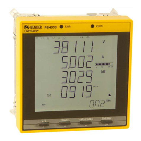
PEM353
