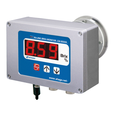
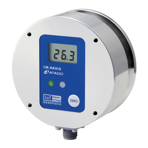
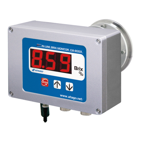
ATAGO CM-800OL User manual

1
CONTENTS
1.
Precautions for Use................................................................................................................................................ 2
2.
Refractive Index and Brix(%)............................................................................................................................. 8
(1)
What is refractometer?................................................................................................................................. 8
(2)
What is the Refractive Index?................................................................................................................... 8
(3)
Brix(%) scale..................................................................................................................................................... 8
(4)
Temperature correction................................................................................................................................ 8
3.
Unpacking and Installation.................................................................................................................................. 9
(1)
Configuration..................................................................................................................................................... 9
(2)
Unpacking .......................................................................................................................................................... 9
(3)
Installation........................................................................................................................................................10
4.
Names and Functions of Components........................................................................................................11
(1)
Main unit of the In-line Monitor...............................................................................................................11
(2)
Operation Display.........................................................................................................................................12
(3)
AC Adapter AD-32, AD-33 or AD-34 (Optional)..............................................................................12
5.
Mounting the main unit and AC adapter AD-32 (AD-33 or AD-34) (Optional)..........................13
6.
Mounting the Sample Inlet Unit......................................................................................................................14
(1)
Installation of the main unit with the sample inlet unit (optional):..........................................14
(2)
Installation of the main unit without the sample inlet unit (optional):...................................16
7.
Connecting the Power Cable or AC Adapter AD-32 (AD-33 or AD-34) (Optional).................17
(1)
When the main unit is used alone........................................................................................................17
(2)
When the AC adapter AD-32, AD-33 or AD-34 (Optional) is used........................................18
8.
External Output......................................................................................................................................................19
(1)
Recorder output.............................................................................................................................................19
(2)
RS-232C output.............................................................................................................................................20
9.
Power Supply..........................................................................................................................................................24
(1)
When the main unit is used alone........................................................................................................24
(2)
When the AC adapter AD-32, AD-33 or AD-34 (optional) is used.........................................24
10.
Measuring Brix(%)................................................................................................................................................25
11.
Setting the temperature scale (˚C/˚F)..........................................................................................................26
12.
Setting the Measurement Interval and Mode-S Level.........................................................................27
13.
Changing the Number of Decimal Places Displayed...........................................................................28
14.
Adjusting to the Reference...............................................................................................................................29
15.
Setting the Temperature Correction Values..............................................................................................30
16.
Setting the Recorder Output............................................................................................................................34
17.
Cleaning the Prism...............................................................................................................................................36
18.
Error Codes & Troubleshooting......................................................................................................................37
19.
Consumable Parts and Optional Items.......................................................................................................38
(1)
Consumable Parts........................................................................................................................................38
(2)
Optional Items................................................................................................................................................39
20.
Relationships between Brix(%) Values and Refractive Index (nD) Values.....................................40
21.
Specifications..........................................................................................................................................................41
22.
Dimensions...............................................................................................................................................................43
23.
Repair Service and Warranty Period...........................................................................................................44
24.
ATAGO CO.,LTD. Service Centers...............................................................................................................45

2
1. Precautions for Use
Introduction
Thank you for purchasing the In-line Brix-Monitor.
Before using the instrument, read this instruction manual carefully, and keep it on hand for
future reference.
For safe use --- Be sure to observe the following.
To prevent injury and damage to property, safely operate the instrument by observing the
precautions outlined in this manual.
The explanation of the indications and symbols of the precautions are as follows.
Read and understand them before continuing on to the following pages.
Explanation of indications
WARNING
If this indication is neglected and the instrument is handled
incorrectly, serious injury or death may result.
CAUTION
If this indication is neglected and the instrument is handled
incorrectly, injury and/or property damage may result.
Explanation of symbols
This symbol denotes an item of which to be warned or cautioned.
The contents of warning are described in detail in or near the △.
This symbol denotes an action that must not be performed (a prohibited item).
The contents of prohibition are described in detail in or near the ○.
This symbol denotes an action that must be performed.
The contents of instruction are described in detail in or near the ●.

3
Handling of this instrument
WARNING
◇ When measuring a substance harmful to
the human body, be aware of its
properties and wear protective gloves,
mask, etc.
◇ Immediately turn off the power (DC24V) if
the unit begins to overheat, smoke or emit
an abnormal smell.
If the AC adapter AD-32, AD-33 or AD-34
(optional) is used, remove the power
cable plug from the AC 100-240V outlet.
Fire or malfunction may result if the
instrument continues to be used. Contact
your ATAGO Distributor for an inspection.
◇ Do not attempt to repair, modify, or
disassemble the instrument yourself.
Improper servicing may result in fire,
electrical shock, or burns.
◇ If the instrument is dropped or is
subjected to a strong shock, have it
inspected by an Authorized ATAGO
Service Center.
Fire or malfunction may result if the
instrument is used.
CAUTION
◇ Do not apply water or sample to any part
of the instrument other than the surface of
the prism.
Applying water to any other part of the
instrument may result in a malfunction.
◇ Do not measure very hot or highly acidic
samples.
This may damage the prism, which would
result in inaccurate measurements.

4
Handling of this instrument (Continued)
CAUTION
◇ DO NOT measure any sample that can
damage the prism or the sample inlet unit.
◇ Cleaning liquids up to 160˚C can be used
for CIP or SIP. The momentary difference
between the sample liquid temperature
and the cleaning liquid temperature must
be no more than 80˚C.
When using cleaning liquids at
temperatures over 160˚C, the power
source (DC24V) must be turned off. If the
AD-32 (AD-33 or AD-34) is used, unplug
from the outlet before cleaning.
◇ If the sample could possibly stain the
prism, immediately clean the prism
according to the procedure described on
page 36 "17.Cleaning the Prism".
◇ The In-line Monitor power (DC24V)
should be turned off when it is not to be
used for a long period of time. If the AD
adapter AD-32, AD-33 or AD-34 (optional)
is used, disconnect the power cable plug
from the AC 100-240V outlet.
◇ When transporting the instrument, pack it
in the original box.
◇ When transporting by aircraft, disconnect
the power (DC24V) cable or the DC
output cable of the AC adapter AD-32,
AD-33 or AD-34 (optional) from the power
input terminal of the In-line Monitor.
◇ Carefully read this instruction manual and fully understand the function and operation of
each part of the instrument before use.
◇ Check that each part of the instrument operates normally before use.
◇ Perform the necessary inspections and reference adjustments according to the instruction
manual.
◇ The manufacturer shall not be held responsible for any damage that results from using the
instrument for other than its intended purposes (measurement of Brix(%), sugar content,
liquid concentration).
◇ The manufacturer shall not be held responsible if the use of the instrument has an
undesired effect on the measured materials.
◇ The prism in contact with the sample is a consumable item.

5
Handling of plug
WARNING
◇ Supply the In-line Monitor with DC24V
only (allowable fluctuation is ±10%).
Short-circuit, smoke, or fire may occur if
other voltages are used.
◇ The AC adapter AD-32 (AD-33 or AD-34)
plug must be inserted into an AC
100-240V outlet. Other outlets may result
in a short circuit, smoke, or fire.
◇ Do not use a power cable and plug that is
damaged, cut, broken, or altered.
Use may result in fire, electrical shock, or
burn.
For repair service of the power cable and
plug, contact an Authorized ATAGO
Service Center.
◇ Do not cut a plug to extend the power
cable of the AD-32 (AD-33 or AD-34).
CAUTION
◇ Do not insert or pull out the connector and
plug with wet hands.
◇ When disconnecting the power cable of
the AC adapter AD-32, AD-33 or AD-34
(optional) from the AC 100-240V outlet,
remove by pulling on the plug only.
Pulling the cable may damage it, and
could result in fire or electrical shock.
◇ Connect the grounding pin when
connecting the plug of the power cable of
the AC adapter AD-32, AD-33 or AD-34
(optional) to the AC 100-240V outlet.

6
Connection of optional component (printer, etc.)
WARNING
◇ Turn off the power (DC24V) prior to
connecting cables to the individual units.
If the AC adapter AD-32, AD-33 or AD-34
(optional) is used, pull out the power cable
plug from the AC100-240V outlet before
connecting.
Connecting the cables while the power is
on may result in electrical shock.

7
Conditions to be observed when using
Environmental conditions
◇ Use the instrument at an altitude below 2,000m (above sea level).
◇ Use the instrument indoors.
◇ Use the instrument where the temperature is between 5 to 40˚C.
◇ Do not leave the instrument in a location exposed to direct sunlight or near a heating unit
where the temperature may rise.
◇ Do not change the environmental temperature of the instrument suddenly.
◇ Do not place the instrument in a place where it may be subject to strong vibrations.
◇ Do not use the instrument where there is much dust.
◇ Do not leave the instrument where the temperature is extremely low.
◇ Do not leave the instrument in a damp place.
◇ Do not place or drop heavy objects on the instrument.
◇ Use this instrument under the condition where humidity is 80% at 31˚C or lower, falling
linearly to 50% at 40˚C.
◇ Main supply voltage fluctuation should not to exceed ±10% the nominal voltage.
◇ Installation categories (Overvoltage Categories): ll
◇ The pollution degree is 2 (according to IEC60664).
Handling
◇ Do not drop the instrument or subject it to any strong shock.
◇ The power cable may be damaged by:
•Bending the cable.
•Pulling the cable.
•Twisting the cable.
•Placing the cable under heavy objects.
•Catching the cable between objects.
Daily maintenance
◇ If the instrument becomes dirty, wipe it with a soft cloth.
◇ Do not use benzine, paint thinner, etc. to clean the instrument.

8
2. Refractive Index and Brix(%)
The In-line Brix-Monitor is a refractometer that detects the Refractive Index of a sample and
outputs the Brix(%) value on the display.
The instrument can also transmit measured data to external devices via 4 to 20mA or
RS-232C.
(1) What is refractometer?
When a straw is placed into a glass filled with water, the straw appears to bend. When a
straw is placed into a glass filled with sugar water, the straw appears to bend much more
sharply than in the case of water alone. This phenomenon is known as the refraction of
light. The refractometer is an instrument that measures the Refractive Index by utilizing
this principle (the Refractive Index increases in proportion to the concentration of the
solution), and was developed by Dr. Ernst Abbe at the end of the 19th century.
(2) What is the Refractive Index?
If the Refractive Index of air under atmospheric pressure is
1, then when light enters mediumχ, the ratio of the sine of
the incident angleαmeasured against the phase boundary to
the sine of the refracting angleβis called the Refractive
Index of the medium χ.
The Refractive Index varies with the wavelength of light and
temperature and is represented as follows:
For example, Refractive Index of water at 20˚C under the D-line is:
= 1.33299 (Generally expressed as nD = 1.33299.)
m The Refractive Index is based upon the supposition that the Refractive Index in a
vacuum is 1 and is called the absolute Refractive Index. Generally, however, this index
is seldom used.
(3) Brix(%) scale
The instrument is programmed with the Brix(%) scale, based on the Refractive Index of
water (nD = 1.33299) as the reference (0%). The Brix(%) scale represents the weight of
sucrose expressed by percentage (sucrose weight in grams contained in 100 grams of
sucrose solution).
Therefore, this scale corresponds with the sucrose concentration. However, most
samples are comprised of ingredients other than sugar. The total concentration of these
ingredients is represented by the Brix(%), so this makes the Brix(%) scale a practical tool
for measuring concentrations.
m The Brix(%) scale is recommended by ICUMSA (International Committee of Uniform
Method of Sugar Analysis) and is expressed in % mas (Sucrose) in international units
(SI unit).
C The relationship between Brix(%) and the Refractive Index (nD) is outlined on
page 40.
(4) Temperature correction
The Refractive Index of a substance varies with temperature. Thus, when using a refractometer
to measure the Refractive Index of a liquid, the measurement value will vary with the sample
temperature.
The instrument always detects the prism temperature. The value of the measurement is
automatically corrected for temperature by a built-in processor, so that the displayed value is
equal to the value measured at 20˚C (provided that the sample temperature is within the range of
5 to 100˚C).
n : Represents the Refractive Index
t : Temperature (˚C)
D : D-line of natrium (589nm)
Air
Medium χ
n=1
α
β
nχ= sin α
sin β

9
3. Unpacking and Installation
(1) Configuration
The instrument is comprised of the items listed below.
①Main unit and standard accessories.
②through ⑥are optional items and are included with the main unit if ordered.
Additional items can be ordered at any time. For details, please contact an Authorized
ATAGO Distributor.
① In-line Brix-Monitor CM-800α(Cat.No.3564)
•Main unit
•Power (DC24V) cable: approx. 1m
•O-ring (Silicon)........................ 1
•O-ring (EPDM) ........................ 1
•Instruction manual (this book)
•Inspection certificate
② AC adapter AD-32 (Cat.No. 3527), AD-33 (Cat.No. 3528) or AD-34 (Cat.No. 3529)
The AD-32 is an adapter that converts AC 100V to DC24V for supplying power to the
main unit.
The AD-33 is an adapter that converts AC 110V to DC24V for supplying power to the
main unit.
The AD-34 is an adapter that converts AC 220-240V to DC24V for supplying power to
the main unit.
③ Sample inlet unit
IDF/ISO clamp union (ferrule), IDF/ISO screw union (screw), JIS Flange, small
diameter series compression fitting and hose connector are available. Refer to page
38 "19.Consumable Parts and Optional Items".
④ Recorder output cable
•5m(Part No. RE-65374)
•10m(Part No. RE-65375)
•15m(Part No. RE-65376)
•20m(Part No. RE-65377)
•Optional length (Part No. RE-65378)
⑤ RS-232C cable
•15m
D-sub 9pin (Part No. RE-65330) D-sub 25pin (Part No. RE-5677)
•1 to 15m
D-sub 9pin (Part No. RE-65331) D-sub 25pin (Part No. RE-5647)
⑥ Stand (Part No. RE-8607) for mounting the main unit and the AD-32 (AD-33 or AD-34)
•Stand
•Hexagonal-head bolts (M6×10)8
•Spring washers ....................... 8
•Washers.................................. 8
(2) Unpacking
① Unpack the main unit and confirm that there is no external damage.
② Confirm that all parts of the main unit, accessories, and any optional units as
described in section "(1)Configuration" (Cpage 9) are included.

10
(3) Installation
CAUTION
◇ Before using the recorder output terminal or the RS-232C output
terminal, remove the two metallic caps by turning them
counterclockwise.
Fig. 3-1
① Connect the main unit to an AC100-240V main outlet (voltage fluctuations not to
exceed 10%), 50/60Hz with the power cable.
② The main unit should be supplied with DC24V (allowable fluctuation is ±10%).
The AC adapter AD-32, AD-33 or AD-34 (optional) should be connected to a power
supply of AC 100-240V, 50/60 Hz.
③ The instrument should be installed in a location with an ambient temperature of 5 to
40˚C.
④ Because the instrument incorporates highly precise components, DO NOT install in
locations exposed to direct sunlight or near a heating source, or in an environment
that is dusty or exposed to corrosive gasses.
⑤ The instrument should be installed in a location that is free from vibration. When
installing, take special care to avoid any strong shock to the instrument.
⑥ Do not touch the prism surface with your hand. Finger-prints left on the prism surface
may cause sample to build up on the prism.
In the event of contact with the prism surface, clean carefully with a soft tissue soaked
with ethyl alcohol.
In order to prevent scratches, never clean the prism surface using abrasive materials.

11
4. Names and Functions of Components
(1) Main unit of the In-line Monitor
① Prism
Sample material contacts the prism surface
to allow for the measurement of its Brix(%).
② Prism stage
Connected to the sample inlet and fastened
by a clamp band.
③ Radiator
Disperses heat when measuring high
temperature samples to prevent the electric
circuit from overheating.
④ Mounting screw locations
Used to mount the main unit to the stand.
⑤ Operation display
Comprised of the operation keys and
display
C "(2)Operation Display" page 12.
⑥ Power (DC24V) input terminal
Terminal to connect the power cable (for
DC24V input) or the DC output cable of the
AC adapter AD-32, AD-33 or AD-34
(optional).
⑦ RS-232C output terminal
Terminal to connect to a computer.
⑧ Recorder output terminal
Terminal to connect to a recorder.
Fig. 4-1
Fig. 4-2
⑥
⑦
⑧
⑤
③
④
①
②
④

12
(2) Operation Display
① Measurement value display
Digitally displays the measurement value
[Brix(%)], setting mode, and other setting
values.
② key
Switches or sets the display mode of the
measurement value and the setting mode.
Setting
mode
number Setting description
[t] Temperature scale
[0] Measurement Interval and Mode-S
Level
[1] Adjustment to the reference
[2] Temperature correction factor
[3] Recorder output, lower limit
value
[4] Recorder output, upper limit
value
[5] Changing the Number of
Decimal Places Displayed
③ Up and down keys
Increase or decrease the value in each
setting mode.
The down key also switches the display
of each setting mode.
The temperature is displayed when press the
down key while measuring a sample.
Fig. 4-3
(3) AC Adapter AD-32, AD-33 or AD-34 (Optional)
① Power cable
Connects to the AC 100-240V outlet.
② DC output cable
Connects to the output DC24V.
③ Pilot lamp
Functions when AC 100-240V is being input
and DC24V is being output.
④ Mounting screw holes
These holes are used to mount the AD-32,
AD-33 or AD-34 to the stand.
Fig. 4-4
Fig. 4-5
①
② ③
④
③
①
②

13
5. Mounting the main unit and AC adapter AD-32
(AD-33 or AD-34) (Optional)
WARNING
◇ Turn off the power (DC24V) before mounting. If AD-32 (AD-33 or
AD-34) is used, disconnect the power cable's plug from the AC
100-240V outlet before beginning.
Electrical shock may occur if the unit is mounted with the power
connected.
① Mounting screws (Fig. 5-1, Fig. 5-2)
The main unit and the AD-32 (AD-33 or
AD-34) each have four mounting screw
locations.
Use the screws supplied with the stand to
mount the main unit and AD-32 (AD-33 or
AD-34) on the stand or panel plate.
The depth of the screw locations is 10mm,
M6.
Main unit
Fig. 5-1
AD-32, AD-33 or AD-34
Fig. 5-2
Example of screw configuration (Fig. 5-3)
① Main unit or AD-32 (AD-33 or AD-34)
② Washer (M6)
③ Spring washer (M6)
④ Hexagonal-head bolt M6×10
m Hexagonal-head bolts, spring washers
and washers are included as standard
accessories with the stand (optional).
N Length of the hexagonal-head bolt =
(Screw hole depth, 10mm) + (Panel
plate length)
Mounting on a stand (optional) (Fig. 5-4)
C For information on ordering a stand,
see page 38.
Fig. 5-3
Fig. 5-4
③
①
②
④
①
148mm
98mm
①
148mm
98mm

14
6. Mounting the Sample Inlet Unit
WARNING
◇ Turn off the power (DC24V) before mounting. If AD-32 (AD-33 or
AD-34) is used, disconnect the power cable's plug from the AC
100-240V outlet before beginning.
Electrical shock may occur if the unit is mounted with the power
connected.
CAUTION
◇ Ensure that the prism is clean and free of any damage and/or
scratches. Completely remove any sample before installing the
main unit to piping or equipment.
(1) Installation of the main unit with the sample inlet unit (optional):
Compression Fitting Hose connector
Straight type L type Fig. 6-1

15
Mounting procedure
① Install the main unit so that the prism
surface is at a right angle to the ground.
② Attach the sample inlet unit to the main unit
with O-ring (accessory) inserted between
them, and fasten them together with the
clamp band (accessory).
③ Install the inlet unit so that the sample
solution runs from the lower nozzle to the
upper nozzle to prevent air bubbles from
forming.
④ When connecting the tubes to the hose
connector, clamp them with a tie band.
C"Use of tie bands" page 16
⑤ The prism surface may become
contaminated with solids, dirt and/or
grease. If this happens, the prism surface
must be cleaned by hand.
C"17.Cleaning the Prism" page 36
The sample inlet unit should be installed in
such a manner that it can be easily
removed to allow access to the prism for
cleaning.
N Suspending the main unit (2.4kg) when
using the sample inlet unit to connect
to the piping is dangerous.
Use of the optional stand is
recommended.
C"5.Mounting the main unit and AC
adapter AD-32 (AD-33 or AD-34)
(Optional)" page 13
C"19.Consumable Parts and
Optional Items" page 38
Fig. 6-2
Fig. 6-3
Fig. 6-4
Top
Bottom
Prism
stage
Flow of
solution
O-ring
(silicon or
EPDM)
Flow of solution
Clamp band
Prism stage
O-ring
(silicon or EPDM)
Sample inlet
unit
(optional
)

16
● Use of tie bands
(Hose connector (Part No. RE-67501) only)
The hose connector (Part No. RE-67501) comes with tie bands as shown in Fig. 6-5.
① Insert an end of tube onto the nozzle so that the
tube is tightly put on the nozzle.
② To fasten the tube with the tie band, insert the tip
of the tie band into the slot (Fig. 6-6).
③ While holding the tie band by the part A, pull the
tip (B) of the tie band to tighten it (Fig. 6-7).
④ After tightning the tie band, cut the tie band by
the part C for cutting off the extra (Fig. 6-8).
m The tie band that were tightened once
cannnot be reused.
For removing the tie band from the tube, cut
it.
For fastening the tube with a tie band again,
use a new tie band.
m The tie bands are made of plastic. If
measuring chemicals that are corrosive to
plastic, use tie bands made of an alternative
material.
N Tie bands can be ordered through your
ATAGO Distributor.
C"19.Consumable Parts and Optional
Items" page 38
Fig. 6-5
Fig. 6-6
Fig. 6-7
Fig. 6-8
(2) Installation of the main unit without the sample inlet unit (optional):
Please note the following when installing the main unit to piping or equipment without
using a sample inlet unit (optional):
•The size of the prism stage of the main unit is a 3S ferrule.
The ferrule connection is recommended for installation.
•Install the main unit so that the prism surface is at a right angle to the ground.
•Connect the unit to the piping so that the sample flow directly contacts the prism
surface.
The direct flow of samples (and self cleaning solutions) in contact with the prism will
keep substances from adhering to the prism surface.
•When installation to a solution tank is preferred, allow the sample flow to directly
contact the prism surface.
•The sample solution must remain in the temperature range of 5 to 100˚C.
•During operation, build up of solids, dirt and/or grease may form on the prism surface.
When this occurs, the prism surface must be manually cleaned (C"17.Cleaning the
Prism" page 36).
For ease of cleaning, the main unit should be installed in such a manner so that the
unit can be easily removed from the piping or solution tank.
C
A
B

17
7. Connecting the Power Cable or AC Adapter AD-32
(AD-33 or AD-34) (Optional)
WARNING
◇ Turn off the power (DC24V) when connecting or disconnecting
the power cable (for DC24V) or the DC output cable of the AD-32
(AD-33 or AD-34) to or from the terminal. When AD-32 (AD-33 or
AD-34) is used, remove the power cable plug from the AC
100-240V outlet.
CAUTION
◇ Disconnect the power cable or the DC output cable of the AD-32
(AD-33 or AD-34) from the power input terminal of the main unit
when transporting the main unit by aircraft.
(1) When the main unit is used alone
① Connect the power (DC24V) input cable
connector (provided) to the power (DC24V)
input terminal located at the bottom of the main
unit.
Connect the opening of the input terminal with
the connector pin and insert the connector.
Then fasten the connector by turning the
connector ring clockwise. To disconnect the
power cable, fully turn the connector ring
counterclockwise and remove the connector.
② Connect the power (DC24V) input cable
terminal to the power supply of DC24V as
illustrated in Fig. 7-1.
m At this stage, keep the DC24V power off.
Fig. 7-1
Power (DC24V) input cable and code information table.
Fig. 7-2
Pin No. Code color
3 Brown +24V
4 Blue GND
Waterproof connector plug
Approx.1m
Approx.5cm
Corner tip open terminal
1
2
4
3
To input DC24V
Power (DC24V) input cable

18
(2) When the AC adapter AD-32, AD-33 or AD-34 (Optional) is used
Attach the connector of the DC output cable of the AD-32 (AD-33 or AD-34) to the power
(DC24V) input terminal at the bottom of the main unit.
Connect the opening of the input terminal with the connector pin and insert the connector.
Then turn the connector ring clockwise to fasten the connector.
To disconnect the DC output cable, fully turn the connector ring counterclockwise and
remove the connector.
m At this stage, keep the plug disconnected from the AC 100-240V outlet.
m When AD-32 (AD-33 or AD-34) is used, the power (DC24V) input cable provided
with the main unit is not used.
Fig. 7-3
AD-32 (AD-33 or AD-34)
DC output cable
(approx. 1m in length)

19
8. External Output
WARNING
◇ When connecting or disconnecting the Recorder Output Cable or
RS-232C Cable to the main unit, be sure to turn off the power
(DC24V). If AD-32 (AD-33 or AD-34) is used, be sure to remove
the plug from the outlet before connecting these cables.
The instrument comes equipped with external outputs for a 4 to 20mA recorder and a
RS-232C.
(1) Recorder output
The Recorder Output provides a 4 to 20mA signal (open-circuit voltage is approx. 24V) of
the Brix(%) and temperature (-15.5 to 160.5 ˚C).
The Brix(%) range to be output through the 4 to 20mA signal is set as described in
Chapter 16 "Setting the Recorder Output." (See page 34.)
To utilize the 4 to 20mA signal, connect the Recorder Output Cable (optional) to the
Recorder Output terminal on the main unit.
Recorder output cable and code table
Fig. 8-1
Pin No. Code color Polarity
1 Red Brix +
2 Red/White Brix -
3 Black Temperature +
4 Black/White Temperature -
This manual suits for next models
1
Table of contents
Other ATAGO Monitor manuals

