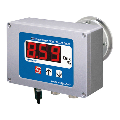
ATAGO CM-BASEa(A) User manual

1
CONTENTS
1. Precautions for Use................................................................................................................................................... 2
2. Refractive Index and Brix....................................................................................................................................... 7
(1) What is refractometer?.................................................................................................................................... 7
(2) What is the Refractive Index?..................................................................................................................... 7
(3) Brix(%) scale ........................................................................................................................................................ 7
(4) Temperature correction................................................................................................................................... 7
3. Unpacking and Installation..................................................................................................................................... 8
(1) Unpacking.............................................................................................................................................................. 8
(2) Installation.............................................................................................................................................................. 8
4. Names and Functions of Components............................................................................................................ 9
5. Mounting the Main Unit to the Bracket or Stand ..........................................................................................10
6. Mounting the Sample Inlet Unit.........................................................................................................................11
7. External Output..........................................................................................................................................................13
(1) CM-BASEα(A)....................................................................................................................................................13
(2) CM-BASEα(D) ...................................................................................................................................................13
8. Power Supply..............................................................................................................................................................17
9. Measuring Brix(%)....................................................................................................................................................18
10. Zero-setting..................................................................................................................................................................19
11. Bias Adjustment.........................................................................................................................................................20
12. Error and Display Lamp.........................................................................................................................................21
(1) During measurement (including when the power is turned on)...............................................21
(2) During zero-setting..........................................................................................................................................21
(3) During measurement or zero-setting.....................................................................................................21
13. Cleaning the Prism...................................................................................................................................................22
14. Consumable Parts and Optional Items .........................................................................................................23
(1) Consumable Parts...........................................................................................................................................23
(2) Optional Items....................................................................................................................................................23
15. Relationships between Brix(%) Values and Refractive Index (nD) Values ................................24
16. Specifications..............................................................................................................................................................25
17. Repair Service and Warranty Period..............................................................................................................26
18. ATAGO CO.,LTD. Service Centers..................................................................................................................27

2
1. Precautions for Use
Introduction
Thank you for purchasing the CM-BASEα In-line Refractometer. Before using your
CM-BASEα, read this instruction manual carefully, and keep it on hand for future reference.
For safe use --- Be sure to observe the following.
To prevent injury and damage to property, safely operate the CM-BASEα by observing the
precautions outlined in this manual. The explanation of the indications and symbols of the
precautions are as follows. Read and understand them before continuing on to the following
pages.
Explanation of indications
WARNING
If this indication is neglected and the instrument is handled
incorrectly, serious injury or death may result.
CAUTION
If this indication is neglected and the instrument is handled
incorrectly, injury and/or property damage may result.
Explanation of symbols
This symbol denotes an item of which to be warned or cautioned.
The contents of warning are described in detail in or near the △.
This symbol denotes an action that must not be performed (a prohibited item).
The contents of prohibition are described in detail in or near the ○.
This symbol denotes an action that must be performed.
The contents of instruction are described in detail in or near the ●.

3
Handling of this instrument
WARNING
◇When measuring a substance harmful to
the human body, be aware of its
properties and wear protective gloves,
mask, etc.
◇Immediately turn off the power (DC24V) if
the unit begins to overheat, smoke or emit
an abnormal smell. Fire or malfunction
may result if the instrument continues to
be used. Contact your ATAGO Distributor
for an inspection.
◇Do not attempt to repair, modify, or
disassemble the instrument yourself.
Improper servicing may result in fire,
electrical shock, or burns.
◇If the instrument is dropped or is
subjected to a strong shock, have it
inspected by an Authorized ATAGO
Service Center.
Fire or malfunction may result if the
instrument is used.
CAUTION
◇Do not apply water or sample to any part
of the instrument other than the surface of
the prism.
Applying water to any other part of the
instrument may result in a malfunction.
◇Do not measure very hot or highly acidic
samples. This may damage the prism,
which would result in inaccurate
measurements.

5
Handling of plug
WARNING
◇Supply the CM-BASEα with DC24V only
(allowable fluctuation is ±10 %).
Short-circuit, smoke, or fire may occur if
other voltages are used.
◇Do not use a power cable that is
damaged, cut, broken, or altered. Use
may result in fire, electrical shock, or
burn.
For repair service of the power cable,
contact an Authorized ATAGO Service
Center.
CAUTION
◇Do not insert or pull out the connector and
plug with wet hands.
Connection of optional component
WARNING
◇Turn off the power (DC24V) prior to
connecting cables to the individual units.

6
Conditions to be observed when using
Environmental conditions
◇Use the instrument at an altitude below 5,000m (above sea level).
◇Use the instrument indoors.
◇Use the instrument where the temperature is between 5 to 40˚C.
◇Do not leave the instrument in a location exposed to direct sunlight or near a heating unit
where the temperature may rise.
◇Do not change the environmental temperature of the instrument suddenly.
◇Do not place the instrument in a place where it may be subject to strong vibrations.
◇Do not use the instrument where there is much dust.
◇Do not leave the instrument where the temperature is extremely low.
◇Do not leave the instrument in a damp place.
◇Do not place or drop heavy objects on the instrument.
◇Use this instrument under the condition where humidity is 80% at 31˚C or lower, falling
linearly to 50% at 40˚C.
◇Main supply voltage fluctuation should not to exceed ±10% the nominal voltage.
◇Installation categories (Overvoltage Categories): ll
◇The pollution degree is 2 (according to IEC60664).
Handling
◇Do not drop the instrument or subject it to any strong shock.
◇The power cable may be damaged by:
Bending the cable.
Pulling the cable.
Twisting the cable.
Placing the cable under heavy objects.
Catching the cable between objects.
Daily maintenance
◇If the instrument becomes dirty, wipe it with a soft cloth.
◇Do not use benzine, paint thinner, etc. to clean the instrument.

7
2. Refractive Index and Brix
The In-line Refractometer CM-BASEα is a refractometer that detects the Refractive Index of
a sample and outputs the Brix(%) value on the display.
(1) What is refractometer?
When a straw is placed into a glass filled with water, the straw appears to bend. When a
straw is placed into a glass filled with sugar water, the straw appears to bend much more
sharply than in the case of water alone. This phenomenon is known as the refraction of
light. The refractometer is an instrument that measures the Refractive Index by utilizing
this principle (the Refractive Index increases in proportion to the concentration of the
solution), and was developed by Dr. Ernst Abbe at the end of the 19th century.
(2) What is the Refractive Index?
If the Refractive Index of air under atmospheric
pressure is 1, then when light enters medium x, the
ratio of the sine of the incident angle <alpha>
measured against the phase boundary to the sine of
the refracting angle <beta> is called the Refractive
Index of the medium x.
The Refractive Index varies with the wavelength of
light and temperature and is represented as follows:
For example, Refractive Index of water at 20˚C under the D-line is:
= 1.33299 (Generally expressed as nD = 1.33299.)
m The Refractive Index is based upon the supposition that the Refractive Index in a
vacuum is 1 and is called the absolute Refractive Index. Generally, however, this index
is seldom used.
(3) Brix(%) scale
The CM-BASEα is programmed with the Brix(%) scale, based on the Refractive Index of
water (nD = 1.33299) as the reference (0%). The Brix(%) scale represents the weight of
sucrose expressed by percentage (sucrose weight in grams contained in 100 grams of
sucrose solution). Therefore, this scale corresponds with the sucrose concentration. For
samples such as water-soluble cutting oil, it is possible to create a conversion table in
advance to show the relation between the sample’s concentration % and Brix %, and
convert the Brix measurement value into its concentration. However, it is very common to
create a concentration standard using Brix values, and monitor with Brix values in
everyday operations.
C The relationship between Brix(%) and the Refractive Index (nD) is outlined on
page 24.
(4) Temperature correction
The Refractive Index of a substance varies with temperature. Thus, when using a refractometer
to measure the Refractive Index of a liquid, the measurement value will vary with the sample
temperature.
The CM-BASEα always detects the prism temperature. The value of the measurement is
automatically corrected for temperature by a built-in processor, so that the displayed value is
equal to the value measured at 20˚C (provided that the sample temperature is within the range of
10 to 50˚C).
n: Represents the Refractive Index
t: Temperature (˚C)
D: D-line of natrium (589nm)

8
3. Unpacking and Installation
(1) Unpacking
①Unpack the CM-BASEα and confirm that there is no external damage.
②Check that the following items are included.
CM-BASEα(A) Cat.No. 3603
Main unit ..................................................... 1
Power and Recorder output cable ............... 1
O-ring (Silicon) ............................................ 1
O-ring (EPDM) ............................................ 1
Bracket
Instruction manual (this book) ..................... 1
Inspection certificate ................................... 1
CM-BASEα(D) Cat.No. 3604
Main unit ..................................................... 1
Power and RS-232C cable .......................... 1
O-ring (Silicon) ............................................ 1
O-ring (EPDM) ............................................ 1
Bracket
Instruction manual (this book) ..................... 1
Inspection certificate ................................... 1
(2) Installation
WARNING
◇Do not supply power (DC24V) until cable connection has been
established.
①The CM-BASEα should be supplied with DC24V (allowable fluctuation is ±10%).
②The CM-BASEα should be installed in a location with an ambient temperature of 5 to
40 ˚C.
③Because the CM-BASEα incorporates highly precise components, DO NOT install in
locations exposed to direct sunlight or near a heating source, or in an environment
that is dusty or exposed to corrosive gasses.
④The CM-BASEα should be installed in a location that is free from vibration. When
installing, take special care to avoid any strong shock to the instrument.
⑤Do not touch the prism surface with your hand. Finger-prints left on the prism surface
may cause sample to build up on the prism.
In the event of contact with the prism surface, clean carefully with a soft tissue soaked
with ethyl alcohol.
In order to prevent scratches, never clean the prism surface using abrasive materials.

9
4. Names and Functions of Components
①Liquid Crystal Display (LCD)
Displays the measured values.
②ZERO key
Press to perform zero-setting.
③Indicator Lamp (Green)
The light flashes during zero-setting,
and stays lit during measurement.
④Indicator Lamp (Red)
The light comes on/flashes when an
error occurs.
⑤Screw mounting holes
Used to mount the main unit to the
bracket, stand (optional), etc.
⑥Connector
Terminal to connect the power
(DC24V) and output cable.
⑦Prism
Corrosion resistant optical glass, with
a polished surface to reflect light.
⑧Prism stage
Connected to the sample inlet and
fastened by a clamp band.
⑥
③
④
①
⑧
⑦
②
⑤
⑤

10
5. Mounting the Main Unit to the Bracket or Stand
WARNING
◇Turn off the power (DC24V) before mounting.
Electrical shock may occur if the unit is mounted with the power
(DC24V) connected.
Screw mounting holes (Fig. 5-1)
The main unit have four mounting screw holes.
Use the mounting screw holes to mount the
main unit to the bracket (included), stand
(optional), etc.
Fig. 5-1
Screw mounting example (Fig. 5-2)
①Main unit
②Bracket
③Washer (M4)
④Socket head cap screw with spring washer
M4x8
NWashers (M4) and socket head cap
screws with spring washers M4x8 are
included with the bracket.
Fig. 5-2
Main unit mounted to the bracket or stand (optional) (Fig. 5-3,Fig. 5-4)
Fig. 5-3
Fig. 5-4
Install the bracket with the main unit to
the device, tank, etc.
mInstall the bracket so that the
prism surface of the main unit is at
a right angle to the ground.
CFor information on ordering the
stand (optional ), see page 23
"14.Consumable Parts and
Optional Items".
①
②
③
④
Stand
Mounting
screw
hole
Mounting
screw
hole
Bracket

11
6. Mounting the Sample Inlet Unit
WARNING
◇Turn off the power (DC24V) before mounting. Electrical shock
may occur if the unit is mounted with the power connected.
CAUTION
◇Ensure that the prism is clean and free of any damage and/or
scratches. Completely remove any sample before installing the
CM-BASEα to piping or equipment.
When installing the CM-BASEα, be sure to note the following points.
①The size of the prism stage of the CM-BASEα is a 3S ferrule.
②Install the CM-BASEα so that the prism surface is at a right angle to the ground.
③Connect the unit to the piping so that the sample flow directly contacts the prism
surface. The direct flow of samples (and self cleaning solutions) in contact with the
prism will keep substances from adhering to the prism surface.
④The sample solution must remain in the temperature range of 10 to 50 ˚C.
⑤During operation, build up of solids, dirt and/or grease may form on the prism surface.
When this occurs, the prism surface must be manually cleaned (See page 22.). For
ease of cleaning, the CM-BASEα should be installed in such a manner so that the unit
can be easily removed from the piping or solution tank.
Sample inlet units are available as pipe fittings: straight type and L type.
The straight type should be installed on straight sections of piping. The L type inlet
should serve as the joining piece for piping intended to align in an L shape.
There are three ways to connect a sample inlet to a pipe: IDF/ISO clamp union (ferrule),
IDF/ISO screw union (screw), and JIS Flange.
Other sample inlets available include small diameter series compression fitting (outer
diameter 10mmφ) and hose connector (outer diameter 12mmφ).
Straight type
L type
Compression Fitting
Hose Connector

12
Mounting procedure (Fig. 6-1, Fig. 6-2, and Fig. 6-3)
①Install the CM-BASEα so that the prism surface is at a right angle to the ground.
②Attach the sample inlet unit to the CM-BASEα with O-ring inserted between them, and
fasten them together with the clamp band.
③Install the inlet unit so that the sample solution runs from the lower nozzle to the upper
nozzle to prevent air bubbles from forming.
④When connecting the tubes to the hose connector, clamp them with a tie band. The tie
bands provided with the hose connector are made of plastic. If chemicals corrosive to
plastics are used, substitute with tie bands made of other material.
⑤The prism surface may become contaminated with solids, dirt and/or grease. If this
happens, the prism surface must be cleaned by hand. (See page 22.) The sample
inlet unit should be installed in such a manner that it can be easily removed to allow
access to the prism for cleaning.
Fig. 6-1
Fig. 6-2
Fig. 6-3
Dimensions
Prism stage
O-ring (silicon
or EPDM)
Bottom
Top
Flow of solution
Flow of solution
Prism stage
O-ring
(silicon or EPDM)
Sample inlet
unit
(optional)
ex.hose connector
Clamp band

13
7. External Output
WARNING
◇Turn off the power (DC24V) when connecting the cable from the
terminal.
The CM-BASEα(A) transmits data via 4-20mA signals. The CM-BASEα(D) transmits data
to a computer via RS-232C.
(1) CM-BASEα(A)
The provided cable connects to the base of the CM-BASEα(A), and it provides power
(DC24V) to the instrument and transmits Brix data via DC 4-20mA. Brix values ranging
from -2.0 to 33.5% are communicated as DC ranging from 4 to 20mA respectively.
Connector pin number
Code color
Signal name
1
Red
DC24V
2
Black / White
DC4 to 20mA GND
3
Black
DC24V GND
4
Red / White
DC4 to 20mA
(2) CM-BASEα(D)
The provided cable connects to the base of the CM-BASEα(D), and it provides power
(DC24V) to the instrument and transmits Brix and temperature data via RS-232C.
Connector pin number
Code color
Signal name
1
Red
DC24V
2
Black / White
RS-232C GND
3
Black
DC24VGND
4
Red / White
RS-232C
Communication parameters
BAUDRATE : 2400bps
DATA LENGTH: 7bit
PARITY : Even
STOP BIT : 1bit
Transmit data
aa.a,bb.b
aa.a represents Brix value. The Brix display range is
"-2.0 to 33.5".
When Brix value is less than -2.1, LL.L will be
displayed.
When Brix value is more than 33.6, HH.H will be
displayed.
bb.b represents temperature.
3
4
1
2
3
4
1
2

14
Computer Output
①Computer - Data Setting
Download a terminal emulator for PC serial communication.
Here, the open-source software “Tera Tarm” is used as an example.
Download Tera Term from a website, such as the one below:
https://ttssh2.osdn.jp/index.html.en
(1)Start Tera Term.
Select "serial" on the New connection dialogbox.
Select the port number.
Click OK.
※Check the port number.
"Control Panel" "System and Security" "Device Manager" "Port"
(2)Click Setup, and then Serial port.

15
(3)The serial settings are conformed to the instrument settings.
Enter the port number selected in step (1).
Click OK.
(4)Click Setup, and then Terminal port.
(5)Enter the settings as shown below and Click OK.

16
②Data Output From Main Unit to PC
Every time a measurement is taken, a new row of data appears in the Tera Term
window.
Fixed range (No zero suppression) : ○○.○,△△.△CR / LF
○○.○: Brix(%)
The Brix(%) output range is "-2.0 to 33.5".
Example
Output Data
Brix(%)
6.3
6.3
25.0
25.0
LL.L
-2.1 or less
HH.H
33.6 or higher
△△.△: Temperature
Example
Output Data
Temperature(˚C)
9.5
9.5˚C
23.5
23.5˚C

17
8. Power Supply
WARNING
◇NEVER connect the CM-BASEα to power other than DC24V
(allowable fluctuation is ±10%).
◇NEVER use a power cable that is damaged, cut, broken, or
altered. Fire, electrical shock or burns may occur.
To purchase replacement power cables, contact an Authorized
ATAGO Distributor.
①Make sure that the cable is properly connected to the port.
②Once the power (DC24V) is turned on to the instrument, either the green light or red
light will come on.
m The CM-BASEα has no power switch. When power (DC24V) is supplied to the
CM-BASEα, the measurement value display illuminates and the Brix(%)
measurement commences.
The green light comes on when a sufficient amount of liquid with a Brix value of -2.0 to
33.5% is passing by the prism. When there is not enough liquid passing by, the red light
turns on and error message "LLL" is displayed. When the Brix of the liquid is above
33.6% or more, the red light turns on and "HHH" is displayed.

18
9. Measuring Brix(%)
CAUTION
◇DO NOT measure any sample that can damage the prism or the
sample inlet unit. Sample temperature should be kept between
10˚C and 50˚C when the power (DC24V) is turned on.
◇If the sample solution could potentially stain the prism,
immediately clean the prism after measurement (following the
instructions on page 22 of this instruction manual).
①When power (DC24V) is supplied to the CM-BASEα, the Brix(%) measurement starts.
(*) The CM-BASEα has no power switch.
②The Brix(%) value will be displayed when sample flows onto the prism surface.
(*) CM-BASEα(D) also outputs temperature as well.
③If there is no sample on the prism surface (only air), the red light is on and the error
message LLL will be displayed.
External output relationship is shown in the table below.
mSee page 21 if the red light is on even though the prism surface is sufficiently
covered with liquid.
④The CM-BASEα constantly detects the temperature of the prism. When the sample
temperature is within the range of 10 to 50˚C, the Brix(%) values are automatically
compensated for temperature.
mA left arrow will appear on the screen when the sample temperature is 9.4˚C or
less, or 50.6˚C or more. The Brix values displayed while the arrow is displayed
are not properly temperature-compensated.
⑤For calibration (zero-setting) see page 19.
CM-BASEα(A)
CM-BASEα(D)
Brix
Display
Indicator Lamp
DC
Brix
Display
Indicator Lamp
RS-232C
-2.1% or less
LLL
Red
4mA
-2.1% or less
LLL
Red
LL.L
-2.0 to 33.5%
Measured value
Green
4 to 20mA
-2.0 to 33.5%
Measured value
Green
Measured value
33.6% or more
HHH
Red
20mA
33.6% or more
HHH
Red
HH.H
Temperature
Display
Indicator Lamp
DC
Temperature
Display
Indicator Lamp
RS-232C
9.4℃or less
”←” Lighting
Red & Green
-
9.4℃or less
”←” Lighting
Red & Green
Measured Temperature
9.5 to 50.5℃
-
Green
-
9.5 to 50.5℃
-
Green
Measured Temperature
50.6℃or more
”←” Lighting
Red & Green
-
50.6℃or more
”←” Lighting
Red & Green
Measured Temperature

19
10.Zero-setting
mBefore zero-setting, confirm that the prism surface is clean.
①Confirm that the sample inlet unit is properly connected to the piping.
②Let tap water flow through the piping.
③Supply power (DC24V) to the CM-BASEα referring to the procedure described in
Chapter 7. "Power Supply" on page 14.
Green light is illuminated.
④The current measurement is displayed and output.
(*) Also output temperature CM-BASEα(D).
⑤Press the ZERO key.
⑥The green light and “000” on the LCD will flash three times.
Once zero-setting is complete, the green light will remain lit and it will start taking the
measurements again.
mIf zero-setting is not successfully completed, the red light will flash and “AAA”
will display on the LCD. Pressing the ZERO key once more will turn off the red
light and will restart taking measurements. Turn off the power (DC24V), clean
the prism, and try zero-setting again with an ample amount of tap water.

20
11.Bias Adjustment
The bias adjustment feature allows the instrument to display readings that have been
adjusted by a fixed value added or subtracted from the actual measured value.
Hold down the ZERO key for approximately 5 seconds to activate the TEST mode, and the
displayed value will start flashing.
The displayed value increases by 0.1 each time the ZERO key is pressed.
The value can only increase, not decrease.
Continue to press the ZERO key until the maximum value of +2.0 is reached, and then, it will
become -2.0 next. From then on, the value increases from -2.0 by 0.1.
Example:
Displaying 10.0% as 10.5%
Hold down the Zero key.
Flashing
Press the ZERO key to add
0.1 each time.
Hold down the ZERO key.
Confirm
A bias setting is retained until subsequent zero-setting, and it will be reset at that time.
Recording the bias setting is highly recommended.
10.2
10.5
10.5
10.1
10.0
10.0
This manual suits for next models
3
Table of contents
Other ATAGO Monitor manuals

