ATB HBA-008 Manual

Innovations for clean water
ATB – HBA(-C)
Installation/Operating Instructions

Installation/Operating Instructions ATB – HBA(-C)
ATB WATER GmbH, Südstraße 2, 32457 Porta Westfalica, Germany, www.atbwater.com
Version: 01.04.2022 / Page 2 of 30
!!! IMPORTANT !!!
PRIOR TO USING THE UNIT
•Anybody involved MUST imperatively read and fully understand the unit’s O&M manual.
•It is most important that the O&M manuals remain with the operator for future reference.
GENERAL
•No foreign objects such as hard materials, plastic bags, etc... are allowed in the basins.
These objects can cause extensive damage and/or for example create unbalances to
the impeller.
PLEASE NOTE:
•The following information refers to the standard execution of the aerators. In the case of
special versions, which can be identified as such by the product designation, deviations
may occur. If necessary, this manual can be supplemented with additional information.
•As our products are subject to continuous development, the technical specifications in
the tables are to be regarded as non-binding. ATB Water reserves the right to introduce
technical changes to its products without prior notice.
•Failure to comply with the information contained in these documents, misuse or
unauthorized alteration of the product will void the warranty.

Installation/Operating Instructions ATB – HBA(-C)
ATB WATER GmbH, Südstraße 2, 32457 Porta Westfalica, Germany, www.atbwater.com
Version: 01.04.2022 / Page 3 of 30
Content
1. Safety regulations............................................................................................................................ 4
2. Product overview............................................................................................................................. 5
2.1. Description............................................................................................................................. 5
2.2. Working principle.................................................................................................................... 6
2.3. Exclusion of fields of application............................................................................................. 6
3. Receiving and handling................................................................................................................... 7
3.1. Receiving and acceptance ..................................................................................................... 7
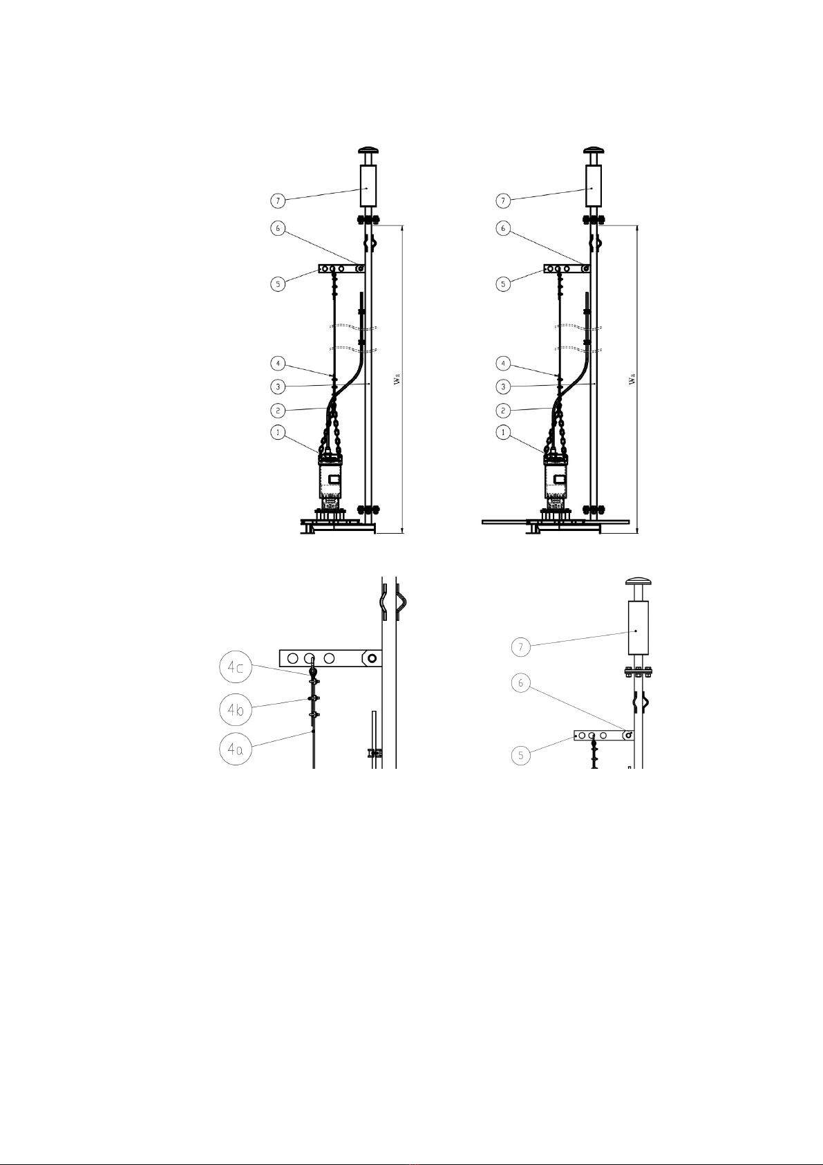
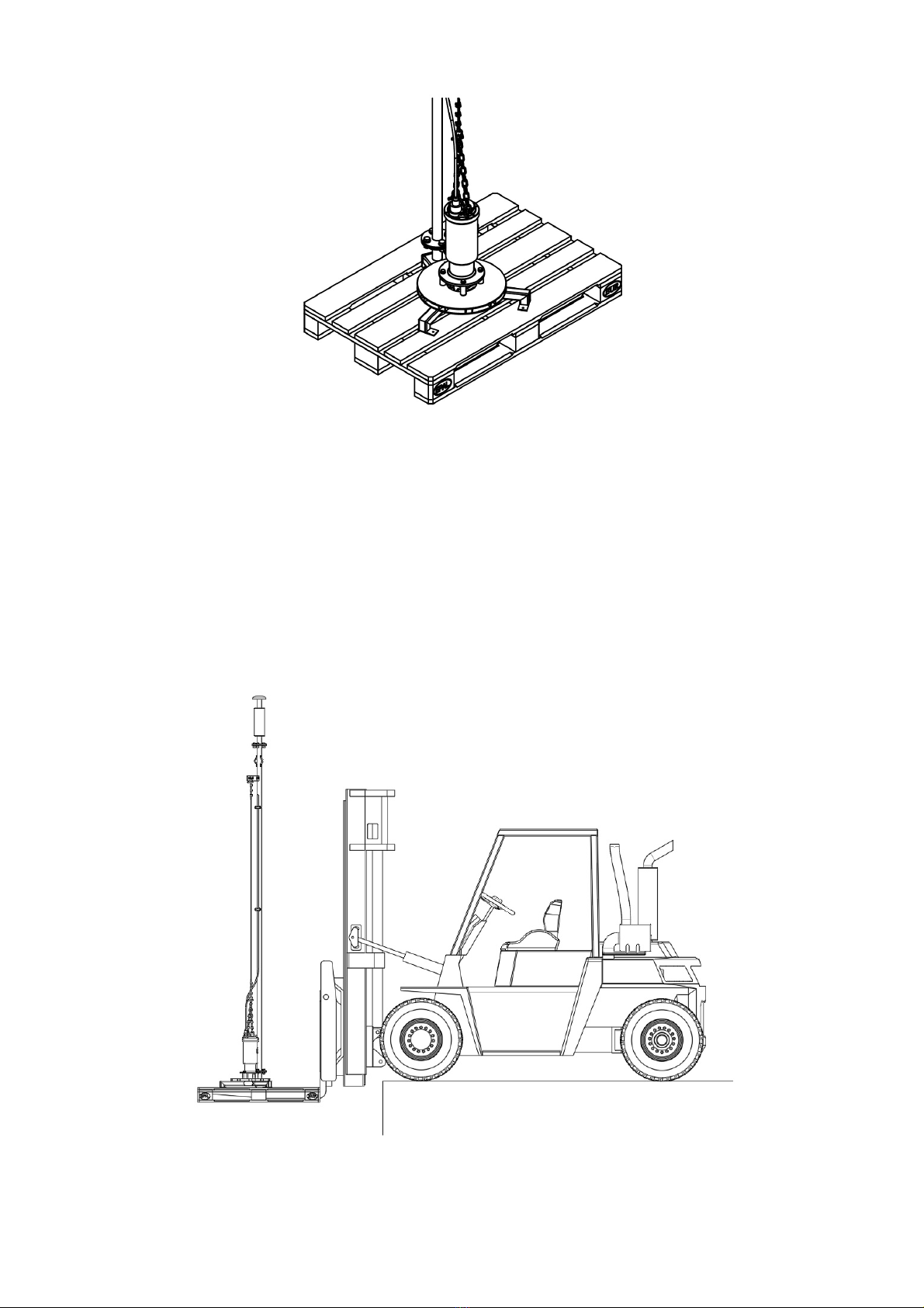
3.2. Handling (loading/unloading).................................................................................................. 7
4. Assembly........................................................................................................................................ 10
4.1. Preliminary work / instructions / installation of the aerator .....................................................10
4.2. Assembly and installation......................................................................................................11
4.2.1. Mounting the extension channels (HBA-C only) ..............................................................11
4.2.2. Mounting the intake pipe and the silencer (optional)........................................................11
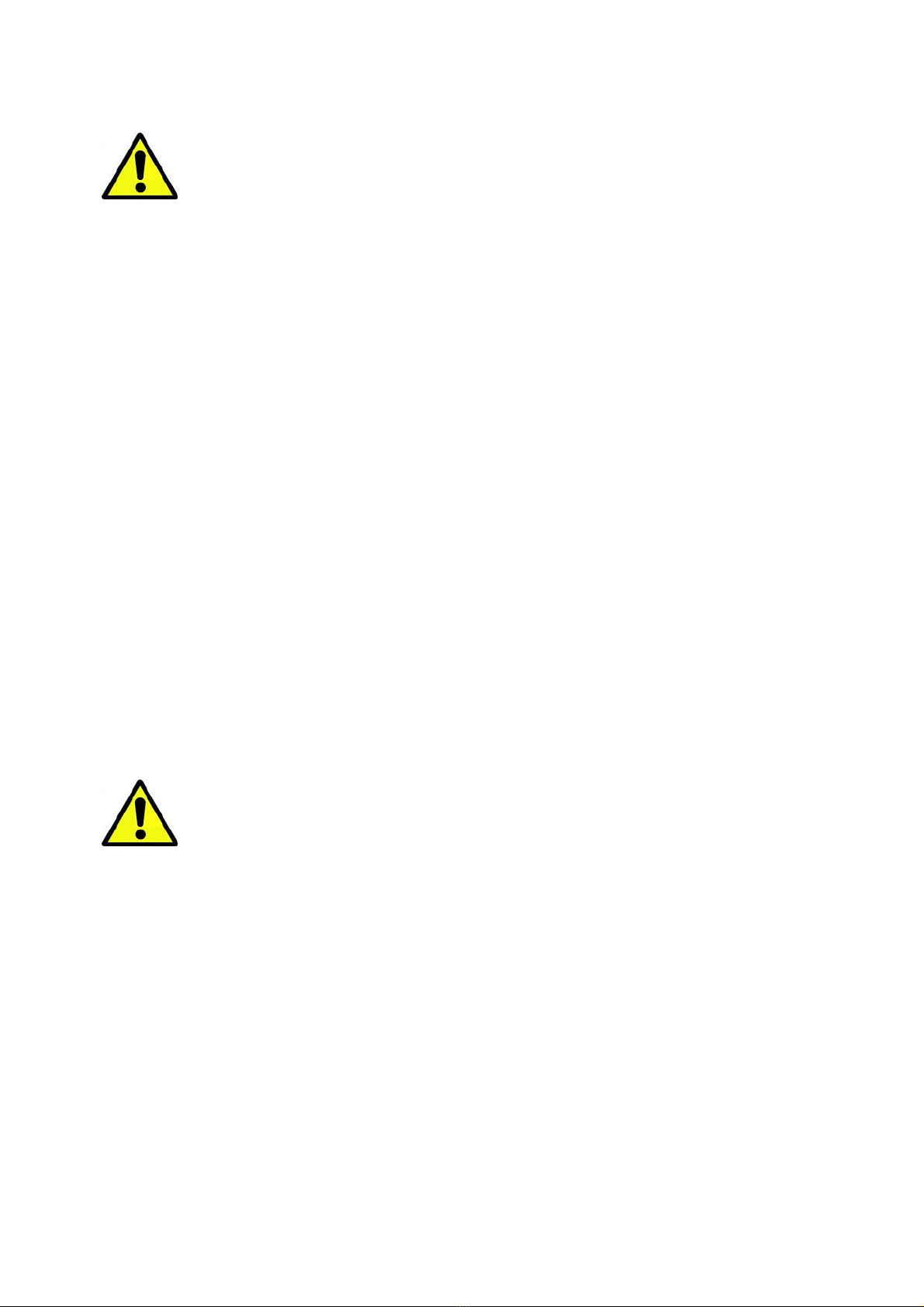
4.2.3. Assembly of the lifting device supplied by ATB (optional)................................................11
4.2.4. Installation of the power cable .........................................................................................13
4.2.5. Installation of the aerator in the tank................................................................................13
4.3. Instructions for electrical connection......................................................................................14
4.3.1. General instructions ........................................................................................................14
4.3.2. Control panel...................................................................................................................15
4.3.3. Direction of rotation .........................................................................................................16
4.3.4. Delta connection..............................................................................................................17
4.3.5. Star connection ...............................................................................................................17
4.4. Start-up .................................................................................................................................18
5. Operation and maintenance.......................................................................................................... 19
5.1. Operation ..............................................................................................................................19
5.2. Maintenance .........................................................................................................................19
5.2.1. Leakage test....................................................................................................................20
5.2.2. Oil check ........................................................................................................................21
5.2.3. General overhaul.............................................................................................................22
5.2.4. Checking the insulation of the motor................................................................................22
5.2.5. Lubrication.......................................................................................................................23
5.2.6. Checking the impeller......................................................................................................23
5.2.7. Checking the air intake....................................................................................................23
ENCLOSURE I: General data ............................................................................................................ 27
ENCLOSURE II: Declaration of conformity...................................................................................... 28
ENCLOSURE III: Maintenance sheet ................................................................................................ 29
ENCLOSURE IV: O&M manual of the motor.................................................................................... 30

Installation/Operating Instructions ATB – HBA(-C)
ATB WATER GmbH, Südstraße 2, 32457 Porta Westfalica, Germany, www.atbwater.com
Version: 01.04.2022 / Page 4 of 30
1. Safety regulations
We will mention, in this chapter, the major kind of risks and dangers that might
occur and the safety precautions to be taken.
•As mentioned in our declaration of conformity, our submerged aerator can only be used
when the installation, into which it needs to be incorporated, is declared conform to the
Machinery Directive.
•Devices with motors without explosion protection must never be operated in basins with
explosive media.
•Unauthorized personnel must leave the working area of the unit!
•The installation, maintenance, repair or dismantling of the device must be carried out by
qualified personnel who have the appropriate qualifications and are equipped with suitable
tools. Operation may also be carried out by non-specialised personnel provided that they
are fully familiar with the contents of this manual and all other documents supplied with the
product.
•All electrical parts must be installed and connected in accordance with the European
Standard EN 60204 for the electrical equipment of machines.
•During the installation of the device in the tank, individual steps must be taken to protect the
personnel. This applies in particular to the use of suitable protective clothing. In principle, all
applicable accident prevention regulations must be observed. Specifically make sure that
the oxygen concentration is sufficient and that no toxic gases are present in the working
area.
•Before welding or using an electric tool, make sure that there is no risk of explosion.
When working on the electrical system or during maintenance and repair works, it
must be ensured that the circuit breaker is switched off and locked.
•Suitable safety measures must be taken at all times to ensure that no person can fall into
the water.
•A second person must be involved in all works on the electrical system or maintenance and
repair works.
•For safety reasons, but also to avoid exclusion of warranty, the aerator must not be
operated in the event of faults or changes in performance.
ATB WATER GmbH is not responsible for any kind of incidents.

Installation/Operating Instructions ATB – HBA(-C)
ATB WATER GmbH, Südstraße 2, 32457 Porta Westfalica, Germany, www.atbwater.com
Version: 01.04.2022 / Page 5 of 30
2. Product overview
2.1. Description
Drawing 1: Type HBA (left) and HBA-C (right)
Drawing 2: Cable and clamps (left) and lifting bracket (right)
Legend for drawings 1 and 2:
1 = Fixation zone of the motor chain
2 = Electric cable or cables
3 = Intake pipe
4 = Lifting kit
4.a = Rope
4.b = Clips
4.c = Thimble
5 = Lifting bracket
6 = Plate for fixing the lifting bracket
7 = Silencer

Installation/Operating Instructions ATB – HBA(-C)
ATB WATER GmbH, Südstraße 2, 32457 Porta Westfalica, Germany, www.atbwater.com
Version: 01.04.2022 / Page 6 of 30
2.2. Working principle
The submersible aerators type HBA and HBA-C consist of a submersible motor, which drives an
impeller. The rotation of the impeller creates a vacuum inside the unit, which draws air into a
suction chamber. The air and the liquid are mixed in the chamber and pushed into the ejection
channels and ejected with a radial discharge, whereby the medium in the tank is aerated and
mixed.
The electric motor is a submerged three-phase asynchronous cage motor with IP68 degree of
protection, insulation class F or H, suitable for continuous operation (S1).
Starting from type HBA-040 and for all larger devices the motor will be equipped with the
following protection devices:
•Thermal protection devices
•Electrode to detect water in the oil chamber.
Smaller motors up to 3 kW can be optional (on demand) equipped with thermal protection devices
while oil leakage sensors are not available.
The aerators can be installed without the aid of any anchoring and supporting structure. The
machine's own weight and low centre of gravity generally ensures high stability. Under special
operating conditions, however, the aerator could eventually start to move. In such cases, the intake
pipe is anchored to the pool edges with 3 ropes to fix the aerator (see Drawing 5).
A lifting cable, which can be attached to the engine and intake pipe, allows easy removal and
repositioning of the aerators without the use of operating bridges or platforms or emptying the tank.
2.3. Exclusion of fields of application
The aerators of the HBA and HBA-C series are generally not suitable for the following applications
or operating conditions:
•Dry operation or operation in which the motor with the liquid to be aerated is not completely
submerged;
•Aeration/mixing of liquids with a temperature exceeding 40°C;
•Water depth exceeding the highest values in table 1;
•pH value of the liquid to be aerated/mixed outside the range 6 to 8.5 (if other pH values are
required, special versions can be manufactured according to customer requirements);
•Aeration/mixing of flammable liquids;
•Operation in potentially explosive atmospheres.

Installation/Operating Instructions ATB – HBA(-C)
ATB WATER GmbH, Südstraße 2, 32457 Porta Westfalica, Germany, www.atbwater.com
Version: 01.04.2022 / Page 7 of 30
3. Receiving and handling
3.1. Receiving and acceptance
Check the goods for completeness and visible damage before unloading.
Any damage caused during transport must be reported immediately. The scope of delivery must be
compared with the information on the delivery note. Before confirming receipt of the delivery by
signature, the relevant remarks must be noted.
In the event of damage or the discovery of missing or incorrect accessories, ATB must be notified
immediately in writing.
3.2. Handling (loading/unloading)
Be careful when handling this type of heavy, precision equipment to avoid damage to it or other
equipment, or injure any person involved. Persons that are not directly involved in
loading/unloading should be kept out of the handling area.
The lifting equipment used should have been inspected and approved by an official authority prior
to unloading the truck in order to allow safe handling.
The eyebolts or the handle for lifting the aerator are located on the upper part of the motor. The centre
of gravity of the aerator without intake pipe is close to the vertical axis due to the radial geometry of
the aerator. Due to the design of the unit, the centre of gravity is in the lower part of the unit. When the
intake pipe is mounted, the centre of gravity of the aerator is placed in the direction of the intake pipe
but remains between the eyebolts.
When handling the aerator, a distinction must be made between 3 cases:
1. dispatch and acceptance of the unit
2. handling with intake pipe and non-mounted extended channels (if fitted), i.e. moving the
aerator on the premises of the treatment plant;
3. handling with intake pipe and already mounted extended channels (if any), i.e. moving the
aerator for installation in the tank.
Case 1:
During shipment and acceptance, the aerator must be placed on a pallet with an appropriate load
capacity. It must be protected with a packaging foil or packed in a wooden box.
The aerator is supplied with two iron brackets attached to the pallet (see Drawing 3).
To separate the aerator from the pallet, remove the screw connecting each bracket to the aerator foot.
Finally, remove the mounting brackets from the pallet by removing the mounting screws. Keep the
mounting brackets in case the aerator will have to be transported again in the future.

Installation/Operating Instructions ATB – HBA(-C)
ATB WATER GmbH, Südstraße 2, 32457 Porta Westfalica, Germany, www.atbwater.com
Version: 01.04.2022 / Page 8 of 30
Drawing 3: Removal of the device fastenings on the pallet
Case 2:
If you lift and move the aerator inside the wastewater treatment plant, use the special handle to move
it with sufficient force for the weight of the unit without accessories and lifting gear. When handling
with forklift trucks, position the forks parallel to the suction chamber and take care not to crush or
break the chamber itself (see Drawing 4). Always place the aerator on a firm surface with applicable
load-bearing capacity.
Check the weights and dimensions of the aerator.
Drawing 4: Handling on the wastewater treatment plant

Installation/Operating Instructions ATB – HBA(-C)
ATB WATER GmbH, Südstraße 2, 32457 Porta Westfalica, Germany, www.atbwater.com
Version: 01.04.2022 / Page 9 of 30
Case 3:
For handling during installation of the aerator in the tank, all accessories required for operation
must already be installed (see below). The entire unit must then be lifted by means of a crane with
the appropriate lifting capacity.
While lifting the aerator with the intake pipe fitted, the unit may sway slightly. However, it is
impossible for the unit to tip over. The use of the sling bar (see Drawing 2) minimises the
inclination of the assembly aerator + intake pipe unit when particularly long intake pipes are
present.
Take care not to damage the electrical cable when moving the device. It is
explicitly forbidden to pull the device by the electric cable!
Do not bend the cable (bending radius > 5 times cable diameter). The open cable end must never
get into contact with water and must be protected from weather influences.

Installation/Operating Instructions ATB – HBA(-C)
ATB WATER GmbH, Südstraße 2, 32457 Porta Westfalica, Germany, www.atbwater.com
Version: 01.04.2022 / Page 10 of 30
4. Assembly
4.1. Preliminary work / instructions / installation of the aerator
For safety reasons, the device must always be installed by at least 2 persons.
•Make sure that the aerator has not been damaged during transport.
•Check the horizontal orientation of the aerator's footprint. The aerator should be installed as
vertically as possible. Using the aerator in a non-vertical position could cause considerable
damage to the rotating parts.
•Do not immerse the end of the cable. In addition, the aerator must never be lowered by
means of the electric cable, but only by means of the steel cable provided for this purpose.
Such unauthorized actions could cause water to enter the cable, break the inner conductors
or damage the motor.
•Only qualified personnel may extend the power cable if necessary.
•The water depth has a considerable influence on the operating conditions of the motor. The
bigger the water depth, the higher will be the load on the motor.
•The maximum water depth indicated in table 1 must not be exceeded under any
circumstances. However, after consultation with ATB, deviations are possible, and ATB will
adapt the aerator accordingly.
Aerator Power Maximum
Water Depth
Type [kW] [m]
HBA-008 0,8 2,50
HBA-015 (-C) 1,5 2,50
HBA-030 (-C) 3,15 3,50
HBA-040 (-C) 4,0 3,50
HBA-055 (-C) 5,5 5,00
HBA-075 (-C) 7,5 5,00
HBA-090 (-C) 9,0 6,00
HBA-110 (-C) 11,0 6,00
HBA-150 (-C) 15,0 6,50
HBA-185 (-C) 18,5 6,50
HBA-220 (-C) 22,0 6,50
HBA-300 (-C) 30,0 7,00
HBA-370 (-C) 37,0 7,00
HBA-450 (-C) 45,0 8,00
HBA-550 (-C) 55,0 8,00
HBA-750 (-C) 75,0 8,00
Table 1: Maximum permitted water depth
•In addition, make sure that the aerator motor is constantly submerged. Otherwise the
motor could overheat and be damaged.

Installation/Operating Instructions ATB – HBA(-C)
ATB WATER GmbH, Südstraße 2, 32457 Porta Westfalica, Germany, www.atbwater.com
Version: 01.04.2022 / Page 11 of 30
•The aerators should preferably be installed in square or round containers. For oblong
rectangular tanks, it is recommended to use several aerators with lower capacity.
Alternatively, additional mixers can be used to avoid partial formation of dead zones.
Before starting to install the unit in the tank, we strongly recommend that you submit an
installation plan to ATB for approval in order to avoid incorrect positioning.
•After a long period of inactivity of the aerator, the oil quantity should be checked.
•When an aerator is put back into operation after a break in operation, it should also be
checked that there are no foreign bodies and/or water in the oil. The emptied oil must be
disposed of in accordance with the applicable regulations.
Before electrically connecting the aerator, check by hand that the impeller is free
to move and rotates easily. Under no circumstances should this check be carried
out when the aerator is connected to a power supply.
•After this check and the installation of the aerator on an appropriate surface, the electrical
and thermal protection devices must be connected by qualified electricians.
If the thermal protection device and the oil chamber control are not or
poorly connected, any warranty claims will be refused.
•Check by inspection the correct direction of rotation of the motor (clockwise in top view).
You should be at least one meter away from moving parts, wear suitable protective clothing
and do not touch the aerator.
4.2. Assembly and installation
4.2.1. Mounting the extension channels (HBA-C only)
The models of the HBA-C series are equipped with extension channels. For transport reasons
these are not assembled for delivery. Before installing an aerator, these channels must be
mounted on the ribs emerging from the plate.
4.2.2. Mounting the intake pipe and the silencer (optional)
Assemble the intake pipe and, if necessary, the silencer using the flange connection provided (for
types up to and including 3 kW engines: screw connection "1 ¼").
4.2.3. Assembly of the lifting device supplied by ATB (optional)
Please note: The numbers used refer to drawing 1 and 2.
•Fit the sling bar (6) to the intake pipe (3) using the collar (7).
For the types with engine up to 3 kW inclusive (i.e. with intake pipe 1 "¼"), the collar is
replaced by two welded ribs.
If correctly installed, the bracket must be foldable upwards
(see arrow in Drawing 2).
•The recommended distance T1 is 200 to 250 mm.
•Provide each end of the rope (5.1) with the supplied clamps (5.2) and thimbles (5.3).

Installation/Operating Instructions ATB – HBA(-C)
ATB WATER GmbH, Südstraße 2, 32457 Porta Westfalica, Germany, www.atbwater.com
Version: 01.04.2022 / Page 12 of 30
•Then attach one end to the aerator handle and the other end to the sling bar.
The clamps should be mounted with the saddle on that part of the rope that is
under tension and the bracket on the other part of the rope. The distance between
2 clamps should be 1.5 to 3 times the width of the clamp (see Drawing 2). Refer to
Table 2 for rope diameter, minimum number of clamps for each end, and
recommended length LR.
•The rope must be mounted in such a way that it is almost tensioned.
A suitable lifting device must be connected to the ring (8) to lift the aerator +
suction pipe unit. The bracket then folds upwards and tensions the pull cable.
If the lifting device supplied by ATB is not used, the customer/installer must
provide an appropriate device with rope or chain. This device must be attached on
one side to the handle of the aerator and on the other side to a point outside the
tank intended for later removal of the aerator. The choice and dimensioning of
such alternative lifting devices are the exclusive responsibility of the
customer/installer.
Aerator Power Rope
diameter
Minimum number of
cl
amps for each end
Recommended
mo
unting
lengt
h
Type [kW] [mm] [mm]
HBA-008 0.8
4 3 220
HBA-015 (-C) 0.15
HBA-030 (-C) 3,15
HBA-040 (-C) 4,0
HBA-055 (-C) 5,5
HBA-075 (-C) 7,5
HBA-090 (-C) 9,0
HBA-110 (-C) 11,0
6 3 300
HBA-150 (-C) 15,0
HBA-185 (-C) 18,5
HBA-220 (-C) 22,0
HBA-300 (-C) 30,0
HBA-370 (-C) 37,0
HBA-450 (-C) 45,0
8 3 350
HBA-550 (-C) 55,0
HBA-750 (-C) 75,0
Table 2: Rope and clamps

Installation/Operating Instructions ATB – HBA(-C)
ATB WATER GmbH, Südstraße 2, 32457 Porta Westfalica, Germany, www.atbwater.com
Version: 01.04.2022 / Page 13 of 30
4.2.4. Installation of the power cable
The power cable must be attached to the intake pipe using the clamps provided.
The cable must not be under tension or bent. Only clamps without cut edges may
be used, or protective devices must be used between the cable and the clamps.
The clamps must not be tightened too much to prevent damage to the cable. The
cable must always be protected from sharp surfaces and/or sharp edges.
4.2.5. Installation of the aerator in the tank
•Simply lower the aerator to the intended position and place it on the bottom of the tank.
•Gently pull out the power cable so that it runs along the shortest route. If necessary, use
floating buoys to hold the cable.
•If there is a risk of the aerator shifting during operation, it is recommended to anchor the
aerator with ropes (see Drawing 5).
Drawing 5: Recommended mooring

Installation/Operating Instructions ATB – HBA(-C)
ATB WATER GmbH, Südstraße 2, 32457 Porta Westfalica, Germany, www.atbwater.com
Version: 01.04.2022 / Page 14 of 30
4.3. Instructions for electrical connection
4.3.1. General instructions
The aerator motor housing must not be opened. However, if this is necessary, such
work may only be carried out by qualified personnel.
The electrical connection may only be carried out by qualified electricians in compliance with all
applicable accident prevention regulations.
The switch cabinet should be protected by RCD (protection against possible insulation damage of the
motor).
The motors are usually operated at 400 V. For other supply voltages, please contact ATB.
Complete the grounding connections using the yellow and green conductor of the power cable. In
case of a double power cable for the star-delta starting, connect to the grounding both yellow and
green conductors.
Check the correct running of the power cable and the signal cable connections.
ATTENTION:
When carrying out tests to check the motor operational conditions, the motor can
work out of the water for no more than ten minutes.
Depending on the device supplied, the motor is connected either directly (DOL) or via star-delta.
If the supply cable has 7 wires, the connection can only be made directly. However, if the cable has
10 wires or 2 cables, the connection can be made either directly or via star-delta.
To continue the cable from the on-site terminal box on the basin wall, a cable with at least the same
number of wires and at least the same conductor cross-section must be used. Please contact ATB
directly for order-specific technical data of the cable.
Before connecting the aerator, always check that the connection type, voltage and
frequency correspond to the information on the nameplate of the device!
Since the aerator motor is a submersible motor, it is necessary to ground the motor. The yellow-green
wire must be used for this purpose. When connecting the motor, all green-yellow grounding cables
must be connected first. When disconnecting the motor, these grounding cables must be the last to be
disconnected.
The free cable ends must never be immersed in a liquid. They must neither become damp nor be
exposed to the weather without adequate protection.
Please note that the starting current for direct starting exceeds 6 times the nominal current, while for
star-delta starting it exceeds 2 times the nominal current. Therefore, check that the fuses are rated for
the above starting current.

Installation/Operating Instructions ATB – HBA(-C)
ATB WATER GmbH, Südstraße 2, 32457 Porta Westfalica, Germany, www.atbwater.com
Version: 01.04.2022 / Page 15 of 30
Engines with more than 4 kW are equipped with a leakage sensor. This
sensor MUST be connected by the customer to an evaluation relay,
otherwise the warranty claim expires. The corresponding relay can be
obtained from a specialist electrical dealer or on request from ATB.
4.3.2. Control panel
The control panel must be equipped with a normal motor protection switch for direct starting. For star-
delta connection, the control cabinet must be equipped with a star-delta starter with motor-protective
circuit-breaker relay.
When working on the control panel, make sure the main disconnect has been switched off and
locked in this position. Also make sure that all other machines installed in the same basin have
been switched off.
IMPORTANT:
It is mandatory to connect the PTO and the leak detection (if available) in such a
way that the equipment will automatically and directly be stopped when over
temperature or moisture ingress is detected (see below for the connection of the
moisture detection relay to motor).
If, for any reason, the delivered relay (if ordered) would not coincide with the relay
referred to in enclosure, please contact ATB before connecting the relay, to verify
the right connection.
Thermal protector switch (PTO) – Standard available only from 4 kW (on request for smaller
motors):
When reaching the limiting temperature, the switch opens the control circuit. The NC-switch closes
the circuit again when the temperature decreases under the limit temperature.
Contact rating: 1,6A for 250V AC.
All motors from 4 kW are standard equipped with such thermal protector switch,
which needs to be connected imperatively. The temperature detector (PTO) has
to be connected in such a way that the motor is stopped when the temperature
reaches the limiting temperature.
Leak detection– Standard available only from 4 kW:
In the oil chamber of the submersible motor, a leak detection probe is mounted. If the mechanical
seal of the motor would leak, water will penetrate the oil chamber and reduce the electrical
resistance of the oil.
Once the electrical resistance reaches a certain level, a detection relay which can be ordered at
ATB, will automatically stop the motor or indicate an alarm signal on the control panel.
The use of the provided leak detection is MANDATORY! The moisture detection
relay must imperatively stop the motor when water ingress has been detected.

Installation/Operating Instructions ATB – HBA(-C)
ATB WATER GmbH, Südstraße 2, 32457 Porta Westfalica, Germany, www.atbwater.com
Version: 01.04.2022 / Page 16 of 30
Direct start:
The motor-protective circuit-breaker must be set to the value on the type plate.
Star-delta:
The thermal protection must be set to 0.58 times the nominal current printed on the type plate.
If the motor-protective circuit-breaker trips during operation of the aerator, the fuses must be checked
before attempting a new start. However, this new attempt must only be made after the cause of the
fault has been established and rectified. If necessary, contact ATB.
If the thermal protection device and the oil chamber control are not
connected or are connected incorrectly, the warranty claim expires.
4.3.3. Direction of rotation
When the phase power conductors L1, L2 and L3 are connected respectively to the terminals U, V
and W, the motor shaft will turn clockwise (from the shaft exit side).
If the connection between any two terminals is inverted (ex: L1, L2, L3 are connected respectively
to V, U, W), the motor shaft will turn counterclockwise (see Fig. 1 – 2). In case of a double power
cable for the star-delta starting, or for unique ten conductors cable, U1, V1, W1 shall indicate the
winding start, while U2, V2 and W2 shall indicate the winding end (see Fig.1 – 2).
Figure 1 Figure 2
The direction of rotation of the motor must be checked after each new connection or after each power
interruption (see Drawing 6).

Installation/Operating Instructions ATB – HBA(-C)
ATB WATER GmbH, Südstraße 2, 32457 Porta Westfalica, Germany, www.atbwater.com
Version: 01.04.2022 / Page 17 of 30
Drawing 6: Direction of rotation of the motor
The impeller should rotate clockwise in top view. Check the direction of rotation before re-installing
the aerator in the tank by connecting it to the power supply. If the direction of rotation is incorrect,
the aerator will not draw in air and the motor will have an increased current consumption. In this
case, two wires of the supply cable must be interchanged on the control cabinet.
4.3.4. Delta connection
Connect (Fig. 1b – 2b):
L1 line to the U1 and W2 clamps,
L2 line to the V1 and U2 clamps,
L3 line to the W1 and V2
Through this connection the motor shaft will turn clockwise (seen from the shaft exit side).
4.3.5. Star connection
Close the U2, V2 and W2 terminals in one single clamp
Supply the U1, V1 and W1 clamps respectively through L1, L2 and L3 (see Fig. 1c – 2c).
The motor shaft will thus turn clockwise (seen from the shaft exit side).

Installation/Operating Instructions ATB – HBA(-C)
ATB WATER GmbH, Südstraße 2, 32457 Porta Westfalica, Germany, www.atbwater.com
Version: 01.04.2022 / Page 18 of 30
4.4. Start-up
Before start-up, make sure that there are no objects in the basin that can be
aspirated by the device and damage it. ATB accepts no liability for such damage.
The entry of objects into the basin must be prevented by suitable means such as
sieves or screens.
Before the motor is started up make sure that the grounding conductor is well connected and
perfectly running. The section and type of cable, and the connections must comply with the existing
regulations.
The star-delta starting must be selected and correctly calibrated to avoid faulty operation.
Make sure the power cables and the signal cable are tightly anchored in order to prevent it from
freely fluctuating in the liquid in which the motor is submersed, to avoid possible damage.
After carrying out all the steps described above, the aerator can be switched on under observation.
If the aerator does not start (impeller does not rotate), avoid repeated attempts to start in order not
to damage the unit. Instead, the cause of the fault must be found and eliminated.
With star-delta starting, the duration of the star phase must be short and must never be longer than
a few seconds.

Installation/Operating Instructions ATB – HBA(-C)
ATB WATER GmbH, Südstraße 2, 32457 Porta Westfalica, Germany, www.atbwater.com
Version: 01.04.2022 / Page 19 of 30
5. Operation and maintenance
5.1. Operation
No special maintenance is required after installation. However, it should always be
checked regularly that no solid and/or fibrous foreign matter is blocking the
aerator.
The motor must always work submerged in water, which maximum temperature must not be over
40°C.
The motor can work out of the water at full power for maximum 10 minutes.
While it runs, make sure that the parameters are kept within tolerable limits.
In particular:
a) Avoid overload
b) Avoid dangerous rising of the temperature of the liquid in which the motor is submerged
c) Avoid voltage drops
d) Regularly check that the power and signal cables are not in any way damaged.
The motor must be employed exclusively for the applications it is intended for, and must be
regularly operated and checked, within the limits provided for by regulations.
In addition, preventive tests must be carried out periodically, depending on the operating conditions
of the aerator. In the meantime:
•the electrical insulation of the motor and the supply cable,
•the oil quality
•and the hydraulic status
have to be checked (see 5.2).
Since the rope is immersed and cannot therefore be checked periodically, it is forbidden to stand
under or next to the suspended load while the aerator is being removed from the tank.
The condition of the slinging and lifting equipment should also be checked during the periodic
inspection of the aerator. It is also advisable to check the condition of the circuit (if fitted) every 6 to
12 months.
If irregularities are found during operation of the aerator, their causes must be found and
eliminated.
Inform ATB immediately about unusual events!
5.2. Maintenance
In order to extend the service life of the aerator, all inspections described in this manual must be
carried out at regular intervals. In addition, we explicitly refer to the engine manual in enclosure.
For maintenance and repair work, either the supply cable must be disconnected
or the safety switch must be switched off and secured in this position!

Installation/Operating Instructions ATB – HBA(-C)
ATB WATER GmbH, Südstraße 2, 32457 Porta Westfalica, Germany, www.atbwater.com
Version: 01.04.2022 / Page 20 of 30
Maintenance work and any repairs to the aerator must be carried out exclusively
by trained specialised personnel, whereby the personnel must be equipped with
suitable tools. In addition, these personnel should have read and understood the
contents of this manual and other documents supplied.
Exceptional maintenance work and repairs which require the opening of the
motor housing must only be carried out by ATB or by maintenance partners
authorised by ATB! The tightening torques in Table 3 must be observed.
Table 3: Fastener tightening torques for opening and closing of motor housing
5.2.1. Leakage test
This checking should take place at least once a year. If the aerator is operated under difficult
conditions, the frequency of testing should be increased.
•Check that there has been no unusual liquid penetration into the seals.
•Also check that no liquid has penetrated into the stator housing or oil chamber.
•If the aerator is new or the seal has been replaced, it is advisable to repeat the test after
one week of operation.
If liquid has penetrated through the seal, the oil chamber may be under pressure.
To prevent oil from splashing out, it is recommended that the oil chamber plug is
held in place with a rag as long as it is opened.
This manual suits for next models
30
Table of contents
Popular Industrial Equipment manuals by other brands

Sungrow
Sungrow MVS6250 Transportation and Installation Guide

SCHUNK
SCHUNK NSR-A Series Assembly and operating manual

Renishaw
Renishaw InfiniAM Spectral user guide

Blastrac
Blastrac BMC-335 ELITE RC operating instructions

PCB Piezotronics
PCB Piezotronics 1631-06C Installation and operating manual

Trotec
Trotec SpeedMarker 1350 operating manual