66251775 - V1.6 - 31/07/23
- 3 -
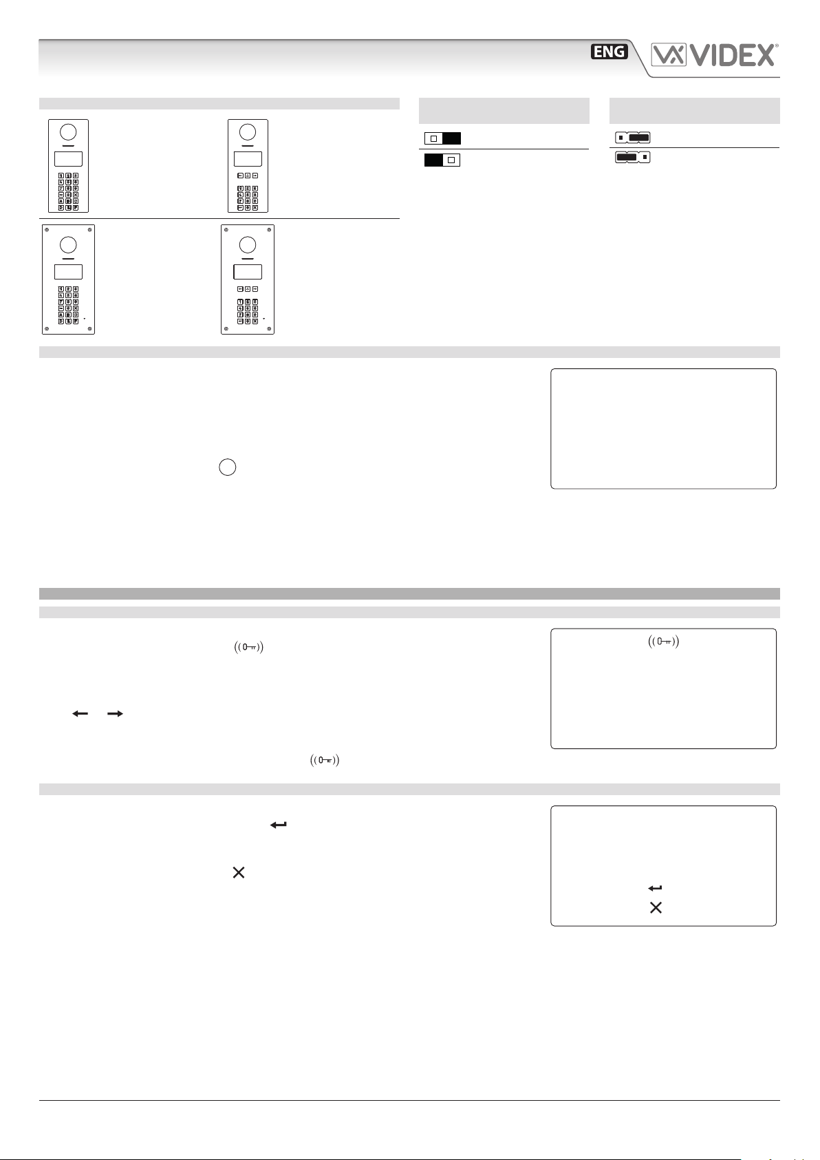
4000 Series Vandal Resistant Range
Art.4514 - Installation instructions
Art.4514 Audio/video digital front panel for IPure system
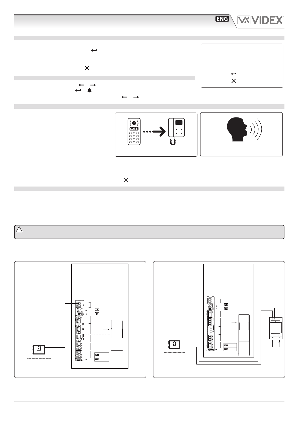
HOW TO CALL AN APARTMENT
From stand-by mode, enter a at number (see Fig. 6).
Each digit will be displayed. Pushing will conrm the at number.
If at number is present in memory and user is enabled then a call request is made, or
“NOT FOUND!” message will appear.
To delete digits or exit page press .
SCROLLING USERS
From stand-by mode, pressing or will begin scrolling. The highlighted central line
is the selected user: pressing or will make a call request.
For 15 button panel version scrolling is made using or .
HOW TO MAKE A CALL
A call request can be made by either scrolling
the user name or entering the at number.
When a call is in progress the panel will show
“Calling”as in Fig. 7.
The “CALLING” message alternates with at
number (if user has made a call by typing num-
ber) or name (if the scroll was used).
If the call is answered a conversation can begin.
If the call is answered the display will be as per Fig. 8. The conversation timeout is programmable.
When the door is released, the animation appears on the screen.
To delete a call request or close a converastion press . The panel will show the “CALL END” message.
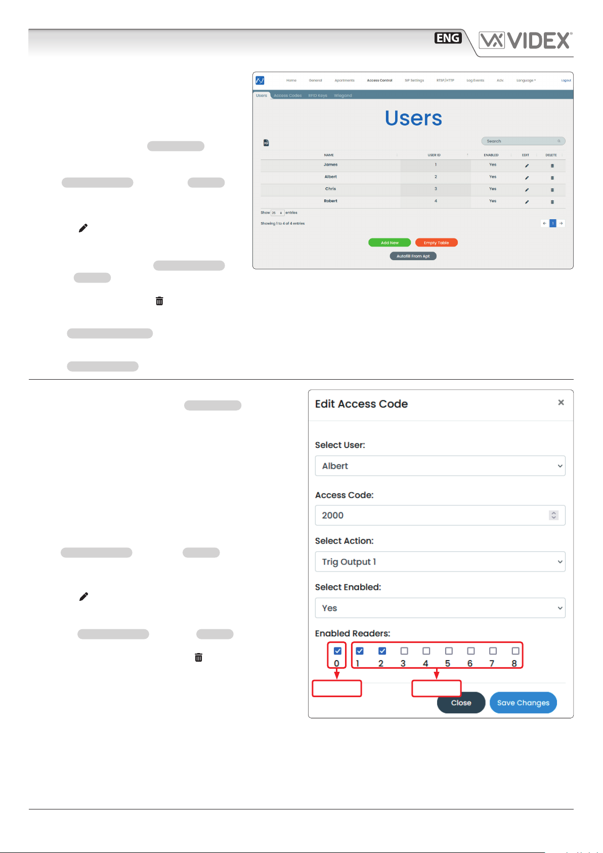
HOW TO CONNECT AN ELECTRIC LOCK
The“door-open” relay can operate either as“capacitive discharge” or “dry contact” mode.
• In “capacitive discharge” operation mode the relay’s contacts, when active, supply directly the lock (12Vac/dc 1A max) for a
moment. You don’t need a power supply for the lock and the door opening time programmed do not aect the activation time.
• In “dry contact” operation mode the relay works in a traditional way, a power supply or a power source is needed to operate the
lock (12-24Vac/dc 2A max), and activation lasts according to the door opening time programmed.
* NOTE: in “capacitive discharge” modality (electric lock 12Vac/dc 1A max) the relay time cannot be more than 6 sec-
onds because it could overhead the device.
A possibile deterioration of the mechanical performance of the electric lock, might cause the “capacitive discharge”to malfunction
in time. In case the electric lock is used in very dusty environments or in an abnormal climate condition, we suggest to use the“open
door”relay in“dry contacts”mode.
Fig. 9 Using capacitive discharge Fig. 10 Using separate P.S.U.
12Vac 1.6A Max using Art.321
24Vac/dc 2A Max using other power supplies12Vca/cc 1A Max
12V ac/dc
·12V AC/DC 1A Max
Using Capacitive Discharge
12V
230V
50/60 Hz
ART.321
230V
·12V AC 1.6A Max using Art.321
·24V AC/DC 2A Max using other
power supplies
Videx Electronics S.p.A.
Via del Lavoro 1, 63846 Monte Giberto (FM)
Phone: +39 0734 631669 - Fax +39 0734 631669
Autore:
Data modifica:
Data creazione:Title:
Notes:
Titolo:
Note: Cod.File:
Foglio
/ 11
Lorenzo Silla
4514-g001.dwg
06/02/2023
07/02/2023
.
4514V collegamento serratura elettrica
4514V electric lock connections
.
12V ac
IP:xxx.xxx.xxx.xxx
GND
+12V
OPEN
CLOSE
Prog.
GND
B
A
D0
D1
LR
LG
GNDI
IN2
IN1
NO2
NC2
C2
NO1
NC1
C1
POWER
RS-485
WIEGAND INPUTS RELAY2 RELAY1
RS-485 BUS
TERMINATION
LAN
Dry Contact
Capacitor
Discharge
Art.4514V
Serratura Elettrica
Electric Lock
Serratura Elettrica
Electric Lock
Using separate P.S.U
IP:xxx.xxx.xxx.xxx
GND
+12V
OPEN
CLOSE
Prog.
GND
B
A
D0
D1
LR
LG
GNDI
IN2
IN1
NO2
NC2
C2
NO1
NC1
C1
POWER
RS-485
WIEGAND INPUTS RELAY2 RELAY1
RS-485 BUS
TERMINATION
LAN
Dry Contact
Capacitor
Discharge
Art.4514V
123
to conrm
to canc
Fig. 6
calling
Fig. 7
1 CONCIERGE
Fig. 8