ATD Tools ATD-10504 User manual
Specifications
• Voltage: 120V/60Hz
• Amps: 8A
• No Load Speed: 11,000 RPM
• Wheel Size: 4-1/2” Diameter
• Safety Lock-Off Switch: Yes
• Spindle Lock: Yes
• Spindle Thread: 5/8”-11
• Cord Length: 6’
• Tool Weight: 6.5 lbs
ATD-10504
Angle Grinder
Owner’s Manual
WARNING: This product contains chemicals, including lead, known to the State of California to cause cancer,
birth defects or other reproductive harm. Wash hands after handling.
(REV 02/17)

Know Your Product
1. Alloy gear case
2. Spindle lock button
3. Lock-on slide switch
4. On/off switch
5. Side handle
6. Adjustable safety guard
7. 4 1/2” Grinding disc
8. Safety guard adjustment bolt
9. Pin spanner
10. Outer flange
11. Inner flange
Safety Instructions
Warning! When using mains-powered tools, basic safety precautions, including the
following, should always be followed to reduce risk of fire, electric shock, personal injury and
material damage.
Read the whole manual carefully and make sure you know how to switch the tool off, in an
emergency, before operating the tool.
Save these instructions and other documents supplied with this machine for future reference.

Electric Safety
The electric motor has been designed for 120V only. Always check that the power supply
corresponds to the voltage on the rating plate.
If the supply cord is damaged, it must be replaced by a qualified electrician or a power tool
repairer in order to avoid a hazard.
Note: Double insulation does not take the place of normal safety precautions when operating
this tool. The insulation system is for added protection against injury resulting from a possible
electrical insulation failure within the tool.
Using an extension cord
Always use an approved extension cord suitable for the power input of this tool. Before use,
inspect the extension cord for signs of damage, wear and aging. Replace the extension cord if
damaged or defective. When using an extension cord on a reel, always unwind the lead
completely. Use of an extension cord not suitable for the power input of the tool or which is
damaged or defective may result in a risk of fire and electric shock.
General Safety Rules
Warning! Read all instructions. Failure to follow all instructions listed below may result in
electric shock, fire and/or serious injury. The term "power tool" in all of the warnings listed
below refers to your mains-operated (corded) power tool or battery-operated (cordless)
power tool. Save these instructions
Work area
x Keep work area clean and well lit. Cluttered and dark areas invite accidents.
x Do not operate power tools in explosive atmospheres, such as in the presence of
flammable liquids, gases or dust. Power tools create sparks which may ignite the dust
or fumes.
x Keep children and bystanders away while operating a power tool. Distractions can
cause you to lose control.
Electrical safety
x Power tool plugs must match the outlet. Never modify the plug in any way. Do not use
any adapter plugs with earthed (grounded) power tools. Unmodified plugs and matching
outlets will reduce risk of electric shock
x Avoid body contact with earthed or grounded surfaces such as pipes, radiators, ranges
and refrigerators. There is an increased risk of electric shock if your body is earthed or
grounded.
x Do not expose power tools to rain or wet conditions. Water entering a power tool will
increase the risk of electric shock.
x Do not abuse the cord. Never use the cord for carrying, pulling or unplugging the power
tool. Keep cord away from heat, oil, sharp edges or moving parts. Damaged or
entangled cords increase the risk of electric shock.
x When operating a power tool outdoors, use an extension cord suitable for outdoor use.
Use of a cord suitable for outdoor use reduces the risk of electric shock.
x If operating a power tool in a damp location is unavoidable, use a residual current
device (RCD) protected supply. Use of an RCD reduces the risk of electric shock.

Personal safety
x Stay alert, watch what you are doing and use common sense when operating a power
tool. Do not use a power tool while you are tired or under the influence of drugs, alcohol
or medication. A moment of inattention while operating power tools may result in
serious personal injury.
x Use safety equipment. Always wear eye protection. Safety equipment such as dust
mask, non-skid safety shoes, hard hat, or hearing protection used for appropriate
conditions will reduce personal injuries.
x Avoid accidental starting. Ensure the switch is in the off-position before plugging in.
Carrying power tools with your finger on the switch or plugging in power tools that have
the switch on invites accidents.
x Remove any adjusting key or wrench before turning the power tool on. A wrench or a
key left attached to a rotating part of the power tool may result in personal injury.
x Do not overreach. Keep proper footing and balance at all times. This enables better
control of the power tool in unexpected situations.
x Dress properly. Do not wear loose clothing or jewelry. Keep your hair, clothing and
gloves away from moving parts. Loose clothes, jewelry or long hair can be caught in
moving parts.
x If devices are provided for the connection of dust extraction and collection facilities,
ensure these are connected and properly used. Use of these devices can reduce dust-
related hazards.
Power tool use and care
x Do not force the power tool. Use the correct power tool for your application. The correct
power tool will do the job better and safer at the rate for which it was designed.
x Do not use the power tool if the switch does not turn it on and off. Any power tool that
cannot be controlled with the switch is dangerous and must be repaired.
x Disconnect the plug from the power source and/or the battery pack from the power tool
before making any adjustments, changing accessories, or storing power tools. Such
preventive safety measures reduce the risk of starting the power tool accidentally.
x Store idle power tools out of the reach of children and do not allow persons unfamiliar
with the power tool or these instructions to operate the power tool. Power tools are
dangerous in the hands of untrained users.
x Maintain power tools. Check for misalignment or binding of moving parts, breakage of
parts and any other condition that may affect the power tools operation. If damaged,
have the power tool repaired before use. Many accidents are caused by poorly
maintained power tools.
x Keep cutting tools sharp and clean. Properly maintained cutting tools with sharp cutting
edges are less likely to bind and are easier to control.
x Use the power tool, accessories and tool bits etc. in accordance with these instructions
and in the manner intended for the particular type of power tool, taking into account the
working conditions and the work to be performed. Use of the power tool for operations
different from those intended could result in a hazardous situation.

Service
x Have your power tool serviced by a qualified repair person using only identical
replacement parts. This will ensure that the safety of the power tool is maintained.
x Safety Warnings Common for Grinding:
x This power tool is intended to function as a grinder. Read all safety warnings,
instructions, illustrations and specifications provided with this power tool. Failure to
follow all instructions listed below may result in electric shock, fire and/or serious injury.
x Operations such as sanding, wire brushing, polishing or cutting-off are not
recommended to be performed with this power tool. Operations for which the power tool
was not designed may create a hazard and cause personal injury.
x Do not use accessories which are not specifically designed and recommended by the
tool manufacturer. Just because the accessory can be attached to your power tool, it
does not assure safe operation.
x The rated speed of the accessory must be at least equal to the maximum speed marked
on the power tool. Accessories running faster than their rated speed can break and fly
apart.
x The outside diameter and the thickness of your accessory must be within the capacity
rating of your power tool. Incorrectly sized accessories cannot be adequately guarded
or controlled.
x The arbor size of wheels, flanges, backing pads or any other accessory must properly fit
the spindle of the power tool. Accessories with arbor holes that do not match the
mounting hardware of the power tool will run out of balance, vibrate excessively and
may cause loss of control.
x Do not use a damaged accessory. Before each use inspect the accessory such as
abrasive wheels for chips and cracks, backing pad for cracks, tear or excess wear, wire
brush for loose or cracked wires. If power tool or accessory is dropped, inspect for
damage or install an undamaged accessory. After inspecting and installing an
accessory, position yourself and bystanders away from the plane of the rotating
accessory and run the power tool at maximum no-load speed for one minute. Damaged
accessories will normally break apart during this test time.
x Wear personal protective equipment. Depending on application, use face shield, safety
goggles or safety glasses. As appropriate, wear dust mask, hearing protectors, gloves
and workshop apron capable of stopping small abrasive or work piece fragments. The
eye protection must be capable of stopping flying debris generated by various
operations. The dust mask or respirator must be capable of filtrating particles generated
by your operation. Prolonged exposure to high intensity noise may cause hearing loss.
x Keep bystanders a safe distance away from work area. Anyone entering the work area
must wear personal protective equipment. Fragments of work piece or of a broken
accessory may fly away and cause injury beyond immediate area of operation.
x Hold power tool by insulated gripping surfaces only, when performing an operation
where the cutting accessory may contact hidden wiring or its own cord. Cutting
accessory contacting a "live" wire may make exposed metal parts of the power tool
"live" and shock the operator.
x Position the cord clear of the spinning accessory. If you lose control, the cord may be
cut or snagged and your hand or arm may be pulled into the spinning accessory.
x Never lay the power tool down until the accessory has come to a complete stop. The
spinning accessory may grab the surface and pull the power tool out of your control.
x Do not run the power tool while carrying it at your side. Accidental contact with the
spinning accessory could snag your clothing, pulling the accessory into your body.
x Regularly clean the power tool's air vents. The motor's fan will draw the dust inside the
housing and excessive accumulation of powdered metal may cause electrical hazards.
x Do not operate the power tool near flammable materials. Sparks could ignite these
materials.
x Do not use accessories that require liquid coolants. Using water or other liquid coolants
may result in electrocution or shock.

Further safety instructions for all operations:
x Maintain a firm grip on the power tool and position your body and arm to allow you to
resist kickback forces. Always use auxiliary handle, if provided, for maximum control
over kickback or torque reaction during start-up. The operator can control torque
reactions or kickback forces, if proper precautions are taken.
x Never place your hand near the rotating accessory. Accessory may kickback over your
hand.
x Do not position your body in the area where power tool will move if kickback occurs.
Kickback will propel the tool in direction opposite to the wheel's movement at the point
of snagging.
x Use special care when working corners, sharp edges etc. Avoid bouncing and snagging
the accessory. Corners, sharp edges or bouncing have a tendency to snag the rotating
accessory and cause loss of control or kickback.
x Do not attach a saw chain woodcarving blade or toothed saw blade. Such blades create
frequent kickback and loss of control.
Additional Safety Instructions for Angle Grinder
xUse only wheel (disc) types that are recommended for your power tool and the
specific guard designed for the selected wheel. Wheels for which the power tool
was not designed cannot be adequately guarded and are unsafe.
xThe guard must be securely attached to the power tool and positioned for
maximum safety, so the least amount of wheel (disc) is exposed towards the
operator. The guard helps to protect operator from broken wheel fragments and
accidental contact with wheel.
xWheels (discs) must be used only for recommended applications. For example:
do not grind with the side of a cut-off wheel. Abrasive cut-off wheels are intended for
peripheral grinding, side forces applied to these wheels may cause them to shatter.
xAlways use undamaged wheel (disc) flanges that are of correct size and shape for
your selected wheel. Proper wheel flanges support the wheel thus reducing the
possibility of wheel breakage. Flanges for cut-off wheels may be different from grinding
wheel flanges.
xDo not use worn down wheels from larger power tools. Wheels intended for larger
power tools are not suitable for the higher speed of a smaller tool and may burst.
xMake sure the wheel (disc) is not contacting the work piece before the tool is
turned on. Having the wheel resting on the work piece before starting the tool could
result in the tool kicking as it grips the work piece, this could cause potential personal
harm and/or material damage.
xCheck the wheel (disc) carefully for cracks or damage before operation. Replace
cracked or damaged wheels immediately.
xBefore operation of the tool an actual work piece, let it run for a few moments.
Watch for vibration or wobbling that could indicate poor installation of the wheel (disc) or
a poorly balanced wheel.
xWatch out for flying sparks. Hold the tool at an angle of approximately 15 - 30° to the
work piece surface.
xUse only wheels (discs) having a maximum operating speed at least as high as
the “No load speed” marked on the rating label of this tool. Using a wheel with a
lower maximum speed rating than the tool is dangerous and could result in the wheel
breaking during use causing potential personal harm and/or material damage.
xIt should never be necessary to force the tool. If rotational speed drops abnormally,
the pressure should be released immediately. Little more than the weight of the tool
should be applied. Applying (forcing) excessive pressure can cause dangerous wheel
breakage or burn out of the tools motor.

Assembly/Adjustments
BE SURE TO DISCONNECT THE ANGLE GRINDER FROM THE POWER
SUPPLY BEFORE ATTACHING OR REMOVING A DISC OR ATTACHMENT.
Make sure the grinding or cutting disc is mounted with the label on top (facing the angle
grinder). If you are fitting any other kind of attachment, refer to attachment fitting
instructions. ATD Tools will not be responsible for any damage or injury caused due to
the incorrect fitting of grinding or cutting discs or any other kind of attachment.
Incorrect attachments can cause the motor to burn out, generally damage the tool
and/or cause injury.
Assembling the side handle
The side handle (5) can be fitted on either the left or the right hand side of your grinder.
Choose the most appropriate position considering user comfort (preferred hand) and the task
at hand.
Attaching and removing the grinding disc
x Inspect the grinding disc (7) before fitting and during use to ensure it is not deformed or
cracked.
x Do not fit or use a grinding disc (7) for cutting applications - For cutting, use a cutting
disc and ask your hardware retailer for advice regarding the type of cutting disc you
require for the material you wish to cut. Grinding discs are used for grinding metal only.
x The grinding disc (7) is not solid. It is made from grit which is bonded together with
reinforcement and adhesives. It is always possible that a part of the disc can dislodge
and fly away from the tool at high speed. This is why you must wear the appropriate
safety equipment (glasses, gloves and protective clothing) described herein and follow
all safety instructions also described herein.
x Do not use any kind of attachment (discs or otherwise) that has a diameter greater than
41/2”.
Warning! Removing the safety guard (6) is a serious safety concern; this action will
also void your warranty.
x Remove the outer flange (10) by hand if loose. If tight, depress the spindle lock button
(2) at the top of the alloy gear case (1); rotate the spindle (or disc if attached) to locate
the lock position. Once the spindle is locked and cannot be rotated, use the pin spanner
(9) supplied to loosen the outer flange (10).
x Never press the spindle lock button (2) when the disc or attachment is still rotating.
Always wait until the disc or attachment has stopped rotating before pressing the
spindle lock button (2). Pressing the spindle lock button (2) will cause damage to the
spindle lock mechanism which will not be covered under warranty.
x Holding the angle grinder with the spindle facing upwards, ensure the inner flange (11)
is on the spindle and located correctly. The two machined flat sections on one side of
the inner flange (11) must face the angle grinder and locate in the appropriate position
on the spindle.
x Insert the hole in the grinding disc (7) over the angle grinder spindle with the disc label
facing the angle grinder. The hole in the disc should be located onto the spindle.
Ensure the hole in the disc locates and fits firmly into the ring section of the inner flange
(11).

Operation
x Screw the outer flange (10) onto the spindle with the protruding ring section
facing the angle grinder. This ring section must locate with the hole in the
grinding disc (7).
x Tighten the outer flange (10) by locking the spindle (using the spindle lock
button) and then tightening the outer flange (10) with the pin spanner (9)
provided.
x Removal of the disc is conducted in reverse order to the above.
x Regularly check that the outer flange has not loosened during use.
Note: When fitting a cutting disc or diamond wheel, the ring section on the outer
flange should face away from the disc / wheel in order for the face of the outer
flange (10) to sit flush against the bottom side of the disc / wheel.
Note: Disc/wheel label or marking, should face towards inner flange.
On/off switch
The ON/OFF switch (4) is provided with a lock button (3). Simply pull the trigger
then push in the button to lock the trigger in the ‘ON’ position. To unlock, pull the
trigger a second time.
The lock button is used to aid in reducing fatigue in the hands and arms when
operating the tool for lengthy periods.
When pressed, this button located on top of the head, is used to lock the spindle
Safety guard
The safety guard (6) is assembled to your tool for your protection. The safety
guard (6) will protect you from any dislodging objects or materials that may be
ejected by the cutting/grinding discs during normal operation. This guard (6) will
protect you from any accidental contact of the disc with your hands, fingers and
any other parts of your body.
To adjust the safety guard (6), first disconnect the tool from the power supply.
Now loosen the Allen key bolt by using the Allen key. Rotate the safety guard (6)
into the required position, and then refasten the bolt. Ensure the safety guard (6)
is firmly secured prior to use.
Basic abrasive cutting procedure
First ensure the work piece is securely held down (by both sides of the work piece
if possible). Turn on the angle grinder and proceed to start the cut gently - do not
“bump” the cutting disc to start a cut. Feed the disc through the work as fast as
possible without slowing the cutting disc in the cut or laboring the machine. The
abrasive cutting operation generates a great deal of localized heat which causes
rapid expansion of the piece being cut. Discs operated at speeds significantly
below the efficient speed or if fed through the cut too slowly will generate

excessive heat. Such heat can cause rapid disc wear, fraying around the edge of
the reinforced discs and disc breakage.
Basic grinding procedure
First ensure the work piece is securely held down (by both sides of the work piece
if possible). Turn on the angle grinder and proceed to start grinding your work
piece gently - do not “bump” the grinding disc on your work piece as this may
damage your grinding disc. The optimal grinding position is to hold your grinder at
approximately 10-15º to your work piece and grind slowly. This will assist you and
prevent deep gouging.
Maintenance
• Keep ventilation slots of the grinder clean at all times and prevent any foreign matter
from entering.
• If the enclosure of the grinder requires cleaning do not use solvents but a moist soft
cloth only.
• The grease in the gearbox will require replacement / replenishment after extensive use of
the grinder. Please see a qualified electrical repairer to provide this service.
• Blow out the unit through the rear ventilation slots with compressed air periodically to
ensure a dust free area around the switch.
• Carbon brushes should be replaced before they wear out. Both carbon brushes should
be replaced at the same time.
Sparking visible through the housing air vents. A small amount of sparking may be
visible through the housing vents. This is normal and does not indicate a problem.
Excessive sparking visible through the housing air vents and/or the tool FAILING
to operate May indicate the carbon brushes have worn down and need to be replaced.
Carbon brushes should only be replaced by a qualified electrician or power tool repairer.
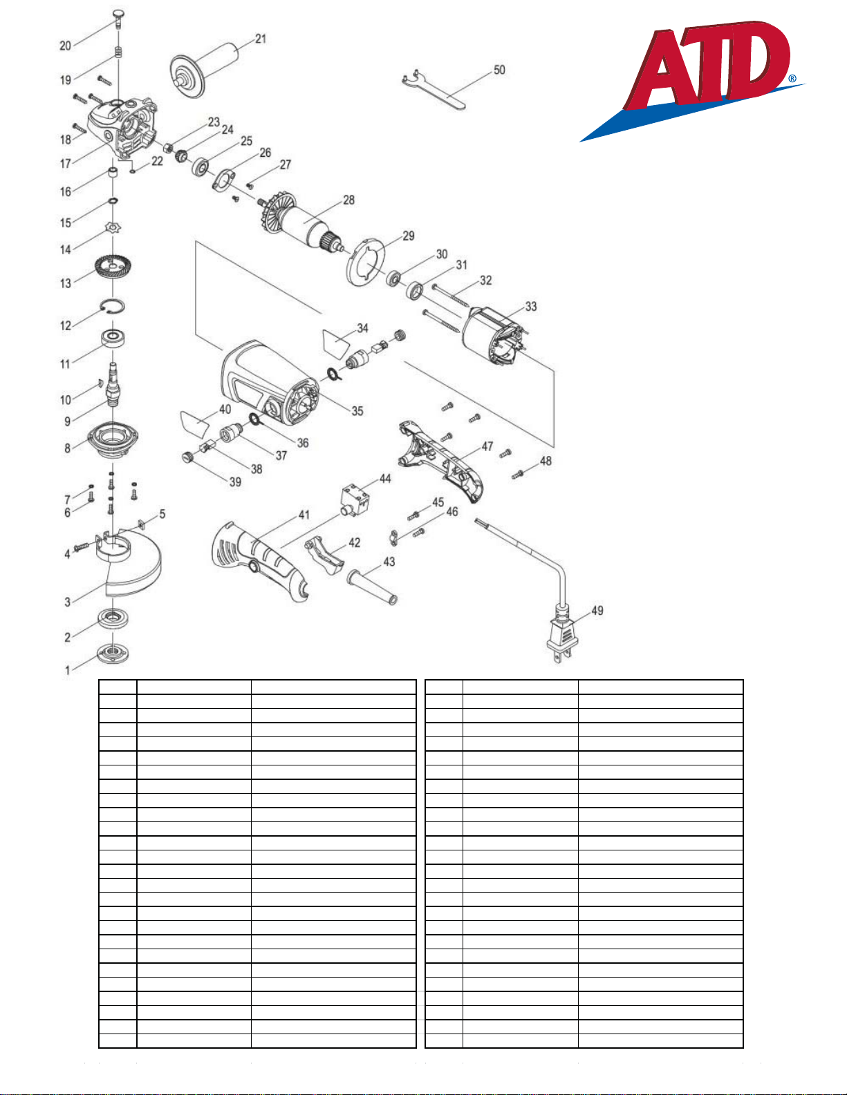
ITEM# ORDERING PART# PART DESCRIPTION ITEM# ORDERING PART# PART DESCRIPTION
1 PRT10504-01 OUTER FLANGE 26 PRT10504-26 BEARING COVER
2 PRT10504-02 INNER FLANGE27PRT10504-27SCREW M5X10
3 PRT10504-03 WHEEL GUARD φ115 28 PRT10504-28 ARMATURE
4 PRT10504-04 SCREW M5X18 29 PRT10504-29 WIND BAFFLE
5 PRT10504-05 SQUARE NUT M5 30 PRT10504-30 BALL BEARING 608.2Z
6 PRT10504-06 SCREW M4X14 31 PRT10504-31 BEARING CAP
7PRT10504-07SPRING WASHER φ432PRT10504-32 SCREW ST4X65
8 PRT10504-08 GEARBOX COVER 33 PRT10504-33 STATOR
9 PRT10504-09 SPINDLE 34 PRT10504-34 LABEL
10 PRT10504-10 KEY 3X3.7X10 35 PRT10504-35 HOUSING
11 PRT10504-11 BALL BEARING 6201.2RS 36 PRT10504-36 RING TERMINAL
12 PRT10504-12 CIRCLIP φ32 37PRT10504-37-39 BRUSH HOLDER & CAP, PAIR
13 PRT10504-13 LARGE GEAR 38 PRT10504-38 CARBON BRUSH, PAIR
14 PRT10504-14 WAVE WASHER φ10Xφ15 39 PRT10504-37-39 BRUSH HOLDER & CAP, PAIR
15 PRT10504-15 CIRCLIP φ10 40 PRT10504-40 BRAND LABEL
16 PRT10504-16 OIL BEARING41 PRT10504-41 HANDLE
17 PRT10504-17GEAR BOX 42 PRT10504-42 TRIGGER
18 PRT10504-18 SCREW ST4X28 43 PRT10504-43 CORD SHEATH
19 PRT10504-19 SPINDLE LOCK SPRING44 PRT10504-44 SWITCH
20 PRT10504-20 SPINDLE LOCK BUTTON 45 PRT10504-45 SCREW ST4X14
21 PRT10504-21 AUXILIARY HANDLE 46 PRT10504-46 CORD CLAMP
22 PRT10504-22 CHECK RING 47 PRT10504-47 HANDLE COVER
23 PRT10504-23HEX. THICK NUT M8X1 48 PRT10504-48 SCREW ST4X16
24 PRT10504-24 PINION 49 PRT10504-49 POWER CORD
25 PRT10504-25 BALL BEARING 6000.2RS 50 PRT10504-50 WRENCH
ATD-10504
Learn more about power grinders and rotary tools we have.
Table of contents
Other ATD Tools Grinder manuals


Popular Grinder manuals by other brands


Colombini
Colombini ANGEL.ST.18 Instructions for use

AEG
AEG AG 8-100 Original instructions

Universal Tool
Universal Tool UT2710 General Safety Information & Replacement Parts

Sparky Group
Sparky Group M 750E HD Compact Original instructions

AEG
AEG GSL 600 E Original instructions

EINHELL
EINHELL TC-BG 150 Original operating instructions


