Atech Flash Technology PRO-9 User manual

AtechFlash Technology, Inc.
www.atechflash.com
PRO 9
USB 2.0 Multiple Flash Card Reader
User's Manual
Windows 98SE or Windows 2000 users
Please perform software setup first before proceeding
to hardware setup.

Congratulations on the purchase of your new AtechFlash
Technology PRO 9 flash reader/writer. PRO 9 is a read/write
device that supports multiple formats of flash memory cards
and we recommend that you read this manual carefully to
become familiar with the operation of the product. This
manual explains the features and specifications of your new
PRO 9 reader, as well as the installation in a few simple
steps. Please retain this guide for future reference.
If you have questions regarding your PRO 9 reader, please
call our technical support hotline at toll free number (US
only)
1-866-85-ATECH (1-866-852-8324)
or email us at
or visit our website at
www.atechflash.com
All trademarks, service marks, trade names and copyrights are
properties of their respective owners.

Table of Content
1. Introduction...........................................1
2. Key Features........................................2
3. System Requirement............................3
4. Cable Description.................................4-5
5. Before Installation.................................6
6. Software setup......................................7
7. Hardware setup....................................8-12
8. Using PRO 9 Multiple Card reader....13
9. Specifications.......................................14

Introduction
PRO 9 is a multi-function, read and write device for today's
most popular flash memory card formats. It brings you the
benefit of ultra high speed data transferring between your
desktop PC and your personal electronic devices, such as
Digital Cameras, MP3 Players, PDAs, Voice Recorders,
Pocket PCs and many other electronic devices that adopt
the flash media formats supported by this product.
Utilizing the most widely equipped USB (Universal Serial
Bus) interface in PCs, PRO 9 is based on latest USB 2.0
technology with the capability of of transferring data up to
480 Mb/sec via USB 2.0 connection. Backward compatibility
design of PRO 9 also allows you to connect to PCs with
USB 1.1 interface, operating at USB 1.1 speed.
Convenient feature like Plug-and-Play makes it easy to
setup PRO 9 on your computer. On Operating Systems like
Windows ME and Windows XP, PRO 9 does not require
prior installation of software driver at all.
With the versatile design, PRO 9 can be used externally as
a portable unit or mounted internally to a standard 3.5" drive
bay of your PC.
1

Features
Ultra High speed USB 2.0 interface - up to 480 Mb/s
transfer rate to access to your flash media cards. It is also
backward compatible with USB 1.1 interface.
Internal or External Use - can be installed into a
computer 3.5" drive bay or use externally.
Front IEEE 1394 (FireWire) pass-through port* - for
easy connection to FireWire devices, such as Digital Video
(DV) camcorders, FireWire Hard Drives and etc.
4 independent card slots - allow you to access 4
different media cards concurrently and direct file transferring
among media cards in different slots.
USB Bus powered - no additional power adaptor or
battery required.
Fully Plug and Play** - No software driver needed on
Windows ME, XP or later.
Hot-Swappable - connect or disconnect reader without
having to turn your computer off.
Supports all 8 popular flash card formats-
CF - Compact Flash™card (Type I/II)
MS - Memory Stick™
MS Pro - Memory Stick Pro™
SM - SmartMedia™Card (3.3V)
SD - Secure Digital™Card
MMC - MultiMedia™Card
MD - IBM MicroDrive™
xD - xD picture card™***
* System with IEEE 1394 interface required.
** Software driver required on Windows 98 SE / 2000.
*** xD-Picture Card™ is a trademark owned by Fuji Photo
Film Co., Ltd.
2

System Requirements
Operating System Requirement
Windows 98 SE*
Windows ME
Windows 2000*
Windows XP
A CD ROM Drive may also be required to access the Setup
CD when setting up PRO 9 on Windows 98 / 98SE / 2000
For External Setup*
- IBM PC compatible computer with USB port (USB 2.0 or
USB 1.1).
For Internal setup*
- IBM PC compatible computer with USB connection (USB
2.0 or USB 1.1)
- Empty external 3.5" drive bay
- On board USB pin header (refer to your motherboard
manual)
* PRO 9 must be connected to an USB 2.0 port if USB 2.0
performance is desired.
3

Cable Description
Depending on which version you have purchased, following
cables may be included in your PRO 9 Multiple card reader /
writer package. Before attempting to connect, please read this
manual carefully and determine if software driver setup is
required first.
External USB cable. This cable connects PRO 9 Card
Reader to the USB port of your computer. (For external
setup only)
Internal USB Cable. This cable connects PRO 9 Card
Reader to the USB pin header on your motherboard.
Due to motherboards may have different USB pin
layouts, wire reassignment may be required. Please
refer to your motherboard manual for USB header pin
assignment information. (For internal setup only).
External USB Cable
Internal USB cable
To USB port
To PRO 9 reader
To PRO 9 Reader -
To Motherboard
USB Header
4

Cable Description 5
Standard 6-pin to 6-pin IEEE 1394 (FireWire) cable.
This cable connects PRO 9 Card Reader to the FireWire
port on your PCI IEEE 1394 FireWire add-on card or the
IEEE 1394 port from your motherboard (if equipped). This
connection is only necessary if you intend to use the front
IEEE 1394 port of PRO 9 Card Reader.
Please note that the front IEEE 1394 port of PRO 9
Card Reader is just a pass-through extension from the
IEEE 1394 port in your PC, for port access convenience.
PRO 9 Card Reader is not a IEEE 1394 device and it
will not function via IEEE 1394 connection alone.
USB cable must be connected in order to use PRO 9.

Before Installation
Important !!!!
Windows 98, Windows 98SE or Windows
2000 users
Please perform software setup first before attempting to
connect PRO 9 reader.
Windows ME or Windows XP users
Please DO NOT install any software driver or use the setup
driver file in PRO 9 Setup CD. Proceed to Hardware setup
directly.
Connecting to USB 1.1 port
PRO 9 USB 2.0 Multiple Flash Card Reader is backward
compatible with USB 1.1 interface. However, USB 1.1
performance can only be expected when connect to an USB
1.1 port.
Internal setup requires your computer case cover to be
removed to access inside components. Please refer to your
computer manual for further instruction if needed.
Please also be sure to remove the power plug of your
computer to avoid electrical shock or damage to your
system.
6

7
Software Setup
Windows ME or Windows XP users
Please DO NOT install any software driver or use the setup
driver file in PRO 9 Setup CD. Proceed to Hardware setup
directly.
(1) Close all applications that are currently running in your
computer, including applications running in background.
(2) Insert PRO 9 Setup CD into you CD ROM drive and
locate a "setup.exe" file in "PC" folder.
(3) Double click on "setup.exe" file will lead you into setup
program.
(4) Follow setup instruction on your screen.
(5) Once software setup is completed, Please proceed to
Hardware Setup.
<<<To Remove PRO 9 Driver from your computer>>>
In case if you want to remove PRO 9 setup driver from your
computer, please follow the steps below :
(1) Go to [Start] [Programs] [PRO-9 (USB2.0)] and select
[Remove PRO-9 (USB2.0)], then follow the instruction on
your screen.

Hardware Setup
Windows 98, Windows 98SE or Windows 2000 users
Please perform software setup first before proceeding to
hardware setup.
External Setup
To set up PRO 9 reader externally, simply use External USB
cable to connect PRO 9 reader to an USB port on your
computer. USB ports are usually located at the back of your
computer, next to the keyboard and mouse connectors.
8
It is not necessary to shut down your computer to make the
connection. As soon as PRO 9 reader is connected to your
USB port, your computer shall detect this reader device and
start to build up its driver automatically.
To computer USB port
External USB cable

Hardware Setup 9
Internal Setup
Internal setup requires your computer case cover to be
removed. Like a standard 3.5" floppy drive, PRO 9 reader
has 3 screw holes on both sides. Insert PRO 9 reader into
one of the empty external 3.5" drive bay and align PRO 9
reader bezel with your computer front bezel evenly. Apply
screws on both sides to secure the reader into drive bay.
Use Internal USB cable to connect PRO 9 reader to the USB
pin header on your motherboard. Connect the molded end of
cable to the USB connector at the back of PRO 9 reader.
To Motherboard USB header
Internal USB cable

Hardware Setup 10
Depending on the pin layout on your motherboard USB
header, it may be necessary rearrange the color wires of
Internal USB cable to match the USB pin assignment.
Please refer to your motherboard manual for USB header
pin assignment information.
Internal USB cable connect to USB header
Internal USB cable is consist of Red, White, Green and
Black wires. Each color wire shall be connected to a specific
pin on the USB header.
Red wire = Power (VCC)
White wire = P- (Data-)
Green wire = P+ (Data+)
Black wire = Ground (GND)

Hardware Setup 11
<<< Example >>>
Here is an example base on the motherboard we have.
According to the motherboard manual, we have following pin
information on USB header:
Pin 1 = USB Power
Pin 2 = USBP2-
Pin 3 = USBP2+
Pin 4 = GND
Pin 5 = NC
Pin 6 = USB Power
Pin 7 = USBP3-
Pin 8 = USBP3+
Pin 9 = GND
Pin 10 = NC (No pin)
Therefore, we shall have:
Red wire goes to pin 1
White wire goes to pin 2
Green wire goes to pin 3
Black wire goes to pin 4
or
Red wire goes to pin 6
White wire goes to pin 7
Green wire goes to pin 8
Black wire goes to pin 9
Comparing the default wire setting on the Internal USB
cable, no wire reassignment is necessary. We can plug in
the black pin connector of Internal USB cable to the USB
header directly, with red wire goes to pin 1 or 6.

Hardware Setup 12
Please note that your motherboard USB header pin
assignment could be different from the example above. If you
need to reassign wires on Internal USB cable, please follow
the procedure below:
(1) Determine which wires you need to remove from the
black pin connectors first by referring to your motherboard
USB header pin layout.
(2) Use a needle or push pin to flip up the tiny plastic tab and
pull the wire out from the connector. Please take caution on
this step as excessive force on flipping the tab may cause
the tab to break.
(3) Repeat above step for each wire that requires changing.
(4) Insert the wire pin back into the correct slot and press the
tiny plastic tab down will hold the wire in its position.

Using PRO 9 13
Once PRO 9 reader is setup successfully, you shall have 4
Removable Disk icons created in My Computer. Each of
the icons allows you to access the flash media card in the
card slot it represents.
Using PRO 9 Multiple Card Reader is very similar to using a
floppy drive. Simply insert your flash media card into the slot
and click on the appropriate Removable Disk icon in My
Computer, it will allow you to access your flash media card
like a disk.
When removing your flash media card from PRO 9 Card
Reader slot, please make sure that the file transferring
process is fully completed before pulling your flash media
card out. Failing to do so may result in card damage.
To Remove PRO 9 Card Reader from your computer
Depending on which version of Windows you have, after the
device is setup successfully, you may have a Safely
Remove Hardware or Hardware Eject Utility or USB
Monitor Icon appeared on the lower right corner of your
desktop. Please use this utility to stop PRO 9 Card Reader
only when you need to remove the device from your system.
(for instance, to use the device on other computers). If you
shall accidentally stop the device on this utility, your PRO 9
Card Reader will stop working until system restart.
Please be advised that some electronic devices may not be
compatible with flash media cards formatted under
Windows. We strongly suggest that you format your flash
media card in the electronic device it is used.
Attention!

Specifications 14
Dimension (W x H x D): 4.02 inch x 1 inch x 4.92 inch
102 mm x 25 mm x 125 mm
Power Requirement: 5V DC, 500mA (USB Bus power)
Supported media format: Compact Flash™ (Type I & II),
IBM MicroDrive™ ,
Smart Media™ (3.3V),
MultiMedia™,
Secure Digital™,
Memory Stick™
Memory Stick Pro™
xD picture card™*
Transfer rate : Up to 480 Mbps (Via USB 2.0)
or
Up to 12 Mbps (via USB 1.1)
Supported O/S : Windows 98 SE
Windows 2000
Windows ME (No driver required)
Windows XP (No driver required)
Mac OS 9.1 or later
IEEE 1394 (FireWire) Port: (Mini) 4 Pin port (pass through),
located on product bezel.
*xD-Picture Card™is a trademark owned by Fuji Photo Film Co., Ltd.
Specifications are subject to change without further notice.
All trademarks, trade names and copyrights are properties of their
respective owners.

Atech Flash Technology, Inc.
www.atechflash.com
Table of contents
Other Atech Flash Technology Card Reader manuals
Atech Flash Technology
Atech Flash Technology PRO III User manual
Atech Flash Technology
Atech Flash Technology Dica User manual
Atech Flash Technology
Atech Flash Technology PRO-8M User manual
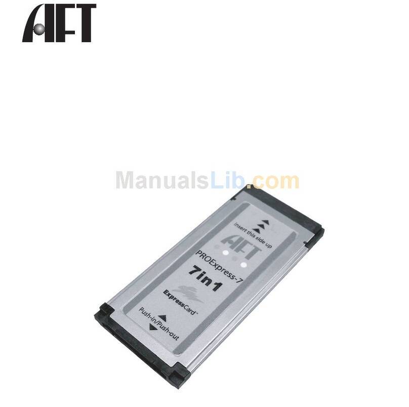
Atech Flash Technology
Atech Flash Technology PROExpress-7 User manual
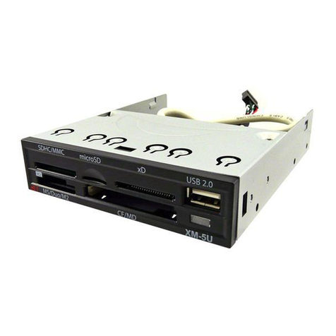
Atech Flash Technology
Atech Flash Technology XM-5U User manual

Atech Flash Technology
Atech Flash Technology PROGear-Duo User manual
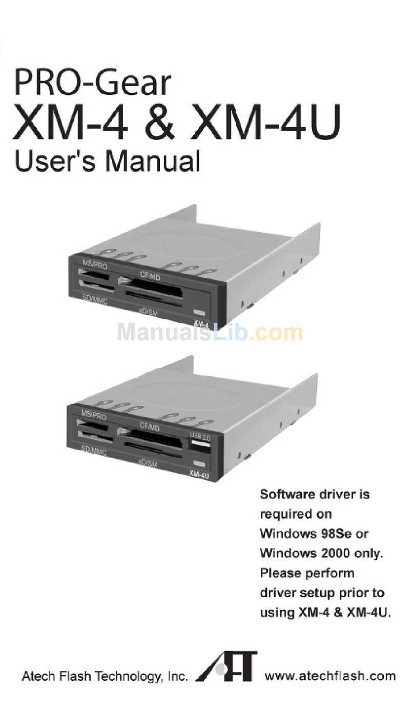
Atech Flash Technology
Atech Flash Technology PRO-GEAR XM-4 User manual
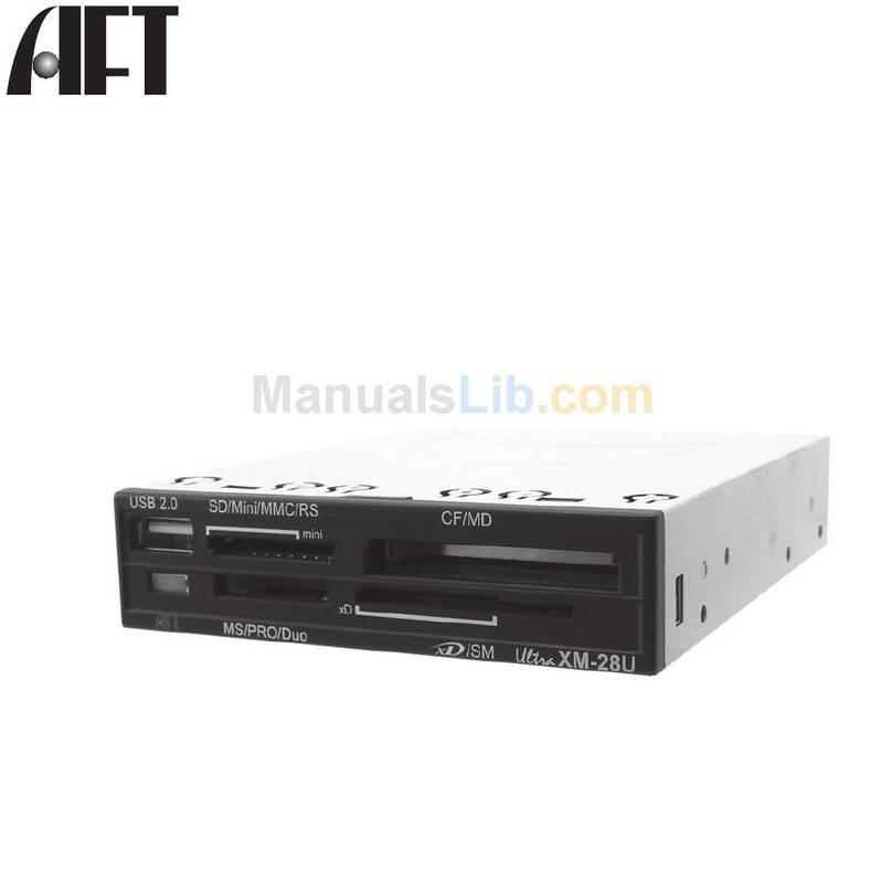
Atech Flash Technology
Atech Flash Technology XM-28U User manual
Atech Flash Technology
Atech Flash Technology PRO II User manual
Atech Flash Technology
Atech Flash Technology XM-35U User manual
