GIGA-TMS PCR340 Series User manual

PCR340 Series
Dual Frequency
RFID Reader
Manual Part Number: TM951119 REV: C JAN 2008
GIGA-TMS
REGISTERED TO ISO 9001:2000
8F, No.31, Lane 169, Kang-Ning St., Hsi-Chih Taipei Hsien, 221 Taiwan
TEL:(886) 2-2695-4214
FAX:(886) 2-2695-4213
www.gigatms.com.tw

2
Content
Specification ……………………………………………….. 3
Accessory ……………………………………………..…… 4
Technical & Operational Description ……………..…….. 5
Pin Assignment & Connection ………………..…………. 6
Importance notice of PCR340 operation ……………..… 9
Software Operation ………………………………….…… 10
Command and Packet Format …………………….……. 19

3
Specification
Card types 1. EM compatible64 bits, ASK Manchester coding
2. ISO 14443A Mifare® MF1 1K&4K / Ultralight /
DESFire
*Read Only
(For Unique Serial Number / Unique Identifier)
Frequency 125KHz、13.56MHz
Reading distance 50 mm @ 125KHz
40 mm @ 13.56MHz
Baud rate 19200、14400、9600、4800、2400 bps
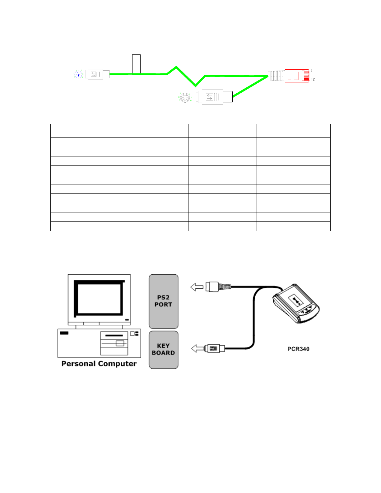
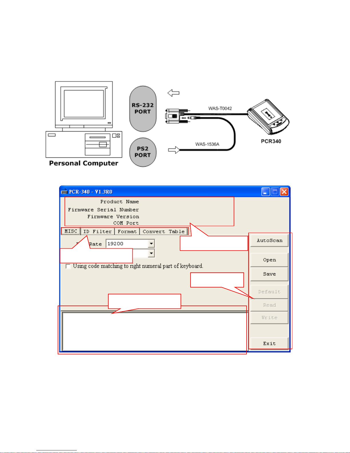
Interface PS2、USB(Human interface for PS2)、
RS232(n、8、1)
Power requirement DC 5V / 150mA、Standby 70mA
Certificate CE、FCC
Dimension 120(L) x 86(W) x 42(H) mm
Weight 150g
Operating Temp -0 to 50 Deg C
Storage Temp -10 to 60 Deg C
Humidity 10 ~ 90%

4
Accessory
MainUnit ConfigureSoftware
( PCR340 ) ( DISK5274 )
RS232 Cable
( WAS-T0042 ) PS2 Cable
( WAS-T0044 )
USB Cable
( WAS-T0043 ) Mini Din Power Cable
( WAS-1536A )

5
Technical & Operational Description
Status LED
Reaction panel
Power / Signal Port
Power / Signal port:
Direct power from USB and PS2 connection or use external power supply for RS-232
connection.
Reaction Panel
Put the card on reaction panel to read the card information.
Status LED
Status Green LED
Red LED Yellow LED Read Card
Power on Blink 2 times Blink 2 times Blink 2 times X
Ready OFF
ON OFF X
Read ok Blink 1 times ON OFF O
Firmware Management mode OFF OFF ON X

6
Pin Assignment & Connection
WAS-T0042 pin assignment:
DB9 FEMALE PIN FUNCATION
PIN2 RX
PIN3 TX
-- --
PIN5 GND
Connection:
DC 5V / 150mA
PHONE PLUG PIN FUNCATION
PIN5 TX
PIN6 RX
PIN7 VDD
PIN10 GND
CABLE P/N :
WAS-XXXX REV.X
11

7
WAS-T0043 pin assignment:
USB PLUG PIN FUNCTION
PIN1 VDD
PIN2 D+
PIN3 D-
PIN4 GND
Connection:
PHONE PLUG PIN FUNCTION
PIN7 VDD
PIN8 D+
PIN9 D-
PIN10 GND
CABLE P/N :
WAS-XXXX REV.X
1
1

8
WAS-T0044 pin assignment:
CABLE P/N :
WAS-XXXX REV.X
Connection:
PIN
NUMBER PHONE PLUG PIN MINI DIN
MALE PIN KB
FEMALE PIN
PIN1 KB_CLOCK -- CLOCK (PIN5)
PIN2 PC_CLOCK CLOCK (PIN5) --
PIN3 PC_DATA DATA (PIN1) --
PIN4 KB_DATA -- DATA (PIN1)
PIN5 -- -- --
PIN6 -- -- --
PIN7 +5V +5V (PIN4) +5V (PIN4)
PIN8 -- -- --
PIN9 -- -- --
PIN10 GND GND (PIN3) GND (PIN3)

9
Importance notice of PCR340 operation
1. To reach the ideal performance, please keep away from the
other RFID readers at about 50 cm distance while the
PCR340 is in operation to avoid the interference
2. Once continuous card reading is completed, hold for a while
for Green LED goes off to access the next card reading.
3. When the PC is powered on, do not put the RFID card on the
reaction panel to avoid an error message occurs.

10
Software Operation
First connect PCR340 with PC through RS-232 port , then run demo
software on the disk.
Step 1: Main page
Displaying information
Function keys
Product information
Functional setting tab

11
Step 2: Auto Scan
Click”AUTO SCAN” to communicate with PC. The software will detect
PCR340 and related setting. If the communication is successful, it will
show”Found PCR-340” and product information as below :
Step 3: MISC Settings
Click MISC to set “Baudrate”, “Language (Keyboard type)” & “Using
code matching to right numeral part of keyboard” if necessary and
click “Write” to save the new settings to PCR340. If baudrate is
changed, please turn off PCR340 and then you will get new baudrate
after power on PCR340.

12
Step 4: ID Filter
Click “ID Filter” to set different card formats for data output after
reading. Choose the card type and set the range/length of data
information. Then, click “Write” to save the new setting to PCR340.
Step 5: Format
Click “Format” to set Prefix code, Postfix code and OnRemove
message and Delimiter if necessary. If you want to show the card
type when you read a card, click to enable “Display Card Type”.
Then click “Write” to finish the setting and save it to PCR340.
Drag (start)&(end) to
change range
[
1K
]
= card t
yp
e
Select Hex/Dec Filter
Output Card Number in
Hex or Dec
Output Card Number in
MSB or LSB Type

13
Step 6: Convert Table
If you want to show alphabetical string instead of showing card
number, click “Convert Table” to edit the message with the following
processes:
A) Click “Format” and enable [Output by string table]
B) Then click “Convert Table” and add a card to table
Click the “Card ID” to enable/disable the ID & click the “Read” to get the card ID (After
enable "Auto Read", you’ll get the card number automatically when you read a card)
After write and Put the
card on reader

14
C) Modify “Convert Table”
D) Remove “Convert Table”
Select item
Select item

15
Step 7: Click “Save” to save all settings as .txt file.
Step 8: If you want to download the settings form the file, click “Open”
to open the file and click “Write” to download the settings.

16
Step 9: If you want to know the default setting of PCR340, click ”Read”
and download the file to show it on display area.
Step 10: Click “Default” to reset PCR340 and get default setting if
necessary. Default values are as below (red –lined area).
Default
Baud Rate 19200 (8, N, 1)
Language USA
Using code matching to right
numeral part of keyboard Disable
Prefix Empty
Postfix Empty
OnRemove Empty
Delimiter CR+LF
Display Card Type Disable
Output by String Table Disable
Card ID Filter Mifare 1K:
Mifare 4K:
UltraLight:
DesFire:
125KHz EM:
From Character = 1, Number of Characters = 8
From Character = 1, Number of Characters = 14
From Character = 1, Number of Characters = 10

17
Command and Packet Format
Packet format
PC →PCR340
STX CMD CONTENTS CHECKSUM CR
1 character 1 character 3 character 1 character 1 character
PC ←PCR340
STX REPLY CONTENTS CHECKSUM CR
1 character 1 character 3 character 1 character 1 character
Functional command
ITEM Dec Hex Function
STX 2 02 Start for test
CMD ASCII ASCII Command code
CONTENTS ASCII ASCII Contents data
CHECKSUM ASCII ASCII Check sum
REPLY 65 41 Acknowledge
CR 13 0D Carriage return
Instruction command
Command ASCII Description
C 43H Set Register
B 42H Get Register
V 56H Get Firmware Version
D 44H Get Product Name
X 58H ISP Mode
Y 59H Show Memory Data

18
Ack command
Command ASCII Contents Description
A 41H Reply information ACK + Information
N 4EH ERROR Index Table NCK + Information
Error index
Topic Error index Description
Access LEVEL 00 Access Denied or Password Error
01 Command packet is too long
02 Command packet is empty
03 Command code is out of range
COMMAND CODE
04 Illegal Command or Data
05 Database and Register is Empty
06 Record number is out of range
07 Check Sum Error
08 Memory Not Enough
DATABASE
09 Action Failure
FILE 0A File Not Exist

19
Command notation
Write to register ( ‘C’,43H )
PC→PCR340 STX +’ C ’ + Register address +’ ,’+ Write parameter + CHECKSUM + CR
PC←PCR340 STX + ACK + CR
For Instance:
PC→PCR340 02 + C + 00 + ,+ FF + 5B + 0D
PC←PCR340 02 + A + 0D
Read from register ( ‘B’,42H )
PC→PCR340 STX + ‘ B ‘ + Register address + CR
PC←PCR340 STX + ACK + Read parameter + Checksum +CR
For Instance:
PC→PCR340 02 +’ B ‘+ 00 + 0D
PC←PCR340 02 + A + FF + CD + 0D
Get F/W version ( ‘V’,56H )
PC→PCR340 STX +‘ V ‘+ CR
PC←PCR340 STX + ACK + Firmware number + Firmware version + CR
Firmware number: ROM-Txxxx。
Firmware version: Vx.xxrm ,Vx.xx: Firmware version rm: Modification frequency
For Instance:
PC→PCR340 02 +‘ V ’+ 0D
PC←PCR340 02 + A + ROM-T0611 + V1.00R2 + 0D
Get Product name ( ‘D’,56H )
PC→PCR340 STX +‘ D ’+ CR
PC←PCR340 STX + ACK + Product name + Keyboard language + CR
Product: PCR-340X。
Keyboard language: USA。
For Instance:
PC→PCR340 02 + ‘ V ’ + 0D
PC←PCR340 02 + A + PCR-340X + ,+ USA + 0D

20
Control mode ( ‘X’, 58H )
PC→PCR340 STX + X + CR
PC←PCR340 STX + A + CR
For Instance:
PC→PCR340 02 + X + 0D
PC←PCR340 02 + A + 0D
Show memory data ( ‘Y’,59H )
PC→PCR340 STX + Y + CR
PC←PCR340 STX + Register Table + CR
For Instance:
PC→PCR340 02 + Y + 0D
PC←PCR340 02 + Register Table + 0D
Other manuals for PCR340 Series
1
Table of contents
Other GIGA-TMS Card Reader manuals
Popular Card Reader manuals by other brands

SIB
SIB U-M002 manual

Crossmatch
Crossmatch Nomad 60 Wireless user guide

Sony
Sony Memory Stick MRW62E-S2 operating instructions

Diehl Metering
Diehl Metering IZAR OH BT 2 user guide

Datecs
Datecs BlueLite v2 user manual

Deister electronic
Deister electronic TranSpeed TSU 200 Wiring and installation instruction