Ateis BCU-4830A User manual

BCU-4830A
BCU-4875A
Advanced Monitored Battery Charger
User Manual
Revision History
v1.16
www.ateis.com© 2021, ATEÏS. All rights reserved. www.ateis.com

2
© 2021, ATEÏS. All rights reserved.
Table of Contents Page
1 About this manual 3
................................................................................................................................... 31.11.1 Notice signs
................................................................................................................................... 31.21.2 Safety instructions
2 BCU-4830A/BCU-4875A battery charger 5
................................................................................................................................... 52.12.1 Front panel
................................................................................................................................... 72.22.2 Rear panel
................................................................................................................................... 92.32.3 Block diagram
................................................................................................................................... 92.42.4 Top view
3 Hardware installation 11
................................................................................................................................... 113.13.1 Connect to PA system
................................................................................................................................... 133.23.2 Connect the temperature sensor
................................................................................................................................... 133.33.3 Connect to batteries
................................................................................................................................... 143.43.4 Battery balance charging
................................................................................................................................... 153.53.5 Connect the contact outputs
................................................................................................................................... 153.63.6 BCU-4830A/4875A mounting
4 Resistance measurement 16
5 Battery charging 17
6 Battery test 18
7 Battery undervoltage protection 19
8 Maintenance 20
9 Troubleshooting 21
10 Technical data 23
11 Standard and certification 25
12 Contact information 26

About this manual 3
© 2021, ATEÏS. All rights reserved.
1 About this manual
This user manual will explicitly describe the hardware installation and the software configuration,
provides installers and users the necessary information to setup and configure the system.
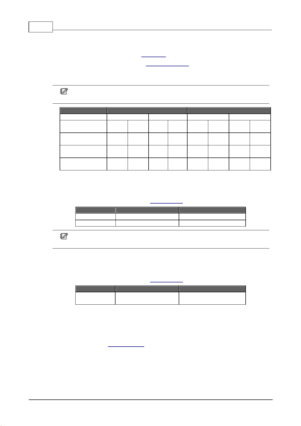
1.1 Notice signs
** The above warning is located on the back of the unit.
Explanation of Graphical Symbols
The equipment or the property can be damaged,
or persons can be lightly injured if the alert is
not observed.
To alert the user to the presence of uninsulated
“dangerous voltage” within the product’s enclosure
that may be of sufficient magnitude to constitute a
risk of electric shock to persons.
1.2 Safety instructions
Do not expose the device to extreme temperatures, direct sunlight, humidity, or dust, which could
cause fire or electrical shock hazard.
Keep away water or other liquids from the device. Otherwise fire or electrical shock may result.
Connect the power cord only to an AC outlet of the type stated in this manual or as marked on the
unit. Otherwise fire and electrical shock hazard results.
When disconnecting the power cord from an AC outlet always grab the plug. Never pull the cord. A
damaged power cord is a potential risk of fire and electrical shock hazard.
Avoid touching power plugs with wet hands. Doing so is a potential electrical shock hazard.
Take care for correct polarity when operating the device from a DC power source. Reversed polarity
may cause damage to the unit or the batteries.
Avoid placing heavy objects on power cords. A damaged power cord is a fire and electrical shock
hazard.
Do not cut, scratch, bend, twist, pull, or heat the power cord. A damaged power cord is a fire and
electrical shock hazard. Ask your ATEÏS dealer for replacement.
Turn off the unit immediately, remove the power cord from the AC outlet and contact your ATEÏS
dealer in any of the following circumstances, If you continue using the device, fire and electrical
shock may result.
oSmoke, odor, or noise getting out of the unit.
oForeign objects or liquids get inside the device.

4
© 2021, ATEÏS. All rights reserved.
oThe unit has been dropped or the shell is damaged.
Do not drop or insert metallic objects or flammable materials into the unit as this may result in fire
and electrical shock.
Do not remove the device's cover, as there are exposed parts inside carrying high voltages that
may cause an electrical shock. Contact your ATEÏS dealer if internal inspection, maintenance or
repair is necessary.
Do not try to make any modifications to the device. This is a potential fire and electrical shock
hazard.
Avoid the device's ventilation slots to be blocked. Blocking the ventilation slots is a potential fire
hazard.
To prevent the unit from falling down and causing personal injury and/or property damage, avoid
installing or mounting the unit in unstable locations.
Leave enough space above and below the unit to provide good ventilation of the device. If the airflow
is not adequate, the device will heat up inside and may cause a fire.
Operate the device in an environment (Indoor only) with a free-air temperature of between -5°C ~
+55°C (+23°F ~ +131°F).
The charging characteristic of BCU-4830A and BCU-4875A are within the manufacturer's
specification for the range of battery temperatures reach with the ambient temperature (i.e.
outside the standby power source enclosure) from -5°C to +40°C. (Compliant EN54-4 clause 5.3.1.
c)
Turn off all audio equipment when making any connections to the device, and make sure to use
adequate cables.
Do not use benzene, thinner or chemicals to clean the device. Use only a soft, dry cloth.
If the device is moved from a cold place (e.g., overnight in a car) to a warmer environment,
condensation may form inside the unit, which may affect performance. Allow the device to
acclimatize for about one hour before use.
The components of BCU-4830A and BCU-4875A are complied with class 3K5 of "EN 60721-3-
3:1995".

BCU-4830A/BCU-4875A battery charger 5
© 2021, ATEÏS. All rights reserved.
2 BCU-4830A/BCU-4875A battery charger
The BCU-4830A/BCU-4875A battery chargers (48VDC) are designed for secured battery backup and
power sharing to PA/VA system. The microprocessor-based design is capable to program the
charging process and optimize by sensing the battery status and temperature. With Battery Balance
function, the capacity utilization of the battery cells can be maximized and increases the longevity
as well.
The two (BCU-4830A)/six (BCU-4875A) 48V outputs provide the controllers or power amplifiers with a
maximum current 30A (BCU-4830A)/75A (BCU-4875A) per unit, 20A per output. And three 24V
outputs provide auxiliary or remote units with a maximum current 8A per unit, 3A per output. The
maximum charging current of BCU-4830A is 3A and 6A for BCU-4875A. In addition, four fault contact
outputs (GENERAL/MAINS/BATTERY/OUTPUT) are equipped for remote status monitoring.
2.1 Front panel
BCU-4830A Front Panel
BCU-4875A Front Panel
1. Mains LED:
This LED lights up in yellow if one of the following conditions are satisfied:
oThe AC mains is not present (AC voltage: 100~240 VAC, ±10%, 50/60 Hz).
oMains voltage threshold <65 VAC ±5% (auto reconnect at >75 VAC ±5%).
oThe AC mains power board is broken.

6
© 2021, ATEÏS. All rights reserved.
oThe mains fuse is blown.
oThe power supply unit is overheat.
This LED lights up in Green if the BCU-4830A/BCU-4875A is powered by AC without the
situations listed above.
2. Battery status LED:
This LED lights up in yellow if one of the following conditions are satisfied:
oThe temperature of the batteries is too high (> 65°C).
oThe temperature sensor is not connected.
oThe mains power is present and the battery voltage is normally operated in Vbat (voltage of the
battery) 43.2 VDC, Vbat 60 VDC (±3%), then the battery breaker will cutoff.
oReverse the polarity of battery connection (+/- terminals).
oThe impedance of battery and its connection is too high, see Resistance Measurement for
details.
This LED lights up in green if the situations listed above do not happen.
3. Output status LED:
This LED lights up in yellow if one of the following conditions are satisfied:
oThe 24/48VDC power output is overloaded, and lights up in green if it's not overloaded.
oThe output fuse is blown.
4. Balance fault LED:
This LED lights up in yellow when using the battery balance function (4th DIP switch is set
"ON") and one of following conditions are satisfied:
oThe batteries are connected to 48VDC battery terminal, but the MAIN-BATTERY terminals on
Battery Balance are not.
oThe auxiliary battery does not connect to the AUXBattery terminal.
oThe battery voltage is undervoltage (<38V) and overvoltage (> 60VDC) during the Balance
Battery operation.
5. Balance ready LED:
If the Battery Balance function is enabled and the four batteries are charged in the same voltage,
this LED will light up in green.
6. Balance processing LED:
If the Battery Balance function is enabled and the Battery Balance terminals are connected to
the batteries, this LED will light up in green.

BCU-4830A/BCU-4875A battery charger 7
© 2021, ATEÏS. All rights reserved.
2.2 Rear panel
BCU-4830A Rear Panel
BCU-4875A Rear Panel
1. Battery terminal:
Connect the four 12VDC batteries to this terminal. The wiring should be kept as short as
possible to minimize cable losses.
o48VDC, 30A battery terminal (BCU-4830A).
o48VDC, 75A battery terminal (BCU-4875A).
2. Monitor DIP switch setting:
Set ''ON''
DIP-1
DIP-2
DIP-3
DIP-4
BCU-4830A
30A
20A
Disable the detection of battery
status (battery voltage)
Enable the Battery Balance
function
BCU-4875A
75A
45A
If DIP-1 and DIP-2 switches are both set ON, the system will use the max. output current on
DIP-1 setting: 30A for BCU-4830A and 75A for BCU-4875A.
3. Temperature sensor terminal:
Connect the temperature sensor to this terminal. The battery will stop charging if the
temperature is > 65°C. See temperature sensor wiring for details.
4. Battery balance terminal:
The Battery Balance function maximizes the capacity utilization of the 4 battery cells and
increase the battery's life.
Connect the B4-, B4+, B3+ and B2+ terminals to the 4 batteries and connect a 12V battery to
the AUXBattery terminal directly. See the wiring connection from Battery Balance Charging.
5-8. Contact outputs:
Each dry contact is a DPDT switch (NO-NC), allowing 1.25A @ 30VDC or 1A @ 125VAC.
5. General: For mains power fault, battery power fault, 48VDC/24VDC output fault and battery

8
© 2021, ATEÏS. All rights reserved.
balance fault.
6. Mains: For mains power fault, see Mains LED.
7. Battery: For battery power fault, see Battery Status LED.
8. Output: For 48VDC power amplifier outputs/24VDC aux output fault, such as overload or fuses
blow.
The contact output will open/close when one of the contact outputs (Mains, Battery, Output)
occur faults.
Contact Outputs
Mains/Battery/Output LED
General Fault LED
Green
Yellow
Green
Yellow
Mains
NO
(open)
NC
(close)
NO
(close)
NC
(open)
-
-
-
-
Battery
NO
(open)
NC
(close)
NO
(close)
NC
(open)
-
-
-
-
Output
NO
(open)
NC
(close)
NO
(close)
NC
(open)
-
-
-
-
General
-
-
-
-
NO
(open)
NC
(close)
NO
(close)
NC
(open)
9. 48VDC outputs:
Connect a 48VDC backup power input terminals of any PA/VA controller or power amplifier to
one of the 2 output terminals (BCU-4830A) / 6 output terminals (BCU-4875A).
The outputs are protected by a fuse, see Technical Data chapter.
Model
Max. current (each port)
Max. current (total output)
BCU-4830A
20A
30A
BCU-4875A
20A
75A
The max. output current on BCU-4830A (30A) and BCU-4875A (75A) is summed with 48VDC
and 24VDC together.
10. 24VDC outputs:
Connect the 24VDC backup power input terminals of any PA/VA controller/secondary unit to one
of the 3 output terminals.
The outputs are protected by a fuse, see Technical Data chapter.
Model
Max. current (each port)
Max. current (total output)
BCU-4830A
BCU-4875A
3A
8A
11. Mains power inlet:
Connect the mains power to this power socket. The 48VDC and 24VDC output will use AC
mains first, and switch to battery backup power if the AC mains is not present or the max.
current load of power supply unit is not enough. To calculate the current of power supply (Imax
a) which has left, see Battery charging for details.

10
© 2021, ATEÏS. All rights reserved.
BCU-4875A
Indication
Description
A
Battery fuse breaker (60A for BCU-4830A) or (100A for BCU-4875A)
B
Status LEDs
C
MCU control board
D
Power charging board
E
Controller/power amplifier output board (48VDC)
F
Battery connection (+Batt and -Batt)
G
Temperature sensor (under the controller/power amp output board)
H
Battery balance terminal
I
Contact outputs: general, mains, battery and output (under the controller/power amp out
board)
J
Main output fuses (2 x 20A for BCU-4830A) or (6 x 20A for BCU-4875A)
K
Auxiliary output board (24VDC)
L
Auxiliary output fuses (3 x 3A)
M
Mains fuse (3A for BCU-4830A and 5A for BCU-4875A)
N
Fan (BCU-4830A & BCU-4875A)

Hardware installation 11
© 2021, ATEÏS. All rights reserved.
3 Hardware installation
See the following steps to do the hardware wiring of BCU-4830A/BCU-4875A.
1. Open the mains circuit-breaker before wiring.
2. Set the monitor DIP switch (refer to rear panel > monitor DIP switch setting).
3. Connect the temperature sensor (refer to connect the temperature sensor).
4. Connect the 24VDC/48VDC outputs on BCU-4830A/BCU-4875A to the 24VDC/48VDC Battery
Input on PA devices and amplifiers (refer to connect to PA system).
5. Connect the batteries on BCU-4830A/BCU-4875A (refer to connect to batteries). If using the
battery balance charging, please refer to battery balance charging.
When using the battery balance charging function, make sure the 4th monitored DIP switch
is set ''ON''.
6. Connect the AC mains power to the power inlet of BCU-4830A/BCU-4875A.
7. After the electrical connections are made (mains, outputs and batteries), close the upstream
mains circuit-breaker.
8. Check the loading of output voltage (refer to rear panel > 48VDC outputs & 24VDC outputs)
and the LED indicators on front panel (refer to front panel).
3.1 Connect to PA system
The BCU-4830A/BCU-4875A battery charger has two/six terminals (48VDC outputs) for connecting
to PA devices and amplifiers.
For DC battery backup power sharing, DO NOT connect the BCU-4830A/BCU-4875A battery
charger to PA/VA devices & amplifiers in paralleled, see [Picture 1] as below.
[Picture 2] is a wiring example using a BTQ-VM8 voice alarm controller and a DPA2500 power
amplifier.

12
© 2021, ATEÏS. All rights reserved.
[Picture 1]
[Picture 2]
Users ''MUST'' follow the orders below to connect the BTQ-VM4/8 and BPA/DPA with BCU-
4830A/BCU-4875A battery charger.
1. Connect the four 12VDC batteries to BCU-4830A/BCU-4875A battery charger.
2. Connect the 48VDC backup power input terminals of BTQ-VM4/8 or BPA/DPA to the 2 output
terminals on BCU-4830A or the 6 output terminals on BCU-4875A.
3. Plug in the AC mains power of BTQ-VM4/8 and BPA/DPA.
4. Plug in the AC mains power of BCU-4830A/BCU-4875A.
Once the 48VDC battery backup input of BTQ-VM4/8 is connected to BTQ-VM4/8 directly
without connecting to AC mains power, it may cause large inrush current. Therefore, install a
soft starter device, which protects the electric components and PCB boards of BTQ-VM4/8 from
sudden inrush current. Please choose the correct soft starter device, which fulfills to support the
max. DC power consumption (full power) of BTQ-VM4/8.

Hardware installation 13
© 2021, ATEÏS. All rights reserved.
3.2 Connect the temperature sensor
The battery temperature sensor must be installed as close to the battery as possible, otherwise the
heat does not transfer well which may cause the sensor not to function properly.
1. Plug the temperature sensor into the temperature sensor terminal on BCU-4830A/BCU-4875A
battery charger.
2. Attach the sensor body close to the battery. E.g. connect the sensor to the battery tray, or
place it between the batteries. See the picture below.
The temperature sensor must be connected, otherwise the battery may be damaged or reduce
it's lifetime during operation.
If the temperature sensor is not connected, broken or has a short circuit, the battery charger will
detect it as a battery fault.
3.3 Connect to batteries
When connecting to the batteries, please see the following notes:
Only use the four 12VDC batteries (48VDC total) in the same voltage, capacity, type, brand
and age.
Always connect the batteries in series. See the example of connecting the four batteries to
BCU-4875A as the picture above.
The BCU-4830A/BCU-4875A is equipped with a built-in battery breaker.
oFor BCU-4830A: the max. breaking current of the built-in battery breaker is 60A.
oFor BCU-4875A: the max breaking current of the built-in battery breaker is 100A.

14
© 2021, ATEÏS. All rights reserved.
The battery charger has two screw terminals (+/-) for connecting to the battery.
1. Connect Terminal + to the + terminal of the battery.
2. Connect Terminal - to the - terminal of the battery, see the picture above.
3.4 Battery balance charging
The Battery Balance charging is able to maximize the capacity utilization of the battery cells and
increase the longevity as well.
1. First, connect the four batteries to BCU-4830A/BCU-4875A.
2. Connect the B4-, B4+, B3+ and B2+ terminals (Battery Balance) to the 4 batteries, see the
picture above.
Connect the first battery to B2 + terminal.
Connect the second battery to B3+ terminal.
Connect the third battery to B4+ terminal.
Connect the fourth battery to B4- terminal.
3. At last, connect an auxiliary battery to AUX Battery terminal, this battery will be used as an
alternative storage cell to transfer charge to other battery.
4. If the voltage of the batteries are not in the range as below, the Balance Fault LED will light up in
yellow.
1st
battery
1st+2nd
batteries
1st+2nd+3rd
batteries
1st+2nd+3rd+4th
batteries
Voltage
10V~14V
20V~28V
30V~42V
40V~56V
Battery Status
LED
Battery Balance
Fault LED
Description
yellow
yellow
The LEDs light up when the Battery Balance function is
enabled, however, the four batteries is low voltage.
green
yellow
If the Balanced Fault LED continues to light up after the
batteries are fully charged, please check which connected
battery is under voltage (<10V).

Hardware installation 15
© 2021, ATEÏS. All rights reserved.
3.5 Connect the contact outputs
The battery charger has three-pole DPDT switch (NO-NC), allowing 1.25A @ 30VDC for remote
monitoring.
Each output has three terminals: Normally Open (NO) and Normally Closed (NC). Connection is
done via euro-block terminal connector.
Contact Outputs
Mains/Battery/Output LED
General Fault LED
Green
Yellow
Green
Yellow
Mains
NO
(open)
NC
(close)
NO
(close)
NC
(open)
-
-
-
-
Battery
NO
(open)
NC
(close)
NO
(close)
NC
(open)
-
-
-
-
Output
NO
(open)
NC
(close)
NO
(close)
NC
(open)
-
-
-
-
General
-
-
-
-
NO
(open)
NC
(close)
NO
(close)
NC
(open)
3.6 BCU-4830A/4875A mounting
The BCU-4830A/4875A are suitable for 19-inch 2U rack-mounting installation.
Attach the two rack-ears to the BCU unit using the four supplied screws.
And, consider leaving enough ventilation space above and below the unit.

16
© 2021, ATEÏS. All rights reserved.
4 Resistance measurement
The BCU-4830A/BCU-4875A takes a resistance measurement (Ri) of the battery including its cable
connection and battery fuse every 4 hours. The resistance measurement can detect the following
situations:
1. Battery is aging (charging becomes slower)
2. Battery damage
3. Battery is not present
4. Cable is broken
If the measured resistance is greater than the threshold (Ri) as the table below, a fault will be
generated.
Model
Mode 1 (DIP switch-1)
Mode 2 (DIP switch-2)
BCU-4830A
Battery capacity
15Ah to 55Ah
10Ah to 55Ah
Threshold (Ri)
133 mΩ
200 mΩ
BCU-4875A
Battery capacity
43Ah to 120Ah
26Ah to 120Ah
Threshold (Ri)
53 mΩ
88 mΩ
To avoid initiating this fault, please note the following:
1. Use recommended batteries.
2. The resistance varies with the diameter and the cross-sectional area of cables, see the
following table.
Use 10~24 AWG for the battery wire size on BCU-4830A, and use 2~10 AWG on BCU-
4875A.
AWG
Diameter (mm)
Cross-sectional Area (mm2)
Resistance (mΩ/m)
1
7.348
42.4
0.4066
2
6.544
33.6
0.5127
3
5.827
26.7
0.6465
4
5.189
21.2
0.8152
5
4.621
16.8
1.028
6
4.115
13.3
1.296
7
3.665
10.5
1.634
8
3.264
8.37
2.061
9
2.906
6.63
2.599
10
2.588
5.26
3.277
11
2.305
4.17
4.132
12
2.053
3.31
5.211
13
1.828
2.62
6.571
14
1.628
2.08
8.286
15
1.450
1.65
10.45
16
1.291
1.31
13.17
17
1.150
1.04
16.61
18
1.024
0.823
20.95
19
0.912
0.653
26.42
20
0.812
0.518
33.31
21
0.723
0.410
42.00
22
0.644
0.326
52.96
23
0.573
0.258
66.79
24
0.511
0.205
84.22
Example: For battery cables (+ and -) 2 meter in length and with a cross-section of 10.5 mm², the
resistance is 6.536 mΩ (1.634 x 2 x 2 = 6.536 mΩ).
Please do the cable wiring as low resistance as possible.

Battery charging 17
© 2021, ATEÏS. All rights reserved.
5 Battery charging
Normal charging mode: The BCU-4830A/BCU-4875A (re)charges the batteries and maintains them
when they are fully charged. The maximum current that can be provided to the user outputs is
Imax a.
Back-up operating mode: If the mains power is not present, the system will turn on the back-up
operating mode. The total operating current is provided by the batteries and may not exceed ‘Imax
b’.
BCU-4830A
Imax a
The maximum available current which may be drawn continuously while charging the
battery:
Imax a = 3A Icharge
Icharge = C/20 (C = battery capacity)
Imax b
The maximum available output current which may be drawn a short time, during which
the battery may not be charged, but not discharged.
Imax b (mains present): 3A
The maximum available output current which may be drawn from the batteries when the
mains supply is not available.
Imax b (mains not present): 30A (Mode 1/DIP Switch-1: ON, DIP Switch-2: OFF).
Imax b (mains not present): 20A (Mode 2/DIP Switch-1: OFF, DIP Switch-2: ON).
For BCU-4830A, please use batteries with a capacity of 10Ah to 55Ah.
BCU-4875A
Imax a
The maximum available current which may be drawn continuously while charging the
battery:
Imax a = 6A Icharge
Icharge = C/20 (C = battery capacity)
Imax b
The maximum available output current which may be drawn a short time, during which
the battery may not be charged, but not discharged.
Imax b (mains present): 6A
The maximum available output current which may be drawn from the batteries when the
mains supply is not available.
Imax b (mains not present): 75A (Mode 1/DIP Switch-1: ON, DIP Switch-2: OFF).
Imax b (mains not present): 45A (Mode 2/DIP Switch-1: OFF, DIP Switch-2: ON).
For BCU-4875A, please use batteries with a capacity of 26Ah to 120Ah.

18
© 2021, ATEÏS. All rights reserved.
6 Battery test
To make sure the batteries are working properly, the battery charger will test the batteries by using
the following methods:
In normal condition, the battery charger will test the batteries every 3 minutes when the AC
mains power and batteries are present.
If a fault is detected (AC mains power and batteries are not present), the batteries will be
tested every 5 seconds until the fault is resolved. Then the test will return to normal condition.
If the mains power is present and the output current is <3A (BCU-4830A) / <6A (BCU-4875A), the
impedance is measured every 4 hours. Please see Resistance Measurement for details.

Battery undervoltage protection 19
© 2021, ATEÏS. All rights reserved.
7 Battery undervoltage protection
The picture below shows how the changes of voltage during the discharging and the condition which
the battery breaker is cutoff.
V: the voltage of batteries
T: the time of discharging
A
The mains power of BCU-4830A/BCU-4875A is off.
B
Undervoltage Protection active: the battery breaker is cutoff and all
outputs are shut down.

20
© 2021, ATEÏS. All rights reserved.
8 Maintenance
Cleaning
Make sure to unplug the main power supply of battery charger prior to cleaning.
The panels and chassis can be cleaned with a soft cloth and mild non-abrasive cleaning
solution.
Avoid cleaning powders or scrubbing pads, as these will scratch and dull the paint. Do not apply
liquid directly to the surface. Dampen the cloth with the cleaning solution and wipe gently.
Dust removal
After used the unit for a long-time, especially in dusty environments, the heat sinks may become
clogged with dust. This will interfere with cooling from the air inlets, and lead to higher
temperature operation and reduced life.
Dust can be most easily removed by brushing or directing an air jet between the fins of the heat
sinks.
User maintenance
User maintenance should be done by qualified personnel only.
Dangerous mains voltages are present inside the units. Unplug the main power supply
before you do any maintenance.
Users can inspect if any broken connectors, ground, cable connections, or loose screws on the
outside of battery charger.
If any loose parts rattle around on the inside when the battery charger is turned over in all
directions, please shut down the battery charger immediately, as a loose part could lodge in a
dangerous place and cause further damage or shock hazard.
Require service
If the battery charger isn’t working properly, please diagnose the problem from Troubleshooting.
If proper operation cannot be restored, the battery charger may require service from ATEÏS
Technical Support. This must be examined by qualified technical personnel, to avoid shock
hazard or improper repairs. Please contact your ATEÏS dealer or ATEÏS Feedback.
This manual suits for next models
1
Table of contents