DIC 711 Service manual
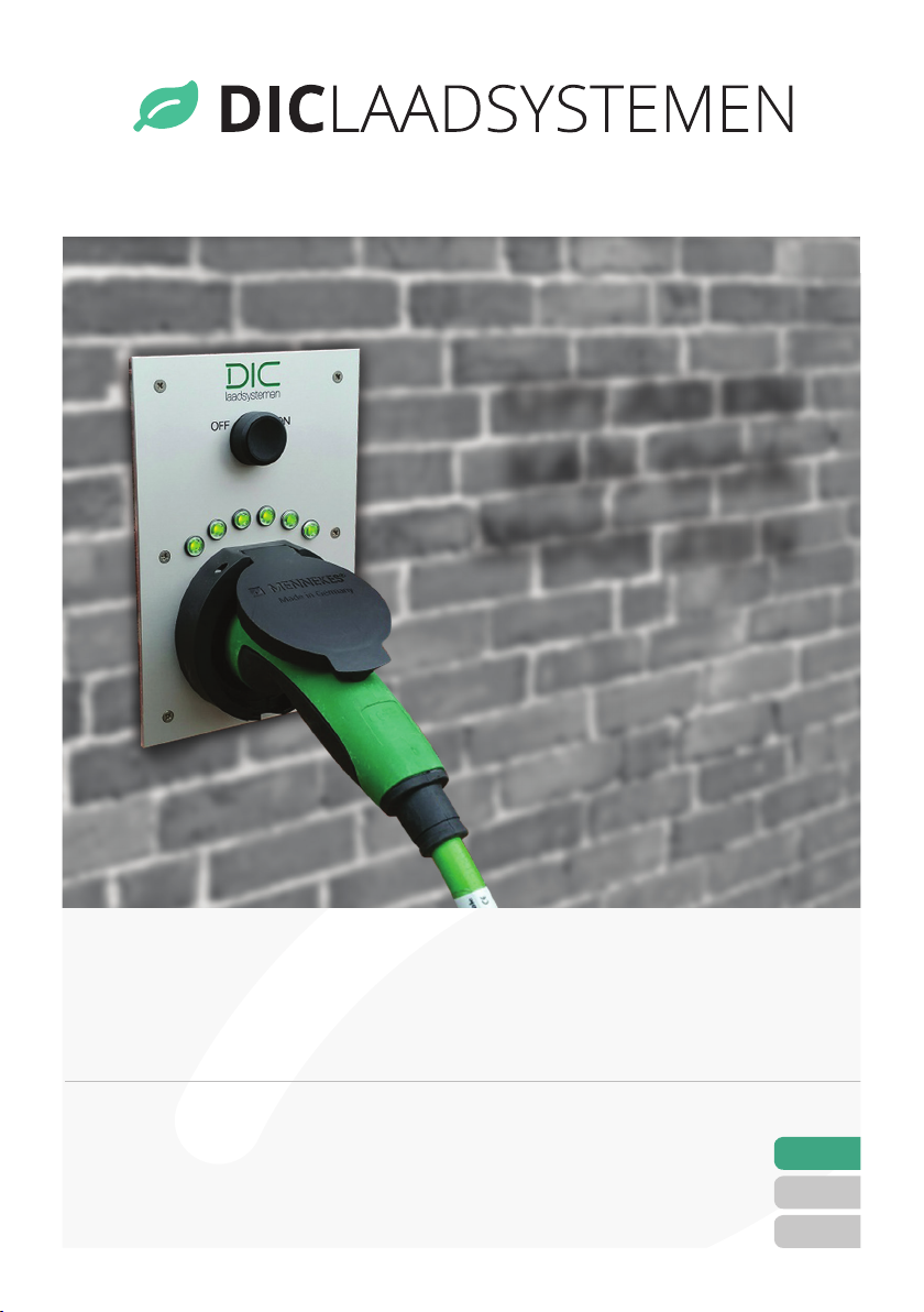
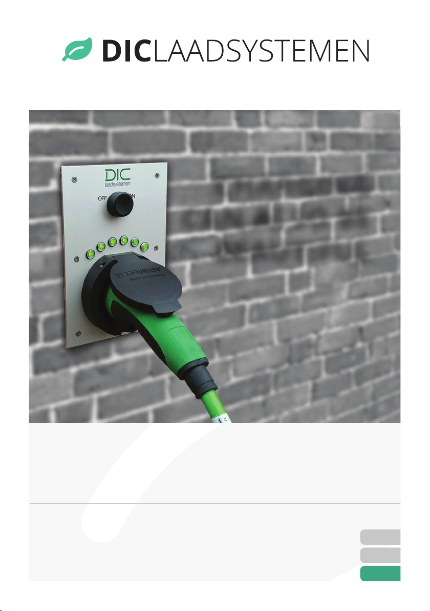
OPLADEN
KAN OOK
MOOI ZIJN
www.diclaadsystemen.nl
Plug and Charge 3,7kW 230V / 11kW 400V
NL
|01
DE |08
EN|15
ALUMINIUM INBOUW
OPLAADPUNT MONTAGE EN GEBRUIK
HANDLEIDING

www.diclaadsystemen.nl
2
NL
DE
EN
INHOUDSOPGAVE
Inbouw oplaadpunt plug and charge.
1 Veiligheidsvoorschriften 04
2 Montage plan 04
2.1 Aansluitschema 05
3 In bedrijf stellen 06
3.1 Voeding inschakelen 07
3.2 Testen 07
4 Laadpunt activeren 07
www.diclaadsystemen.nl
3
NL
DE
EN
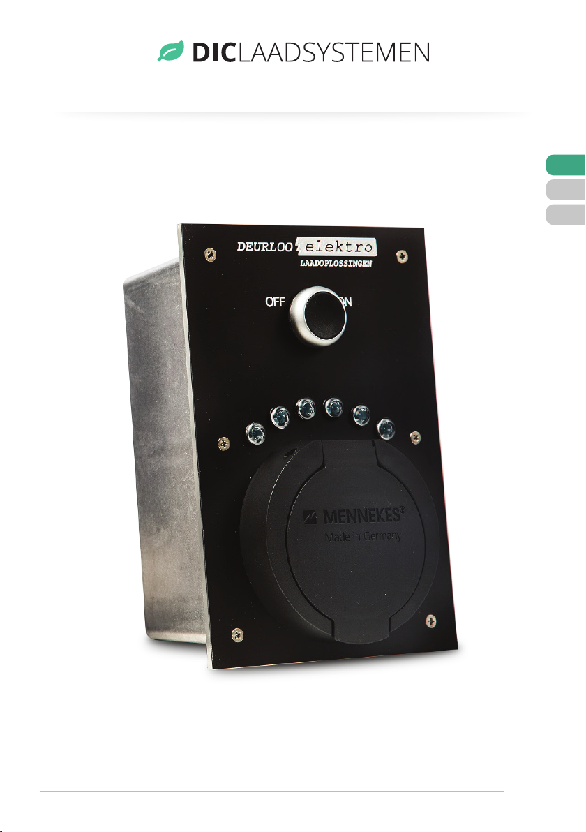
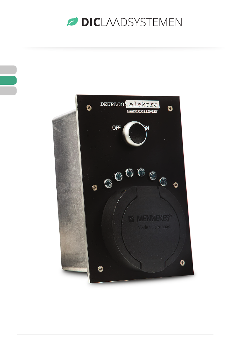
Ook in zwart leverbaar.

www.diclaadsystemen.nl
4
NL
DE
EN
1 VEILIGHEIDSVOORSCHRIFTEN
Lees eerst goed de bijgeleverde documentatie. Houd er goed rekening mee dat u
aan een elektrische installatie werkt!
Zorg tijdens de montage van het inbouw oplaadpunt dat er géén spanning
aanwezig is. Het laadstation is volgens de laatste geldende voorschriften
ontworpen, volgens de richtlijnen IEC 61851.
Veilige montage mag uitsluitend door een gediplomeerde monteur van een erkend
bedrijf plaatsvinden. Bij verkeerd gebruik kan een gevaarlijke situatie ontstaan.
De complete lader bestaat uit 2 delen:
Deel 1: De inbouw unit.
Deel 2: De controlebox inclusief 4 meter stuurstroom kabel.
2 MONTAGE PLAN
Bepaal de juiste locatie voor het oplaadpunt. Teken de voorzijde af op de wand, houd
er rekening mee dat de aluminium inbouw doos taps loopt. Zaag de afgetekende
uitsparing netjes uit (zie foto 1).
Het inbouw deel en de controle box moeten worden verbonden d.m.v. 2 kabels,
1 stuurstroom kabel van maximaal 4 meter welke is meegeleverd en een hoofdstroom
kabel bijvoorbeeld een ymvk kabel 5 x 2,5mm2.
Voor een 3,7kW aansluiting is een kabel minimaal 3 x 2,5mm2nodig. Voor een 11KW
aansluiting is een kabel minimaal 5 x 2,5mm2nodig. Voer de 2 kabels in door de
wartels en draai deze goed aan. Boor in het inbouw deel op de juiste plaats de
gaten waar mee deze unit wordt gemonteerd, (zie foto 2) houd bij de montage
rekening met de hoogte van de rubberen afdichting welke is meegeleverd (zie
foto 3). Boor gaten voor de meegeleverde pluggen 6 mm in de wand.
Sluit de contactdoos, vergrendel motor en led lamp nu aan volgens het aansluit-
schema (pagina 5).

www.diclaadsystemen.nl
5
NL
DE
EN
2.1 Aansluitschema
Foto 1 - uitsparing zagen Foto 3 - bevestig de rubberen afdichting
Foto 2 - boor de gaten
Laadpuntzijde Kabelzijde Omschrijving
1 Paars Paars CP
2 Paars Roze CP
3 Geel Geel PP
4 Blauw-1 Rood Motor
5 Blauw-2 Wit Motor
6 Blauw-3 Blauw Motor
7 Wit Zwart Puls drukknop
8 Wit Grijs Puls drukknop
9 Groen Groen Led +
10 Grijs Rood/blauw Led –

www.diclaadsystemen.nl
6
NL
DE
EN
Stuurstroom kabel CY 12 x 0,75mm2maximale
lengte 4 meter. Voedingskabel 5 x 2,5mm2
Ymvk of een grondkabel 4x2,5mm2 Ymv-kas.
Ook bij een 3,7kW model bij voorkeur een kabel
aanleggen met een 3 Fase nul en aarde.
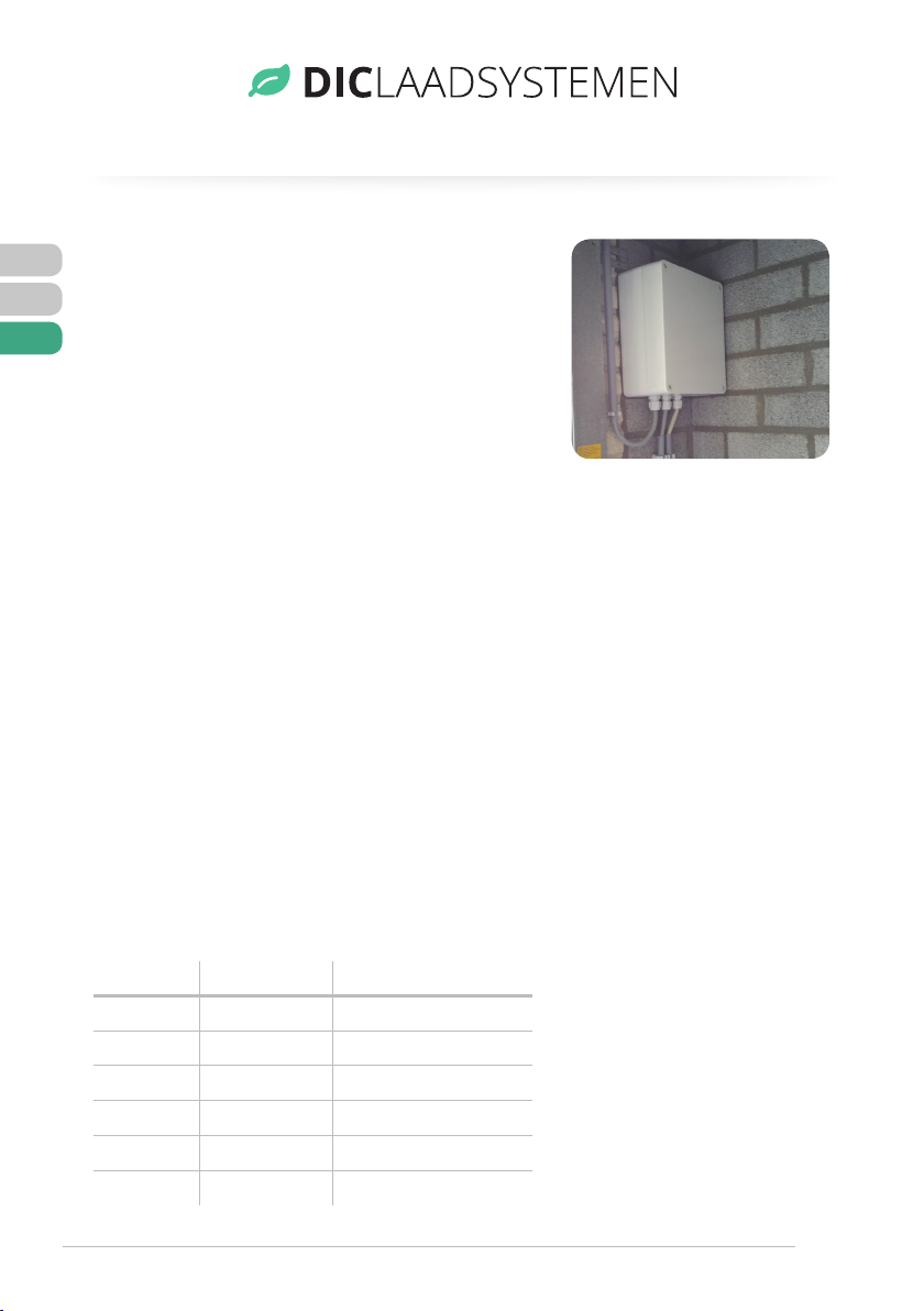
Monteer de controle box (foto 4).
3 IN BEDRIJF STELLEN
De voedingskabel van het inbouw laadpunt aansluiten achter een aparte automaat en
een aardlekschakelaar van 16 Ampére welke uitsluitend voor het laadpunt gebruikt
wordt.
Bij het gebruik van een 11kW model voor een Renault Zoë gebruik een type B of
EV aardlekschakelaar. Monteer de controle box binnen een afstand van maximaal
4 meter van het inbouw laadpunt. Sluit de voedingskabel aan op de klemmen L1,
L2, L3, N en aarde. Bij een 230v 3,7kW uitvoering blijven L2 en L3 vrij.
Sluit de voedingskabel met L1, L2, L3, N welke aangesloten zit aan het laadpunt
rechtstreeks aan op de relais. De Nul zit rechts van de Fase draden. Sluit vervolgens
de stuurstroom kabel aan:
Stuurstroom beveiliging 2A glaszekering.
Foto 4 - montage controle box
Klem Draad kleur Omschrijving
1 Paars CP
2 Roze CP
3 Geel PP
4 Rood Motor
5 Wit Motor
Klem Draad kleur Omschrijving
6 Blauw Motor
7 Zwart Puls drukknop
8 Grijs Puls drukknop
9 Groen Led +
10 Blauw/rood Led –
www.diclaadsystemen.nl
7
NL
DE
EN
3.1 Voeding inschakelen
Schakel de voeding pas in wanneer alle bedrading is aangesloten.
3.2 Testen
Plug de testkabel in het laadpunt met een verbruiker erin.
4 LAADPUNT ACTIVEREN
Activeer het laadpunt met de drukknop of sleutel schakelaar.
Groen: Laadpunt laad en de stekker is vergrendeld.
Verkoop via:
inter BÄR GmbH + Co. KG,
Hälverstraße 43, 58579 Schalksmühle, Germany,
phone +49 (0)2355 893-0
Foto 4 - montage controle box

ALUMINIUM EINBAU-
LADESTATION MONTAGE- UND
GEBRAUCHSANWEISUNG
AUFLADEN
KANN AUCH
SCHÖN SEIN
www.diclaadsystemen.nl
Plug and Charge 3,7 kW 230 V / 11 kW 400 V
NL
|01
DE |08
EN|15
www.diclaadsystemen.nl
9
NL
DE
EN
INHALTSVERZEICHNIS
Einbau-Ladestation Plug and Charge.
1 Sicherheitshinweise 11
2 Montage Plan 11
2.1 Anschlussplan 13
3 Inbetriebnahme 13
3.1 Einschalten der Stromversorgung 14
3.2 Prüfung 14
4 Aktivieren der Einbau-Ladestation 14
www.diclaadsystemen.nl
10
NL
DE
EN
Auch in schwarz lieferbar.

www.diclaadsystemen.nl
11
NL
DE
EN
1 SICHERHEITSHINWEISE
Bitte lesen Sie zuerst die Bedienungsanleitung sorgfältig durch.
Achten Sie darauf, dass bei der Installation der Ladestation keine Spannung
anliegt.
Die Ladestation wurde nach den neuesten gültigen Vorschriften, gemäß IEC 61851,
ausgelegt.
Die sichere Montage darf nur von einem qualifizierten Elektriker eines
zugelassenen Unternehmens durchgeführt werden. Unsachgemäße Verwendung
kann zu Lebensgefahr führen.
Die komplette Einbau-Ladestation besteht aus 2 Teilen:
Teil 1: Die Einbau-Einheit
Teil 2: Der Schaltkasten inklusive 4 Meter Steuerstromkabel
2 MONTAGEPLAN
Ermitteln Sie den richtigen Standort für die Ladestation. Markieren Sie die Vorderseite
an der Wand, beachten Sie, dass die Aluminium-Unterputzdose konisch ist. Schneiden
Sie den Ausschnitt sauber aus (siehe Foto 1).
Die Einbau-Einheit und der Schaltkasten müssen mit 2 Kabeln, einem mitgelieferten
Steuerstromkabel von maximal 4 Metern und einem Hauptstromkabel, z.B. einem
YMVK-Kabel 5 x 2,5 mm², verbunden werden.
Für einen 3,7 kW-Anschluss ist ein Kabel von mindestens 3 x 2,5 mm² erforderlich. Für
einen 11 kW-Anschluss ist ein Kabel von mindestens 5 x 2,5 mm² erforderlich. Führen
Sie die beiden Kabel durch die Buchsen und ziehen Sie sie gut an. Bohren Sie die
Löcher in das Einbauteil an der richtigen Stelle, um dieses Gerät zu montieren, (siehe
Bild 2) halten Sie die Höhe der Gummidichtung (siehe Bild 3) in der Montageberech-
nung ein. Bohren Sie Löcher für die mitgelieferten Dübel 6 mm in die Wand.
Schließen Sie nun Buchse, Verriegelung und LED-Leuchte gemäß Schaltplan
(Seite 5) an.

www.diclaadsystemen.nl
12
NL
DE
EN
Foto 1 - Aussparüng sägen Foto 3 - Befestigung der Gummidichtung
Foto 2 - Bohren Sie die Löcher
Ladepunkt-Seite Kabel-Seite Beschreibung
1 Lila Lila CP
2 Lila Rosa CP
3 Gelb Gelb PP
4 Blau-1 Rot Verriegelung
5 Blau-2 Weiß Verrigelung
6 Blau-3 Blau Verriegelung
7 Weiß Schwarz Impulstaster
8 Weiß Grau Impulstaster
9 Grün Grün LED +
10 Grau Rot/blau LED -

www.diclaadsystemen.nl
13
NL
DE
EN
2.1 Anschlussplan
Steuerstromkabel CY 12 x 0,75 mm² maximale
Länge 4 Meter. Netzkabel 5 x 2,5 mm² YMVK oder
ein Erdungskabel 4 x 2,5 mm² YMVK-AS. Auch für
ein 3,7 kW Modell ist es vorzuziehen, ein Kabel
mit einem 3-Phasen-Neutralleiter und Erde zu
installieren.
Montieren Sie den Schaltkasten.
3 INBETRIEBNAHME
Schließen Sie das Netzkabel der eingebauten Ladestation hinter einem separaten
Trennschalter und einem 16 Ampere FI-Schutzschalter an, der ausschließlich für die
Ladestation verwendet wird.
Wenn Sie ein 11 kW-Modell für einen Renault Zoe verwenden, verwenden Sie einen
Fehlerstromschutzschalter vom Typ B oder EV. Montieren Sie den Schaltkasten in
einem Abstand von max. 4 Metern von der eingebauten Ladestation. Schließen Sie
das Netzkabel an die Klemmen L1, L2, L3, N und Erde an. Bei einer 230 V 3,7 kW
Version bleiben L2 und L3 frei.
Verbinden Sie das Netzkabel mit L1, L2, L3, N, das mit der Ladestation direkt mit
den Relais verbunden ist. Der Nullpunkt befindet sich auf der rechten Seite der
Phasenleiter. Schließen Sie dann das Steuerstromkabel an:
Steuerstromschutz 2 A Glassicherung.
Foto 4 - Montage Schaltkasten
Klemme Drahtfarbe Beschreibung
1 lila CP
2 rosa CP
3 gelb PP
4 rot Verriegelung
5 weiß Verriegelung
Klemme Drahtfarbe Beschreibung
6 blau Verriegelung
7 schwarz Impulstaster
8 grau Impulstaster
9 grün LED +
10 blau/rot LED -

www.diclaadsystemen.nl
14
NL
DE
EN
3.1 Einschalten der Stromversorgung
Schalten Sie die Stromversorgung erst dann ein, wenn alle Kabel
angeschlossen sind.
3.2 Prüfung
Stecken Sie die Messleitung mit einem Verbraucher in die Ladestation.
4 AKTIVIEREN DER LADESTATION
Aktivieren Sie die Ladestation mit dem Druckknopf oder Schlüsselschalter.
Grün: Die Ladestation lädt und der Stecker ist verriegelt.
Vertrieb über
inter BÄR GmbH + Co. KG
Hälverstraße 43, 58579 Schalksmühle, Germany
Tel. +49 (0)2355 893-0
ALUMINIUM BUILT-IN
CHARGING STATION
MOUNTING AND OPERATING INSTRUCTIONS
CHARGING
CAN ALSO BE
BEAUTIFUL
www.diclaadsystemen.nl
Plug and Charge 3,7 kW 230 V / 11 kW 400 V
NL
|01
DE |08
EN|15
www.diclaadsystemen.nl
16
NL
DE
EN
TABLE OF CONTENTS
Built-In Charging Station.
1 Safety instructions 18
2 Mounting Plan 18
2.1 Wiring diagram 20
3 Implementing Built-In Charging Station 20
3.1 Switching on the power supply 21
3.2 Testing 21
4 Activating Built-In Charging Station 21

www.diclaadsystemen.nl
17
NL
DE
EN
Also available in black.

www.diclaadsystemen.nl
18
NL
DE
EN
1 SAFETY INSTRUCTIONS
Please read this operating instructions carefully first.
Make sure that no voltage is present during the installation of the charging station.
The charging station has been designed in accordance with the most recent
regulations in force, in accordance with IEC 61851.
Safe assembly may only be carried out by a qualified electrician from an approved
company. Improper use can lead to danger of life.
The Built-In charging station consists of 2 parts:
Part 1: The built-in unit
Part 2: The control box including 4 meter control current cable
2 MOUNTING PLAN
Determine the correct location for the charging point. Mark the front side on the
wall, note that the aluminium flush-mounted box is tapered. Saw out the cut-out
neatly (see photo 1).
The built-in unit and the control box must be connected by means of 2 cables, 1
control current cable of maximum 4 meters which is included and a main current
cable for example a ymvk cable 5 x 2.5 mm².
For a 3.7 kW connection, a cable of at least 3 x 2.5 mm² is required. For an 11 kW
connection, a cable of at least 5 x 2.5 mm² is required. Feed the 2 cables through
the bushings and tighten them properly. Drill the holes in the built-in part at the
right place to mount this unit, (see picture 2) keep the height of the rubber seal
(see picture 3) in the mounting calculation. Drill holes for the supplied plugs 6 mm
in the wall.
Now connect the socket, locking mechanism and LED light according to the wiring
diagram (page 5).

www.diclaadsystemen.nl
19
NL
DE
EN
2.1 Wiring diagram
Photo 1 - Sawing a cutout Photo 3 - Attaches the rubber seal
Photo 2 - Drill the holes
Charging point side Cable side Description
1 Purple Purple Cp
2 Purple Pink Cp
3 Yellow Yellow Pp
4 Blue-1 Red Locking mechanism
5 Blue-2 White Locking mechanism
6 Blue-3 Blue Locking mechanism
7 White Black Pulse push button
8 White Grey Pulse push button
9 Green Green Led +
10 Grey Red/blue Led -
www.diclaadsystemen.nl
20
NL
DE
EN
Control current cable CY 12 x 0.75 mm²
maximum length 4 meters. Power cable 5 x
2.5 mm² YMVK or a ground cable 4 x 2.5 mm²
YMVK-AS. Also for a 3.7 kW model it is preferable
to install a cable with a 3 Phase neutral and earth.
Mounting the control box.
3 IMPLEMENTING
Connect the supply cable of the built-in charging station behind a separate circuit
breaker and a 16 Ampere earth leakage circuit breaker which is used exclusively for
the charging station.
When using an 11 kW model for a Renault Zoe, use a type B or EV earth leakage circuit
breaker. Mount the control box within a distance of max. 4 metres from the built-in
charging station. Connect the power cable to terminals L1, L2, L3, N and earth. With a
230 V 3.7 kW version, L2 and L3 remain free.
Connect the power cable with L1, L2, L3, N which is connected to the charging station
directly to the relays. The Zero is on the right side of the Phase wires. Then connect
the control current cable:
Photo 4 - Mounting the
control box
Terminal Wire colour Description
1 purple Cp
2 pink Cp
3 yellow Pp
4 red Locking mechanism
5 white Locking mechanism
6 blue Locking mechanism
Table of contents
Languages:


LG Standart manual")
