Atek QUEST TECHNOLOGIES M-7B User manual

TABLE OF CONTENTS
MODEL M-7B NOISE DOSIMETER …………………………………………… 1
General Description ………………………………………………………….. 1
Specifications …………………………………………………………………. 3
Controls and Display ………………………………………………………. 5
PRINCIPLES OF OPERATION ………………………………………………… 6
General ………………………………………………………………………… 6
Weighting Characteristics ……………………………………………………. 6
Microphone Characteristics ………………………………………………… 7
Internal Electrical Noise ……………………………………………………… 8
115 dB (A) Indicator ………………………………………………………….. 8
Memory ………………………………………………………………………… 8
OPERATING PROCEDURE …………………………………………………… 8
Battery Test …………………………………………………………………… 8
Battery Replacement ………………………………………………………… 8
Taking a Measurement ……………………………………………………… 9
Noise Exposure Conversion Chart ………………………………….……… 9
Effects of Operator's Presence ……………………………………….…….. 10
Considerations of Measurement and Accuracy …………………………… 12
Use with Windscreen ………………………………………………………. 13
CALIBRATION AND MAINTENANCE ……………………………………….. 16
ACCESSORIES ………………………………………………………………… 16
SERVICE POLICY ………………………………………………………………. 17
Service Policy ………………………………………………………………… 17
NOTE
Your new M-7B Dosimeter fully meets the require-
ments of the OSHA Hearing Conservation Amend-
ment and has the following capabilities:
1. 80-140dBA dynamic range.
2. 30dB crest factor for impulsive
noise
measurements.
3. User-selectable threshold of 80 or 90dB
with jumper (located under the battery
compartment on the circuit board.)
Advanced Test Equipment Rentals
www.atecorp.com 800-404-ATEC (2832)
®
E
s
t
a
b
l
i
s
h
e
d
1
9
8
1

MODEL M-7B NOISE DOSIMETER
GENERAL DESCRIPTION
The Quest Model M-7B Noise Dosimeter is a lightweight, pocket-sized self-
contained instrument that measures cumulative exposure to noise. The unit is
primarily intended to measure noise exposure in accordance with the
Occupational Safety and Health Administration (OSHA) noise criterion based
on a permitted exposure time doubling for each 5 decibel lowering in the "A"
scale weighted sound. This is referred to as a 5 dB exchange ratio. The
maximum OSHA noise levels expressed in dB(A) vs. exposure time are shown
in the following table.
In industrial environments where noise levels vary continually, manual
computation of noise dose involves tedious day-long measurement with a
sound level meter and stop watch in order to determine the noise exposure as
computed by the formula:
where D is noise dose, C is the actual duration of time at a given noise level,
and T is the maximum exposure time per day at that noise level as shown in
the OSHA table above. The M-7B noise dosimeter automatically performs the
entire task of measuring, timing, and computing the noise dose. The computed
dose is read directly at the end of the measurement period as the percentage of
the daily allowable dose.
The M-7B measures and accumulates noise and produces a continuous
reading of the percentage of the allowable exposure to which the wearer has
been subjected. In addition, the unit can be used for short term sample tests
with the readout quickly converted both to the equivalent dB(A) sound level and
to the maximum time a worker can be in the noise environment. Refer to
Conversion Chart, page 11.
Being a small device permits a person to wear it in a shirt pocket or on a
belt. The microphone is clipped to the shirt collar near the ear, thereby
perceiving and accumulating approximately the same dosage as the ear. The
unit can also be mounted on a tripod for an area survey.
The noise accumulated over the day or test period is read on a five digit
L.E.D. display by depressing the READ button. The display reads in percent of
the daily exposure allowed by OSHA. Readings extend from 000.01 to 999.99
and change in .01 increments. A reading of 100.00 indicates an exposure of
100% (OSHA criterion number 1) and is the maximum allowable exposure for
one day. If the exposure readout exceeds 999.99, the display will go into a
blanked mode where only the decimal point will light. Such an indication thus
means the exposure limit was exceeded.
Noise levels above 115 dB(A) activate an internal electronic latch and are
indicated by a small light below the exposure display when the READ button is
depressed. A one second time delay prevents activation of the latch by impulse
noises.

The M-7B on delivery, is always calibrated to the requirements of the
prevailing OSHA law unless otherwise indicated by the user. The unit can,
however, be set to other range and threshold levels, and can also be converted
to a Model M-8B Noise Dosimeter which is based on a 3 dB equal energy
exchange ratio. Minor internal changes are required for this conversion.
The M-7B can be used in virtually all environments: industry, construction,
mining, transportation — anywhere there is noise.
SPECIFICATIONS
Noise Level Range: 80 to 130 dB(A) range ref. 20µPa. Threshold and 8-
hour criteria level are set to prevailing OSHA requirements or to special user
needs.
Exposure Readout: Integral 5-digit L.E.D. display (to 999.99%).
Criterion Level: 90 dB(A) for 8 hours produces a 100% readout. Can be
modified to other criterion levels as necessary for application.
Threshold Level: 80 dB. Can be changed to 90 dB with jumper. Can be
adjusted to other levels.
Exchange Rate: 5 dB time doubling per OSHA requirements.
Crest Factor: 30 dB within dynamic span.
Dynamic Span: 80 to 140 dB.
Frequency Response: "A" Scale, 20 Hz to 10 kHz.
Standards: ANSI S1.25 -1978 Type 2.
Detector: True RMS, SLOW response.
115 dB(A) Indication: Indicates reception of sound level above 115 dB(A).
Can be adjusted to other limits.
Accuracy: At 110 dB(A), 1 kHz input, 23°C, atmospheric pressure of 760
mmHg: counter reading is within ±7% of theoretical accumulation. This
corresponds to ±0.5 dB.
Linearity: From Low Threshold Cut-Off to 130 dB, ±0.5 dB (measured at 1
kHz with reference to 110 dB).
Microphone: PZT ceramic, 8 mm diameter, 30 inch cable with spring clip for
attaching microphone to shirt collar.
Calibration: External calibration adjustment available. May use Model CA-32
Timed Sound Calibrator, Model CA-12B Sound Calibrator, Model CA-15B
Calibrator, or other calibrators that will adapt to the 8 mm microphone. This
calibration adjustment is meant for minor adjustments only (±1 dB). A more
thorough internal calibration is necessary for larger adjustments.
Temperature Range: Operating within ±1 dB, -10°C to +50° C Storage: -40°
C to +60° C. (battery removed)
Operating Humidity: 0% to 95% Relative Humidity.
Magnetic Field Effect: Dosimeter will accumulate exposure equal to a level
less than 80 dB(A) in a magnetic field of 4000 A/M (50 oersteds) at 50 or 60 Hz.
If field effects and actual noise are below threshold cut off, no accumulation will
result. A 400 A/M field induces the equivalent of 50 dB noise signal.
Vibration Effects: Vibration of the M-7B without the microphone has
essentially no effect on the dosimeter accuracy at an acceleration of 0.1 g.
However, the microphone will act as an ac-celerometer if vibrated. A sinusoidal
acceleration of 0.1 g at 500 Hz in a direction perpendicular to the plane of the
microphone diaphragm (WORST CASE) will generate an equivalent sound
level of approximately 85 dB. Frequencies below 500 Hz with the same ac-
celeration have less effect due to the "A" scale weighting.
Battery: One 9 Volt Alkaline battery (NEDA 1604) will provide power for 100
hours under normal operating conditions. Low temperature reduces battery life:
approximately 70 hours at 30°F; 25 hours at 0°F.
Battery Status Indicator: When pressing READ button, the BATT light in the
display window indicates sufficient battery power for 8 hours of operation.
Belt/Pocket Clip: Holds the dosimeter in a shirt pocket or on a belt.
Tripod Mount: Threaded insert provided on the Belt-Pocket Clip will accept a
standard 1/4-20 tripod mounting screw.
Size: 4-3/4 x 2-1/2 x 1-1/4 inches. Weight: 9 ounces (including battery).
Construction: Solid state integrated circuitry in a rugged aluminum housing.

Conversion Capability: Should there ever be a requirement or OSHA law
change, the M-7B can be converted from 5 dB to a 3 dB or 4 dB exchange
ratio.
CONTROLS AND DISPLAY
ON-OFF Switch — A 2-position slide switch that turns the unit on and off but
does not destroy the memory. It does reset the 115 dB(A) latch. After turning
the M-7B on, wait for at least 10 seconds before using or calibrating it to let the
unit stabilize.
READ Button — A push button that illuminates the 5-digit display, the 115
dB(A) indicator (if latched on), and the battery status indicator (if battery has
sufficient power for 8 hours of operation).
RESET Button — A recessed push button that resets the 5-digit display
when pressed simultaneously with the READ button.
Calibration Adjustment -- A screwdriver adjustment (located near the
microphone cable outlet) that varies the amplifier output.
Display -- The L.E.D. display contains the 115 dB(A) indicator light, the
battery (BATT) indicator light, and a 5-digit percentage readout of exposure.
Threshold Setting — 80 or 90 dB, user selectable with jumper wire located
within the battery compartment on the circuit board.
PRINCIPLES OF OPERATION
General
The M-7B Noise Dosimeter uses a small omnidirectional ceramic
microphone buffered by a high impedance FET input stage. The electronics
utilize low power integrated circuitry for long battery life and maximum stability
and reliability over a wide range of environmental conditions. A block diagram
of the M7-B is shown in Figure 3.
Weighting Characteristics
In accordance with OSHA requirements, the M-7B has an "A" scale
weighting characteristic as shown in Figure 4. Since the human ear does
not respond well to low frequencies, the "A" weighting electronically
designed into the dosimeter measures noise in a similar manner as the ear
hears the sound or is affected by it. Therefore, the exposure or dosage
reading on the M-7B accumulates at a slower rate with low frequency

noise than with high frequency noise at the actual decibel level.
Microphone Characteristics
The microphone used on the M-7B dosimeter is a Model 1845 ceramic
microphone designed for use in sound level measuring instruments. An integral
FET amplifier and controlled acoustical construction provide the transduction
sensitivity level, frequency range, and flat frequency response necessary for
ANSI S1.4-1983 Type 2 sound level meter requirements. Overall diameter is 8
mm. Typical sensitivity is 70 dB below 1 volt per microbar measured at 1 kHz.
Figure 5 is a diagram of typical microphone response.
Internal Electrical Noise
The internal electrical noise of the M-7B is equivalent to an acoustic level of
approximately 40 dB. With the dosimeter lower threshold set at 80 dB(A) or
higher, internal electrical noise thus has no effect on the reading.
115 dB(A) Indicator
When using the M-7B, if the microphone is exposed to more than 115 dB(A)
for a minimum of one second, the indicator circuitry will latch on, and the
indicator light will go on when the READ button is pressed. This indicator is
reset only when the M-7B is turned off for at least a few seconds and then
turned on again.
Memory
The memory consists of a CMOS counter that retains the accumulated
counts or an overflow indication of exceeding counter capacity. The memory
content is not lost by turning the power switch off. Only the removal of the
battery or use of the RESET button can erase the memory.
OPERATING PROCEDURE
The M-7B is designed to be worn as a personal monitor. However, the unit
also can be tripod-mounted and used as an area monitor. Before mounting the
M-7B, it should be checked to see that battery power is adequate and that the
unit is properly reset to zero. The unit should then be checked for calibration
accuracy before putting into service. The high readout resolution (counting in
0.01% increments) permits very rapid, accurate short term measurements and
also rapid calibration. If you use the dosimeter for an all-day measurement, the
two digits behind the decimal point become insignificant.
Battery Test
Turn unit ON. Press and hold READ button for 5 seconds. The 5-digit
display and the indicator light labeled BATT should light and remain on for at
least 5 seconds to indicate that the battery has sufficient power to operate the
M-7B for at least 8 hours. If not, replace battery. If the display is in the blanked
mode with only a decimal point lit, depress the RESET button while holding the
READ button. This will reset the counter to 000.00.
Battery Replacement
Loosen slotted captive screw from battery compartment. Lift the battery flap
to expose the battery. Be sure unit is turned off and then carefully remove the
battery from its cavity and unclip the connector. REPLACE WITH 9 VOLT
ALKALINE BATTERY ONLY!

Take care to observe polarity of battery and connector. Be sure a good
electrical connection has been made. Then replace the battery and the cover.
NOTE
When battery is connected, the counter memory can
come on in any state. Be sure to reset it before use.
Taking a Measurement
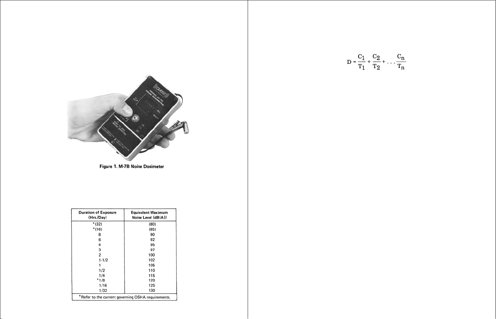
Turn the unit on. Be sure to reset the counter and the 115 dB(A) indicator,
and attach the M-7B to either the belt or the shirt pocket using the spring clip on
the case. If desired, the detachable security cover may be used to prevent
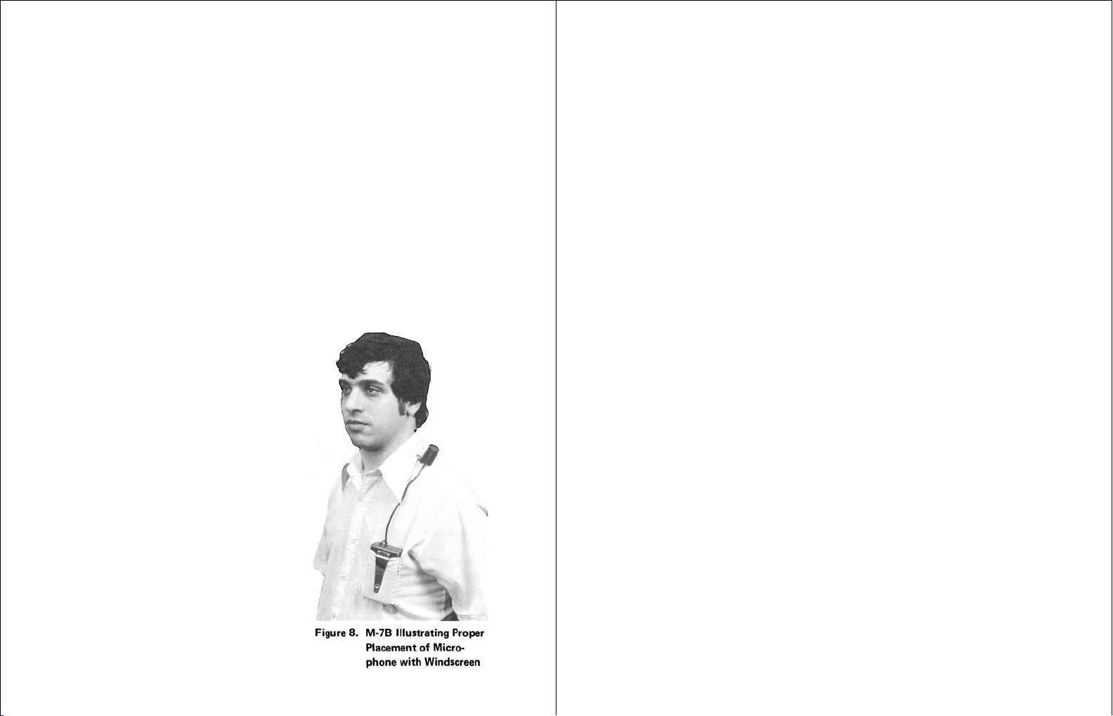
tampering with the dosimeter. Clip the microphone to the shirt or jacket collar
high on the shoulder. (Refer to "Effects of Operator's Presence", page 10).
Place the cable in the best position available, possibly under the shirt, to
prevent it from being entangled with other objects.
NOTE
If area noise rather than personal noise is to be monitored,
reset the counter and 115 dB(A) indicator and attach the M-7B
to a tripod using the 1/4-20 threaded insert on the spring clip.
Suspend the microphone away from solid surfaces, and at an
angle equivalent to random incidence (approximately 70° to
the direction of the sound source). With the unit turned ON, the
M-7B is now measuring and integrating noise levels between
the lower threshold limit and 140 dB(A) maximum.
Take the exposure measurement, either a short term sample or an all day
monitor, as needed. If noise levels vary considerably, monitor the noise for the
full work day.
At the end of the exposure period, depress the READ button. The noise
dose for the duration of the measurement period is displayed along with the
115 dB(A) indication (if 115 dB(A) was exceeded). Also, the BATT indicator
should light for a minimum of one second, indicating that the battery power was
sufficient during the measurement period.
After the data has been read, the unit can be turned off. This does not
destroy the count in the memory but does reset the 115 dB(A) latch. If the M-7B
will not be used again for a week or more, it is best to remove the battery to
prevent further drain.
Noise Exposure Conversion Chart
When the M-7B is used to take a measurement for the full work day, the
dosage for that day appears directly in the display. For example, if the reading
for 8 hours was 200.00 (200% of allowable
exposure), it would mean that the wearer had received twice the maximum
dosage for the day. If the measurement is taken for 4 hours of an 8 hour work
day, the counter should read less than 050.00 (50% of the allowable exposure)
to be within the specified limits. Regardless of the length of the work day, the
M-7B indicates the percentage of allowable noise that has been received up to
that time.
After taking a measurement for some determined time period, the readout
exposure can be converted to the equivalent dB(A) level for the entire time
period, and can also be used to determine the allowable exposure time per day
by using the Conversion Chart in Figure 6. This chart is also provided as a
handy separate slide rule "Noise Exposure Calculator" with each M-7B.
The Chart in Figure 6 is used to convert the dosimeter reading to both
Equivalent OSHA Exposure in dB(A) and to the Allowable Exposure Time per
Day in Hours. The chart is based on an allowable exposure of 90 dB(A) for 8
hours — which is indicated by a dosimeter reading of 100.00. In the example
above the dosimeter reading of 200.00 is converted by referring to the diagonal
line representing a measurement period of 8 hours. Find the intersection of this
line with the line representing a counter reading of 200.00. The vertical line
through this intersection indicates that the equivalent OSHA exposure, shown
at the top of the Chart, is 95 dB(A) and that the allowable exposure time per
day, shown at the bottom of the chart, is 4 hours.
Conversions for other counter readings and measurement periods are made
in a similar manner by using the appropriate counter reading and diagonal
measurement period line.
SHORT DURATION MEASUREMENTS can be taken if the noise level for
the period under measurement is representative of the entire day. Also, a
period of measurement should be long enough to accumulate a reading of at
least 000.50 to insure accuracy.
As another example, a measurement is taken for 5 minutes and the total
count accumulation is 005.60. Find the 5 minute period of measurement line on
the Conversion Chart. Next, locate the intersection of this diagonal line and the
005.60 counter reading at the left. The top of the Chart indicates the equivalent
dB(A) level is 102 dB(A), and the bottom of the Chart shows 1.5 hours is the
allowable exposure time per day.
Effects of Operator's Presence
Any object or surface can act as a reflector of sound. An operator or person
wearing the dosimeter is also a reflector and affects the microphone
performance. The M-7B is calibrated to read correctly with the microphone in a
random incidence sound field without the

presence of reflecting objects. Placing the microphone in a shirt pocket or in the
chest area could thus tend to produce large errors — as much as several
decibels. The best location is several inches above the person's head. In this
location the microphone can receive sound from all directions with essentially
no reflecting surfaces near enough to cause notable error. However, this
location is impractical. The most practical location — and the one
recommended — is the shirt collar, high on the shoulder and away from the
neck as far as practical.
If the dosimeter is mounted on a tripod and used as an area monitor, the
microphone should be suspended away from the tripod and M-7B chassis (see
Figure 7). It is recommended that a thin rod be used to hold the microphone
with the cable extended the full 30 inches. The microphone should be pointed
upward forming approximately a 70° angle with the horizontal direction of the
noise source.
Considerations of Measurement and Accuracy
The M-7B is intended to be used for fluctuating noise environments. The M-
7B or any other properly designed dosimeter should produce greater accuracy
in the measurement of exposure than any sound level meter method of
measurement and calculation. The dosimeter avoids the potential error created
by the human factor in trying to time and interpolate a moving meter needle.
Microphone location affects the instrument reading and has been discussed
under "Effects of Operator's Presence". It is important to place the microphone
near ear level at a location that minimizes body reflective and shielding effects.
Threshold discontinuity can cause notable differences in readings on
various dosimeters even with slightly different locations of the microphone
when the actual noise level is in and around the threshold point of the
dosimeter. When the noise is at or slightly below the threshold, the dosimeter
may or may not be accumulating. You could imagine a noise level at the
threshold where one device has just turned on and another where the unit was
just off. The first

would accumulate a sound while the second would not. This same problem
occurs with a sound level meter where the operator must make a judgment
whether the noise is just above or below the threshold.
If total accumulation of the dosimeter exceeds 10 times the permitted
dosage (just past a reading of 999.99), the unit readout will go into a blanked
condition with only the decimal point lit. This indicates that the limit of the
counter was exceeded, and thus prevents reading the dosimeter incorrectly
which would occur if the unit were recording noise the second time around on
the counter.
Peak noise levels exceeding 140 dB(A) will be internally "clipped" and act as
if they were 140 dB(A). However, since OSHA requirements limit noise to 115
dB(A), this upper limit is not likely to enter into the measurement. Actual peak
noise should be measured with a peak reading and hold meter such as the
Quest Model 215-35 Peak-Hold Meter.
Impulsive noise and noise with large crest factors. The M-7B accurately
measures impulsive noise with crest factors (peak to RMS ratio) of 30 dB within
a dynamic span of 80 to 140 dB.
Use with Windscreen
To prevent wind from blowing across
the microphone and causing an erroneous
measurement of sound level, the Model
WS-5 Windscreen (for 8 mm microphones)
should be used (see Figure 8). It is
recommended that the windscreen be
used at all times in that it helps support the
microphone in an upright position when
worn. It will also help protect the
microphone under dusty, oily, and humid
conditions. The windscreen is made of
reticulated polyurethane foam. The screen
is simply pushed onto the microphone
when needed. The acoustic attenuation
effect of the windscreen on the dosimeter
is very small and for all practical purposes
can be neglected. Maximum attenuation
occurs at high frequencies and is
approximately 0.5 dB at 8 kHz, .25 dB at 5
kHz, and 0 dB at frequencies below 2.5
kHz.
CALIBRATION AND MAINTENANCE
The M-7B should maintain its accurate calibration for many months of use.
However, to insure consistently accurate operation, it is recommended that the
unit be returned to the factory at least once a year for complete checkout and
calibration. The calibration standards for equipment in Quest's Laboratory are
traceable to the U.S. National Bureau of Standards.
For OSHA measurement, the M-7B should be checked daily with an
acoustic calibrator before being used. It is recommended that one of the Quest
calibrators, such as the CA-12B, CA-15B or CA-32 Field Sound Calibrators, be
used with the proper 8 mm microphone adapter.
IMPORTANT!!
The OSHA Hearing Conservation Amendment has not changed
the 90dB(A)-8 hour criterion. The amendment requires you now
look for a TWA for 8 hours of 85dB which is an exposure of 50%.
To properly calibrate the M-7B for the new OSHA Hearing
Conservation Amendment, follow the calibration procedure for
90dB(A)-8 hour criterion level.
NOTE
Because of the "slow" response time constant built into the M-
7B, a "trail-off" or decay or count rate can be noted in the
readout with the abrupt removal of a high level sound. This trail-
off is proper and can last for several seconds. The dose value
given in the following paragraphs includes this trail-off.
1. Using the Quest CA-32 single-level, single-frequency, precision
timed calibrator:
Place the 8 mm adapter into the CA-32. Then insert the M-7B microphone.
Holding the microphone firmly and squarely into the CA-32, turn the calibrator
so that the controls are facing upwards. Switch on the CA-32. Turn on the M-
7B, wait at least 10 seconds, and reset the count to 000.00. Press the
Calibrator START button. The 32 SEC. light will come on for exactly 32
seconds indicating the duration of the 110 dB output. When the light goes out,
press the READ button on the M-7B. For a 90 dB(A)-8 hour criterion level,
(OSHA), the readout should be between 001.64 and 002.15, based on a ±1 dB
tolerance, with 001.87 being exact. If the count is too high, turn the gain adjust
screw (near the microphone cable outlet) slightly counterclockwise. Then
recheck calibration.

2. Using the Quest CA-12B single-level, single frequency calibrator
(Optional):
Place the 8 mm adapter into the CA-12B. Then insert the M-7B microphone.
Be sure the microphone rests squarely on the inner rim. Turn on the M-7B and
the CA-12B. Wait 10 seconds for the M-7B to stabilize. Then, while using a
timing device such as a wrist watch or a stop watch, reset the M-7B to 000.00,
time for one minute for a 90dB(A)-8 hour criterion level, and turn off the
calibrator. At the end of the timed period the readout should be between 002.98
and 003.94, based on a ±1 dB tolerance, with 003.42 being exact. If the count
is too high, turn the gain adjust screw (near the microphone cable outlet)
slightly counterclockwise. If the count is too low, turn the screw slightly
clockwise. Then recheck calibration.
3. Using the Quest CA-15B multi-frequency calibrator (Optional):
The various frequency settings of this calibrator permit the operator to check
the M-7B at 125 Hz, 250 Hz, 500 Hz, 1 kHz, and 2 kHz. The M-7B incorporates
"A" scale weighting so that it responds to noise levels in a manner similar to the
human ear. See Figure 4. Thus when frequencies are changed, the M-7B count
rate also changes. The following table shows the acceptable range of counter
readings at each of the test frequencies.
To check the M-7B turn it on, wait at least 10 seconds, depress the READ
button, and reset the counter to zero. Turn the CA-15B Calibrator on to desired
frequency with the 8 mm adapter in the calibrator cavity. Place the M-7B
microphone into the calibrator cavity. When you are ready to time, switch on the
M-7B for exactly one minute, or 1/2 minute, as appropriate. At the conclusion of
the one minute test, pull the microphone out and away from the calibrator.
Read the M-7B exposure value and compare it with the readings in the
calibration table after the M-7B has stopped counting.
Calibrate the M-7B with the adjusting screw using the 1 KHZ preferred
frequency only. Then, the other frequency-dependent readings will fall within
acceptable limits. If they do not, then the unit should be more thoroughly
checked at the Quest Laboratory facility.
ACCESSORIES
MODEL WS-5 WINDSCREEN
Refer to page 13 for instructions on how to use the windscreen with the M-
7B microphone.
TRIPOD
Quest supplies two models of tripods for use with the M-7B as an area
monitor, with the model TP-2 being generally recommended. Figure 7 shows
the M-7B mounted on a tripod.
Closed Extended
Model Height Height
TP-1 20inches 55inches
TP-2 10inches 51inches

Service Policy
The Quest product you have purchased is one of the finest acoustic instru-
ments available. It is backed by our full one year warranty which seeks com-
plete customer satisfaction. This is your assurance that you can expect prompt
courteous service for your equipment from the entire Quest service organiza-
tion.
Should your Quest equipment need to be returned for repair or recalibra-
tion, please contact the Service Department at (800)245-0779 (USA) or Fax
(262)567-4047 for a Return Authorization Number. The RA number is valid for
30 days, and must be shown on the shipping label and purchase order/cover
letter. If you are unable to return instruments in that time call for a new RA num-
ber. Send it prepaid and properly packed in the original shipping carton directly
to Quest Technologies, 1060 Corporate Center Drive, Oconomowoc, WI 53066
U.S.A.
Repair or replacement work done under warranty will be performed free of
charge, and the instrument will be returned to you prepaid. Your copy or a
photocopy of the Quest Registration Card will serve as proof of warranty should
the factory require this information.
If for any reason you should find it necessary to contact the factory regard-
ing service or shipping damage, please direct your calls or letters to the atten-
tion of the Service Manager, Quest Technologies, (262) 567-9157 or (800) 245-
0779. Office hours are from 7 AM to 6 PM (Central Standard Time) Monday
through Friday.
For service or recalibration outside the U.S.A., please contact your local
Quest Dealer or fax Quest U.S.A. at 1-262-567-4047.
Table of contents
Other Atek Measuring Instrument manuals
Popular Measuring Instrument manuals by other brands

Cardinal
Cardinal 225 Installation, Set-Up and Operation Manual

Blue-White
Blue-White F-440 quick start guide

Absolute Process Instruments
Absolute Process Instruments Cecomp F16AD instructions

Datcon
Datcon PQRM5300 33 U I Series instruction manual

Keller
Keller LEO2-Ei manual

CONDTROL
CONDTROL MicroX user manual