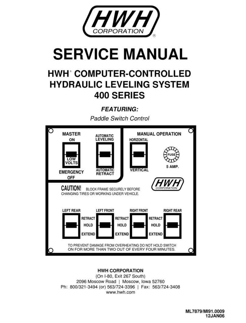
ATEMAG Control 4.0 User manual

Translation
ORIGINAL MANUAL
ATEMAG Control 4.0

2 von 13 Translation Original Manual ATEMAG Control 4.0 06.09.2019 I00
Table of content
1General.............................................................................................................................................3
1.1 About the operation manual..............................................................................................................3
1.1.1 Release.............................................................................................................................................3
1.1.2 Requirement .....................................................................................................................................3
1.1.3 Availability.........................................................................................................................................3
1.2 Used description in this operating manual........................................................................................3
1.2.1 Procedure of action...........................................................................................................................3
1.2.2 Illustration of safety indications.........................................................................................................3
1.2.3 Applied symbols................................................................................................................................4
1.2.4 Indication...........................................................................................................................................4
1.3 Guarantee and liability......................................................................................................................4
1.3.1 Wireless functionality disclaimer.......................................................................................................4
1.4 Information about manufacturer........................................................................................................4
1.5 Product observation..........................................................................................................................4
1.6 Content of delivery............................................................................................................................4
2General Safety Instruction..............................................................................................................5
2.1 Appropriate Application.....................................................................................................................5
2.2 Remaining risk..................................................................................................................................5
2.3 Personnel requirements....................................................................................................................5
3Explanation of the chip unit...........................................................................................................5
3.1 Main components of the chip unit.....................................................................................................5
4Operation of the chip unit...............................................................................................................5
4.1 Operating modes ..............................................................................................................................6
4.2 LED display.......................................................................................................................................6
4.3 Battery replacement..........................................................................................................................7
5Communication ...............................................................................................................................8
5.1 Cloud functionality.............................................................................................................................9
5.1.1 Call up Cloud and log in....................................................................................................................9
5.1.2 Call up aggregate..............................................................................................................................9
5.1.3 Call up and download history and telemetry data...........................................................................10
6Assembly and connection............................................................................................................11
6.1 Retrofit aggregate...........................................................................................................................11
7Dysfunction....................................................................................................................................12
8Disposal..........................................................................................................................................12
9Extract from the EC declaration of conformity ..........................................................................12

General
Translation Original Manual ATEMAG Control 4.0 06.09.2019 I00
3 von 13
1 General
1.1 About the operation manual
1.1.1 Release
Status of the manual: ...............................................................................06.09.2019
Revision index: .......................................................................................................00
1.1.2 Requirement
We require that the operator is trained in the safe operation of the chip unit and has read and understood
this operating instruction.
1.1.3 Availability
Always keep the manual available to all persons who work with or on the chip unit.
1.2 Used description in this operating manual
1.2.1 Procedure of action
Procedures of action are marked as triangles in sequence of execution. The results of procedure are
marked with a check mark. Example:
Loosen cylindrical screw M5 (2).
Arrestor bolt slides into the driving groove of the machine.
1.2.2 Illustration of safety indications
Safety indications are always marked with a signal word and sometimes additional marked with a danger
specific symbol (see Chapter 1.2.3):
DANGER!
Direct danger!
Ignoring this indication severe injuries or death is the consequence!
WARNING!
Possibly danger situations!
Ignoring this indication result in severe injuries or death!
ATTENTION!
Possibly danger situation!
Ignoring this indication cause medium or light injuries!
CAUTION!
Possibly danger situation!
Ignoring this indication cause damage to property or pollution!

General Safety Instruction
4 von 13 Translation Original Manual ATEMAG Control 4.0 06.09.2019 I00
1.2.3 Applied symbols
The followed symbols are used in this manual:
Warning symbol
Environmentally hazardous substance!
Magnets can affect the function of pacemakers and implanted defibrillators!
Corrosive substances!
Tab 1: Warning symbol
1.2.4 Indication
Indication:
Describes general information and recommendation.
1.3 Guarantee and liability
Basically, the „General conditions of sale and delivery“ apply to ATEMAG.
1.3.1 Wireless functionality disclaimer
The chip unit is a wireless device that operates in the 2.4 GHz radio spectrum. The wireless functionality
in the AC4.0 module is used to send and receive information to and from the module for configuration and
offline data analysis. The wireless functionality should never be used in conjunction with security
mechanisms. The wireless data link should not be used in safety control circuits or loops as this would
exceed its intended purpose.
1.4 Information about manufacturer
Address
ATEMAG
AggregateTechnologie und
Manufaktur AG
Mühlenmatten 2
D-77716 Hofstetten, Germany
Phone
+49 (0) 78 32/ 99 97 - 0
Fax
+49 (0) 78 32/ 99 97 - 12
E-Mail
info@atemag.de
Internet
www.atemag.de
Tab 2: Information about manufacturer
1.5 Product observation
Informing the manufacturer on accidents, potential hazards on the chip unit and obscurities in this
manual.
1.6 Content of delivery
The content of delivery includes: chip unit, battery, possibly external temperature sensor, manual

General Safety Instruction
Translation Original Manual ATEMAG Control 4.0 06.09.2019 I00
5 von 13
2 General Safety Instruction
2.1 Appropriate Application
The chip unit must be used within the specific performance limits and in industrial environments.
Following the manual and compliance with the maintenance and repair requirements are a prerequisite
for the appropriate use of the chip unit. Any other use of the chip unit is not appropriate. The
manufacturer is not liable for any damages resulting of inappropriate application.
2.2 Remaining risk
In normal operation there are no remaining risks. Against risks that may arise during maintenance and
repair, is warned in the respective chapters.
2.3 Personnel requirements
Only authorized personnel are allowed to work on the chip unit! They must be familiar with the safety
devices and instructions before they start work.
Authorized personnel are:
Operation
Qualification
Normal operation
Authorized personnel
Service
Trained personnel of the operator or manufacturer
Maintenance
Trained personnel of the manufacturer
Tab 3: Personnel requirements
3 Explanation of the chip unit
3.1 Main components of the chip unit
Fig 1. Main components and labeling of the chip unit
Pos.
Components/Control elements
Function
1
Battery cover
Cover of the battery compartment
2
Mounting screws
Attach the chip unit to the angle head
3
Reset button
Restart/reboot
4
External temperature sensor port
An external temperature sensor can be connected
5
Programming port
Special connection for programming the chip unit
Tab 4: Main components of the chip unit
Pos.
Components/Control elements
Function
6
Label
Data of the chip unit
Tab 5: Labeling of the chip unit
4 Operation of the chip unit
The chip unit works almost completely without user interaction. Deploying a series of sensors, the module
automatically records and stores data about the operation of the aggregate. Furthermore, the status of
the module is transmitted wirelessly during operation so that each monitor (e.g. tablet or PC) can collect
data and, in certain cases, respond.
5
1
2
3
6
4

Operation of the chip unit
6 von 13 Translation Original Manual ATEMAG Control 4.0 06.09.2019 I00
4.1 Operating modes
The chip unit has a fixed number of operating modes in which it can operate and these modes determine
the behaviour of a number of other functionalities. The following table lists the operating modes:
Operating
modes
Description
Rest (sleep)
The chip unit consumes minimum power. No measurements take place. No
transmission of status. Only the rotation of the aggregate can activate the chip unit
from this state.
Idle
The chip unit is active and measures temperature and associated measurements. The
chip unit transmits.
Working
(Running)
The chip unit is active and makes temperature, speed and vibration measurements.
The chip unit transmits.
Solution
(Resolving)
As with "running", but determines if there was a speed change.
Tab 6: Operating modes of the chip unit
The chip unit automatically switches between the operating modes. The idle, running, and solution modes
are all triggered by the activity of the aggregate. The sleep mode is activated when the unit has been
inactive for more than 5 minutes.
4.2 LED display
The chip units contain a single red LED indicator light. The light is used to indicate certain conditions. The
LED is in the following position:
Fig 2. Position LED display
Possible LED displays:
Light pattern
Previous mode
Meaning
Single flash - 10ms
Sleep or idle
Rotation detected
Single flash - 100ms
No connection - idle
Connected
Double flash -
200ms
Connected - Idle
Connection interrupted
Single flash -
~500ms
Reset
A one-time long blinking of the LED after the device
is reset indicates that the chip unit is functioning
normally
Multiple flash
Reset
More than 1 flash indicates an internal error. The
number of flashes indicates which subsystem has
failed.
No flash
Idle
Battery completely discharged
Tab 7: LED displays
Test function of the chip unit:
Insert small object (e.g. straightened paper clip) into reset port (1).
A self-diagnostic process or reset after a system failure is performed.
Single flash -> no internal error; multiple flash -> system error is present
Function chip unit performed
1

Operation of the chip unit
Translation Original Manual ATEMAG Control 4.0 06.09.2019 I00
7 von 13
4.3 Battery replacement
The battery of the chip unit is specially designed for harsh environments. Only the following battery may
be used in the chip unit, otherwise there is a risk of damaging the chip unit, the battery or both.
Tadiran TL-2450 / TLH-2450 3.6V button battery, wafer cell (primary lithium cell 3.6V)
Fig 3. Battery
An alarm is issued over the wireless connection if the battery is rated as low.
ATTENTION!
Danger due to corrosive substances!
If the battery is damaged, caustic liquid may escape. Avoid contact.
Contact may cause skin irritation, burns and caustic burns.
If the fluid comes in contact with the eyes, seek medical attention immediately.
Do not inhale any possibly resulting or released vapours.
WARNING!
Magnets can affect the function of pacemakers and implanted defibrillators!
Always maintain the safety distance to the unit if you have a pacemaker or a
ferromagnetic implant.
Consideration of duty according to the battery law
(2006/66/EG) BattG:
Old batteries do not belong to domestic waste because they could
cause damages of health and environment. You can return used
batteries free of charge to your dealer and collection points. As
end-user you are committed by law to bring back needed batteries
to distributors and other collecting points!
Consideration of duty according to the law of
electrical devices (2012/19/EU ):
This symbol means that you must dispose of electrical devices
separated from the general household waste when it reaches the
end of its useful life. Take your unit to your local waste collection
point or recycling centre. This applies to all countries of the
European Union, and to other European countries with a separate
waste collection system.
Fig 4. Battery replacement
Unscrew Phillips screws (1) with No. 2 Phillips screwdriver.
Remove Battery cover (2), O-ring (3) and battery (4).
Replace the battery (4). Place the battery (4) in the specified compartment (note the battery contact
arrangement) and push in until it snaps into place. DO NOT use excessive force!
Mount O-ring (3) and battery cover (2). There must be no gap.
Screw in Phillips screws (1) with No. 2 Phillips screwdriver.
Battery is replaced.
Obligation to comply with EU Directive
(2011/65/EU):
The components that make up this product comply with the
RoHS (Hazardous Substances in Electronic Equipment)
Directive
1
2
3
4

Communication
8 von 13 Translation Original Manual ATEMAG Control 4.0 06.09.2019 I00
5 Communication
The chip unit is a wireless data device. During operation, it sends certain status data (telemetry) and each
monitoring device (a client) can record this data and respond accordingly. The transmission data contains
status information such as temperature, vibration and current cycle time. In addition to 1-way
transmission, 2-way connections between a client and the chip unit can be made to download data or
configure the chip unit.
1-way communication uses less power than 2-way communication (use only for a short time)
The communication can take place between the chip unit and any Bluetooth 4.0 / 5.0 compatible client.
Depending on the Bluetooth 4.0 / 5.0 client, special software is required to organise and exploit the
information.
This chip unit uses Bluetooth® Low Energy (Bluetooth® Smart) as a communication tool.
The Bluetooth® wireless performance of the AC4.0 module is <8dBm.
Use this device only in environments where Bluetooth® transmission is allowed.
Bluetooth® is a trademark of Bluetooth SIG, Inc.
Currently, the following software options are available for communication with a chip device:
Name
Platform
Scope
C4.0 Manager - iOS
iOS - iPhone / iPad
Beta version. All users
C4.0 Manager - PC
PC - Windows 7/10
Only OEM use. Not for distribution
Tab 8: Software overview
The range and performance of the wireless system depends on a number of factors, including client
hardware, the physical environment, and the operation being performed. In general, the following areas
can be considered as range:
Client-hardware
Transmission range
Connecting range
USB dongle - type A
5m
5m
USB dongle - type B
25m
10m
Tab 9: Übersicht Signalreichweite

Communication
Translation Original Manual ATEMAG Control 4.0 06.09.2019 I00
9 von 13
5.1 Cloud functionality
5.1.1 Call up Cloud and log in
Fig 5. web address and login window
5.1.2 Call up aggregate
Fig 6. Aggregate display board
In the address bar of the browser, call
up Cloud with this command and
ensure a secure connection.
When logging in for the first time, a
password must be assigned.
For each login process, log in using
the registered email address and
password.
Call up dashboard and select aggregate from the list. The
associated diagrams are displayed under the aggregate list.
The illustration may differ depending on the degree of approval
and the number of aggregates

Communication
10 von 13 Translation Original Manual ATEMAG Control 4.0 06.09.2019 I00
5.1.3 Call up and download history and telemetry data
Fig 7. Call up history
Fig 8. Call up telemetry data
Prerequisite: the called up aggregate must have already completed working hours and data of an
aggregate must have been transferred to the Cloud via a data collector.
Select the desired aggregate.
To come to the graphs, scroll down the dashboard.
If the aggregate is marked, click on the "eye" symbol (1) close to the end of the line. Telemetry data
is displayed.
To select a display range, click on the clock (2) above the corresponding graph
(temperature/temperature ramp, vibration/speed, cycle display) or in the telemetry data.
Choose between real-time (up to 30 days) (3) or history (period more than 30 days ago) (4).
Select period to be displayed on the graph (5).
Select the number of values to be displayed (5). Caution: The longer the observation interval
selected, the more display values must be set.
Click Update button (7) to display data.
Use the download button (8) to download the selected time window as an Excel file.
History data/telemetry data downloaded.
2
3
4
5
6
8
7
1

Assembly and connection
Translation Original Manual ATEMAG Control 4.0 06.09.2019 I00
11 von 13
6 Assembly and connection
CAUTION!
Damage to the chip unit!
Before installing, check the chip unit for shipping damage.
Do not install a damaged chip unit!
In case of a damaged chip unit, inform ATEMAG!
6.1 Retrofit aggregate
Fig 9. Retrofit AC 4.0 to the aggregate
Unscrew cylinder head screws (1).
Remove the metal cover (2).
Clip the plug of the external temperature sensor (3) into the socket (4) of the chip unit (5).
Insert cable into the specified contour.
Mount the external temperature sensor (6) in the provided hole with thermal paste and seal with
silicone.
Secure the chip unit (5) to the intended position with cylinder head screws (7).
Seal bearing surfaces and gaps with silicone.
Secure the cable to the housing (8) with the supplied mounting material.
The aggregate is retrofitted.
1
2
3
4
5
7
6
6
8

Dysfunction
12 von 13 Translation Original Manual ATEMAG Control 4.0 06.09.2019 I00
7 Dysfunction
The following troubleshooting elements are often found with the AC4.0 Manager.
Dysfunction
Possible cause
Possible operations
Connection to
the chip unit
with app not
possible
Battery is empty - No LED indicators
when moving
Remove battery and replace
Out of range
Approach the chip unit
Software/hardware problem
Restart (reset) the chip unit
LED flashes
intermittently
when
connected to
iOS app
There is a synchronisation problem
with the connection
Reset the AC4.0 module
(This problem exists in Version 2.3.1 and
higher)
No LED display
Battery is empty - No LED indicators
when moving
Remove battery and replace
Tab 10: Dysfunction
8 Disposal
CAUTION!
Risk due to environmental pollutants!
The battery chemicals are corrosive. The hazard to the environment depends on the
materials used.
Clean contaminated components before disposal in principal!
Clarify proper disposal with waste management and if applicable with competent
authorities!
Tab 11: Disposal
9 Extract from the EC declaration of conformity
The ATEMAG Control 4.0 chip unit fulfills the requirements of the following EC directives:
Directive 2006/42/EC (Machinery Directive)
Safety: EN 60950-1:2006 + A 11:2009 + A 1:2010 + A 12:2011 + A2:2013
Electromagnetic compatibility (Art. 3(1 )(a)):
• EN 301 489-1 v.1.9.2
• EN 301 489-17:V2.2.1
EN 61000-4-3:2006
Spectrum (Art. 3(2)):
•EN 300 328 V1.9.1
The detailed EC declaration of conformity is included in the scope of delivery.
Table of contents
Popular Control System manuals by other brands
Saferoad
Saferoad VikOrsta VIK Veg H2 installation manual

Laguna Tools
Laguna Tools Smartshop III Series manual
ADB Safegate
ADB Safegate ACE2 user manual
resideo
resideo SOLA HC R7910A Series manual
British Gas
British Gas EnergySmart User instruction

Mitsubishi Electric
Mitsubishi Electric MELDAS FCU6-DX561 Maintenance manual
BRAHMA
BRAHMA EUROBOX Series manual

Bosch
Bosch FHP UPM II Installation and operation manual
Condor
Condor 900 191 - V1.0 operating instructions
Jäger
Jäger ADwin-light-16 manual

Riverbed
Riverbed Steelhead 60 Series Getting started guide
ASA Electronics
ASA Electronics JENSEN JRVCS1 Installation and operation manual

